JP2005297976A - Device for vertically moving packaging bag loading table, and packaging bag carrying-out device - Google Patents
Device for vertically moving packaging bag loading table, and packaging bag carrying-out device Download PDFInfo
- Publication number
- JP2005297976A JP2005297976A JP2004112853A JP2004112853A JP2005297976A JP 2005297976 A JP2005297976 A JP 2005297976A JP 2004112853 A JP2004112853 A JP 2004112853A JP 2004112853 A JP2004112853 A JP 2004112853A JP 2005297976 A JP2005297976 A JP 2005297976A
- Authority
- JP
- Japan
- Prior art keywords
- packaging bag
- link
- shaft
- filling
- powder
- Prior art date
- Legal status (The legal status is an assumption and is not a legal conclusion. Google has not performed a legal analysis and makes no representation as to the accuracy of the status listed.)
- Withdrawn
Links
- 238000004806 packaging method and process Methods 0.000 title claims abstract description 194
- 239000000843 powder Substances 0.000 claims abstract description 122
- 230000007246 mechanism Effects 0.000 claims abstract description 61
- 238000005303 weighing Methods 0.000 claims description 14
- 239000008187 granular material Substances 0.000 claims description 3
- 239000000463 material Substances 0.000 claims description 3
- 239000011435 rock Substances 0.000 claims 2
- 238000012546 transfer Methods 0.000 description 11
- 238000012856 packing Methods 0.000 description 5
- 230000005540 biological transmission Effects 0.000 description 4
- 238000003756 stirring Methods 0.000 description 3
- 241000209140 Triticum Species 0.000 description 2
- 235000021307 Triticum Nutrition 0.000 description 2
- 238000007599 discharging Methods 0.000 description 2
- 235000013312 flour Nutrition 0.000 description 2
- 230000002265 prevention Effects 0.000 description 2
- 238000007789 sealing Methods 0.000 description 2
- 239000007787 solid Substances 0.000 description 2
- 238000013019 agitation Methods 0.000 description 1
- 238000013459 approach Methods 0.000 description 1
- 238000011109 contamination Methods 0.000 description 1
- 238000007796 conventional method Methods 0.000 description 1
- 230000008278 dynamic mechanism Effects 0.000 description 1
- 239000013013 elastic material Substances 0.000 description 1
- 238000007689 inspection Methods 0.000 description 1
- 238000005259 measurement Methods 0.000 description 1
- 238000000034 method Methods 0.000 description 1
- 239000002245 particle Substances 0.000 description 1
- 238000003825 pressing Methods 0.000 description 1
Images

Landscapes
- Supply Of Fluid Materials To The Packaging Location (AREA)
- Auxiliary Devices For And Details Of Packaging Control (AREA)
- Basic Packing Technique (AREA)
Abstract
Description
本発明は、粉体や粒体等の固体を包装袋に充填する充填装置において、充填済みの包装袋を搬出する包装袋搬出装置、およびこの包装袋搬出装置における包装袋載置台の上下装置に関するものであり、特に、小麦粉等の粉体を短時間で包装袋に充填するとともに、包装袋に充填する充填量を高い精度で制御することのできる粉体充填装置に好適に採用することができる包装袋搬出装置および包装袋載置台の上下装置に関するものである。 The present invention relates to a packing device for filling a packaging bag with solids such as powder and granules, a packaging bag unloading device for unloading a filled packaging bag, and an upper and lower device for a packaging bag mounting table in the packaging bag unloading device. In particular, it can be suitably used in a powder filling apparatus that can fill a packaging bag with powder such as wheat flour in a short time and can control the filling amount filled in the packaging bag with high accuracy. The present invention relates to a packaging bag carry-out device and a lifting device for a packaging bag mounting table.
粉体、特に小麦粉のような微細な粉体を包装袋に供給して充填するための粉体充填装置150は、従来技術では、図6に示すように、粉体貯留部としてのホッパー152と、ホッパー152の下方に配置され、ホッパー152から流下する粉体をほぼ水平方向に移送する第1のスクリューコンベア154と、この第1のスクリューコンベア154のさらに下方に配置され、この第1のスクリューコンベア154で移送されて、第1のスクリューコンベア154の下側に設けられた開口部から流下した粉体を、さらにほぼ水平方向に移送する第2のスクリューコンベア156とを有しており、この第2のスクリューコンベア156で移送された粉体を充填ノズル158から吐出して、支持フレーム168に支持された包装袋160に充填するようになっている。
In the prior art, a
この粉体充填装置150には、ホッパー152の内部に、ホッパー152内の粉体がブリッジを形成することを防止するための攪拌装置162が設けられており、第1のスクリューコンベア154の粉体移送方向における下流側の終端部に、粉体とともに移送される空気を排出する排気孔164が設けられている。
The
第2のスクリューコンベア156の粉体移送方向における下流側に配置された充填ノズル158は、包装袋160の上端に設けられた開口部(図示しない)に挿入して粉体を供給するために、第2のスクリューコンベア156の内径よりも小径にする必要があり、そのために、第2のスクリューコンベア156と充填ノズル158との接続部は、ラッパ状に細くなるように形成されて、その先端に吐出口166が斜め下方に向かって開口している。
The
また、図6の例では、計量装置170は、包装袋160を支持する支持フレーム168が受ける荷重と支持フレーム168の重量とを合わせて測定し、その測定値から包装袋160に充填された粉体の量を算出し、その結果により第2のスクリューコンベア156による粉体の移送量を制御して、充填量を制御するように構成されている。
このような粉体充填装置は、例えば、特許文献1、特許文献2などに記載されている。
Such a powder filling apparatus is described in, for example, Patent Document 1, Patent Document 2, and the like.
従来技術の粉体充填装置150は、以上に説明したように構成されているので、第2のスクリューコンベア156の内径より充填ノズル158の内径が細くなっており、短時間で粉体を充填するために粉体を高速で移送しようとすると、充填ノズル158のラッパ状に細くなった部分に粉体が詰まり易く、吐出口166の径も大きくないので、粉体を短時間で包装袋160に充填するのには必ずしも適した構造ではなかった。
Since the
このため、充填ノズル158のラッパ状に細くなった部分をなくし、内径の大きい充填ノズルを用いて、第2のスクリューコンベア156で移送した大量の粉体をそのまま包装袋160に充填するために、包装袋160の上面(上辺)を全面開放するようにすることが検討された。このときには、包装袋160に充填される粉体が舞い上がって周囲に飛散しないように、全面開放された包装袋160の上面を、充填ノズルまたはその周囲の壁面に密着させて粉体が周囲に飛散しないようにする必要がある。
For this reason, in order to fill the
このように、包装袋160の全面解放された上面を拘束して包装袋160に粉体を充填する形態とした場合、包装袋160およびその内容物の荷重は、支持フレーム168にその全荷重が掛かるとは限らず、包装袋160の上面の拘束部にも一部が掛かってしまうことがあるため、支持フレーム168に掛かる荷重を測定しても、正確な充填量を得ることができず、充填量を高精度に制御することができない。また、包装袋160に充填された粉体と支持フレーム168との間に包装袋160の底面が挟み込まれないようにする必要もある。
In this way, when the upper surface of the
そのため、このような粉体充填装置においては、包装袋160を吊り下げて粉体を供給することが望ましく、所定量の粉体の充填後に下から包装袋160を支持して、それから充填ノズルに密着していた包装袋を開放することが望ましい。しかし、従来技術には、このような構成の支持フレームは見当たらない。
Therefore, in such a powder filling apparatus, it is desirable to suspend the
また、このように、包装袋160の全面解放された上面から、内径の大きい充填ノズルによって充填する充填装置は、従来よりも高速で充填することができるが、充填効率を一層向上させるためには、充填の終わった包装袋160を速やかに充填部から移動させることにより、次の包装袋を充填部に速やかに供給することを可能にして、充填間隔を短くすることが望まれる。そのためには、充填部の上下方向および水平平面内の1方向へ、速やかに移動できる機構が望まれる。
In addition, as described above, the filling device that fills the entire surface of the
さらに、粉体が短時間で充填されるので、上記の移動機構は、包装袋の供給および充填開始から充填完了までの短い所要時間と同等かそれよりも短時間で、包装袋160を受け取って外部に搬出し、次の包装体の充填完了を充填部において待機する必要がある。また、包装袋の迅速な搬出のためには、充填後の包装袋160を支持するフレーム(載置台)は、単なる支持フレームではなく、搬出コンベアも兼ねることが望ましい。
Furthermore, since the powder is filled in a short time, the above moving mechanism can receive the
本発明の目的は、このような従来技術の問題点を解消して、粉体を高速で充填するのに適し、かつ、包装袋に供給される粉体の量を高い精度で制御することのできる粉体充填装置において、充填中には、包装袋から待避し、充填後には、包装袋を受け取って短時間で移動して、包装袋を外部に搬出することができる包装袋搬出装置、およびこの包装袋搬出装置における包装袋載置台の上下装置を提供するものである。 The object of the present invention is to solve such problems of the prior art, to be suitable for filling powder at high speed, and to control the amount of powder supplied to a packaging bag with high accuracy. In a powder filling device that can be used, a packaging bag unloading device that can be withdrawn from the packaging bag during filling, can be moved in a short time after filling, and can be carried out to the outside, and The present invention provides a lifting device for a packaging bag mounting table in the packaging bag carrying-out device.
上記課題を解決するために、本発明は、一端が第1の回転軸に固定され、この第1の回転軸を駆動する第1の駆動モータの正逆回転によって揺動する第1のリンクと、この第1のリンクの揺動する他端に一端が回動自在に連結され、前記第1のリンクの揺動によって上下方向に移動する第2のリンクと、この第2のリンクの上下動する他端に回動自在に連結された支持軸と、この支持軸に一端が回動自在に連結され、他端が前後動軸に回動自在に連結された第3のリンクとからなる上下動機構と、
一端が第2の回転軸に固定され、この第2の回転軸を駆動する第2の駆動モータの正逆回転によって揺動する第4のリンクと、この第4のリンクの揺動する他端に回動自在に設けられた前記前後動軸と、この前後動軸に一端が回動自在に連結され、第4のリンクの揺動によって前後方向に移動する前記第3のリンクと、この第3のリンクの他端に回動自在に連結された前記支持軸とからなる前後動機構と、
前記第2の回転軸に回動自在に設けられ、回転不能に係止された第1の伝導手段と、前記支持軸に固定された第2の伝導手段とからなり、前記支持軸を回転不能に係止する回り止め機構とからなることを特徴とする粉体充填装置の粉体充填部における包装袋載置台の上下装置を提供するものである。
In order to solve the above-described problems, the present invention includes a first link, one end of which is fixed to a first rotating shaft, and swings by forward and reverse rotation of a first driving motor that drives the first rotating shaft. One end of the first link is pivotally connected to the other swinging end of the first link, and the second link moves up and down by the swinging of the first link, and the second link moves up and down. A support shaft that is pivotally connected to the other end, and a third link having one end pivotally connected to the support shaft and the other end pivotally connected to the longitudinal axis. Dynamic mechanism,
A fourth link, one end of which is fixed to the second rotating shaft and swings by forward and reverse rotation of a second drive motor that drives the second rotating shaft, and the other end swinging of the fourth link The forward / backward movement shaft provided on the front / rear movement shaft, the third link having one end rotatably connected to the front / rear movement shaft, and moving in the front / rear direction by the swing of the fourth link; A back-and-forth movement mechanism comprising the support shaft rotatably connected to the other end of the link of 3;
The first rotation means is provided on the second rotation shaft so as to be rotatable and is locked so as not to rotate. The second conduction means is fixed to the support shaft, and the support shaft cannot be rotated. The present invention provides an upper and lower device for a packaging bag mounting table in a powder filling section of a powder filling device, characterized in that it comprises a detent mechanism that locks onto the packaging bag.
ここで、前記第1の伝導手段と前記第2の伝導手段とが、歯付きプーリと歯付きベルトからなることが好ましく、さらに、前記第1の伝導手段と第2の伝導手段とが、前記前後動軸に設けられた第3の伝導手段としての歯付きプーリを介して歯付きベルトで接続されていることが好ましい。 Here, it is preferable that the first conduction means and the second conduction means include a toothed pulley and a toothed belt, and further, the first conduction means and the second conduction means are It is preferable to connect with a toothed belt via a toothed pulley as a third transmission means provided on the longitudinal axis.
あるいは、前記支持軸に包装袋の搬出コンベアが固定されていることが好ましく、または、前記包装袋の載置台が、前記支持軸に平行に包装袋を搬出するベルトコンベアであることが好ましい。 Or it is preferable that the carrying-out conveyor of a packaging bag is being fixed to the said support shaft, or it is preferable that the mounting base of the said packaging bag is a belt conveyor which carries out a packaging bag in parallel with the said supporting shaft.
また、本発明は、充填ノズルと、前記充填ノズルの下方に包装袋を吊り下げて保持する包装袋保持装置と、前記包装袋保持装置によって吊り下げて保持された前記包装袋に前記充填ノズルから充填された充填物の重量を計量する計量装置とを有する充填装置に備えられ、前記包装袋を、前記充填ノズルによる充填位置から外部への搬出位置に移動する包装袋搬出装置であって、
前記包装袋の載置台と、
前記載置台を、前記充填位置において前記包装袋の底部を支持する第1の位置、および、前記第1の位置から下方向に離間した第2の位置の間で移動する上下動機構と、
前記載置台を、前記第2の位置、および、前記第2の位置の後方へ水平方向に離間した、前記包装袋を搬出する第3の位置の間で移動する前後動機構と、
前記載置台の載置面を水平に維持する水平維持機構と、を有し、
前記上下動機構と前記前後動機構とを同時に駆動することにより、前記載置台を、前記第2の位置を通過させずに、前記第1の位置および前記第3の位置の間で移動させることを特徴とする包装袋搬出装置を提供するものである。
Further, the present invention provides a filling nozzle, a packaging bag holding device that suspends and holds the packaging bag below the filling nozzle, and the filling bag that is suspended and held by the packaging bag holding device from the filling nozzle. A packaging bag unloading device for moving the packaging bag from a filling position by the filling nozzle to an unloading position to the outside, provided in a filling device having a weighing device for weighing the weight of the filled material,
A mounting table for the packaging bag;
A vertical movement mechanism that moves the mounting table between a first position that supports a bottom portion of the packaging bag at the filling position and a second position that is spaced downward from the first position;
A back-and-forth movement mechanism that moves the mounting table between the second position and a third position that is horizontally spaced rearward of the second position and that unloads the packaging bag;
A horizontal maintaining mechanism for maintaining the mounting surface of the mounting table horizontally;
By simultaneously driving the vertical movement mechanism and the longitudinal movement mechanism, the mounting table is moved between the first position and the third position without passing through the second position. A packaging bag unloading device is provided.
ここで、前記上下動機構は、一端が第1の回転軸に固定され、この第1の回転軸を駆動する第1の駆動モータの正逆回転によって揺動する第1のリンクと、この第1のリンクの揺動する他端に一端が回動自在に連結され、前記第1のリンクの揺動によって上下方向に移動する第2のリンクと、この第2のリンクの上下動する他端に回動自在に連結された支持軸と、この支持軸に一端が回動自在に連結され、他端が前後動軸に回動自在に連結された第3のリンクとからなり、
前記前後動機構は、一端が第2の回転軸に固定され、この第2の回転軸を駆動する第2の駆動モータの正逆回転によって揺動する第4のリンクと、この第4のリンクの揺動する他端に回動自在に設けられた前記前後動軸と、この前後動軸に一端が回動自在に連結され、第4のリンクの揺動によって前後方向に移動する前記第3のリンクと、この第3のリンクの他端に回動自在に連結された前記支持軸とからなり、
前記載置台は、その一縁部が前記支持軸に固定されており、
前記水平維持機構は、前記第2の回転軸に回動自在に設けられ、回転不能に係止された第1の伝導手段と、前記支持軸に固定された第2の伝導手段とからなる、前記支持軸を回転不能に係止する回り止め機構であることが好ましい。
Here, the vertical movement mechanism has one end fixed to the first rotation shaft, the first link that swings by forward and reverse rotation of the first drive motor that drives the first rotation shaft, and the first link. One end of the first link is pivotally connected to the other swinging end of the first link. The second link moves up and down by the swinging first link, and the other end of the second link moves up and down. A support shaft that is rotatably connected to the support shaft, and a third link that has one end rotatably connected to the support shaft and the other end rotatably connected to the longitudinal axis.
The forward / backward movement mechanism has one end fixed to the second rotation shaft, and a fourth link that swings by forward and reverse rotation of a second drive motor that drives the second rotation shaft, and the fourth link. The forward / backward movement shaft rotatably provided at the other swinging end, and the third forward / backward movement shaft is connected to the forward / backward movement shaft in a freely rotatable manner, and the third link moves in the front / rear direction by swinging the fourth link. And the support shaft rotatably connected to the other end of the third link,
The mounting table has one edge fixed to the support shaft,
The horizontal maintaining mechanism includes a first conduction means that is rotatably provided on the second rotation shaft and is non-rotatably locked, and a second conduction means that is fixed to the support shaft. It is preferable that it is a detent mechanism which latches the said support shaft so that rotation is impossible.
また、前記上下動機構および前記前後動機構は、
前記計量装置による計量時には、前記載置台を、前記包装袋保持装置によって吊り下げて保持された前記包装袋よりも下方に配置し、
前記計量の後に、前記第1の位置に前記載置台を移動させて前記包装袋の底部を支持し、
前記包装袋保持装置による前記包装袋の保持が解放された後に、前記第1の位置から前記第3の位置に、前記第2の位置を通過させずに、前記載置台を移動させて前記包装袋を搬出することが好ましい。
The vertical movement mechanism and the longitudinal movement mechanism are:
At the time of weighing by the weighing device, the mounting table is disposed below the packaging bag suspended and held by the packaging bag holding device,
After the weighing, move the mounting table to the first position to support the bottom of the packaging bag,
After the holding of the packaging bag by the packaging bag holding device is released, the packaging table is moved from the first position to the third position without passing the second position, and the packaging is moved. It is preferable to carry out the bag.
また、前記載置台は、前記前後動機構による前後動の方向に直交する方向に包装袋を搬出するベルトコンベアであることが好ましく、また、前記充填物は、粉体または粒体であることが好ましい。 Further, the mounting table is preferably a belt conveyor that carries out the packaging bag in a direction orthogonal to the direction of the back-and-forth movement by the back-and-forth movement mechanism, and the filling material is powder or granules. preferable.
本発明は、以上のように構成されているので、高速で粉体を送っても従来技術のように粉体が詰まることがなく、粉体の包装袋への充填を高速かつ高精度に行うことができる粉体充填装置において、この粉体を高速で充填された包装袋を受け取って、短時間で包装袋を外部に搬出することができる包装袋搬出装置、およびこの包装袋搬出装置における包装袋載置台の上下装置を得ることができる。 Since the present invention is configured as described above, even if the powder is fed at a high speed, the powder is not clogged as in the prior art, and the powder is packed into the packaging bag at a high speed and with high accuracy. In a powder filling apparatus capable of receiving a packaging bag filled with the powder at high speed, the packaging bag unloading apparatus capable of taking out the packaging bag to the outside in a short time and the packaging in the packaging bag unloading apparatus An up-and-down device for the bag mounting table can be obtained.
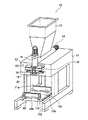
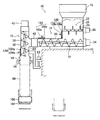
以下、本発明の実施の形態を実施例に基づいて説明する。図1は本発明の包装袋搬出装置を採用した粉体充填装置の1例を示す斜視図、図2は同粉体充填装置の断面図である。図に示すように、この実施例の粉体充填装置10は、粉体貯留部としてのホッパー12に貯留された粉体を、ホッパー12の下方に配置された第1のスクリューコンベア14で水平方向に移送し、この第1のスクリューコンベア14の粉体移送方向における下流側の終端部に配置された第2のスクリューコンベア16で下向きに移送して、第2のスクリューコンベア16の直下に設けられた粉体の充填ノズル18から包装袋20に粉体を供給するものである。
Hereinafter, embodiments of the present invention will be described based on examples. FIG. 1 is a perspective view showing an example of a powder filling apparatus employing the packaging bag carrying out apparatus of the present invention, and FIG. 2 is a cross-sectional view of the powder filling apparatus. As shown in the figure, the
ここで、粉体貯留部としてのホッパー12には、粉体がブリッジを形成して粉体の流下を阻害することのないように、ホッパー12の内部に粉体を攪拌する攪拌装置22を有することが望ましい。この攪拌装置22は、図示するように、回転する軸24の周りに棒状の突起26を設けてモータ28で駆動するものなどが好適に使用することができる。
Here, the
ホッパー12の下方には、粉体貯留部としてのホッパー12から流下して供給される粉体をほぼ水平方向に移送する第1のスクリューコンベア14が設けられている。この実施例の第1のスクリューコンベア14は、粉体を移送するための通常のスクリューコンベアであり、外筒30の内面と僅かな間隙を保って回転するスクリュー32がモータ34によって駆動されて粉体を移送する。
Below the
第2のスクリューコンベア16も同様のスクリューコンベアであり、外筒36の内面と僅かな間隙を保って回転するスクリュー38がモータ40によって駆動されて粉体を移送する。ここで、この実施例では、第1のスクリューコンベア14の粉体移送方向における下流側の終端部に、第2のスクリューコンベア16の回転軸がほぼ鉛直に配置されている。
The
そして、第1のスクリューコンベア14と第2のスクリューコンベア16との間隙に、第1のスクリューコンベア14と第2のスクリューコンベア16とを接続するゴムなどの可撓性の弾性体からなる接続部材42が設けられている。これにより、第1のスクリューコンベア14と第2のスクリューコンベア16とが重量的に縁を切られ、後述するように、計量装置62によって、第2のスクリューコンベア16に入った粉体の重量を正確に計測できるようにされている。この接続部材42は、図2では可撓性であることを明確に示すためにベローズ状に描かれているが、実際には、粉体が内面に滞留することを防止するために、少なくとも内面は平滑なチューブ状となっていることが望ましい。
And the connection member which consists of flexible elastic bodies, such as rubber | gum which connects the
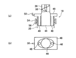
第2のスクリューコンベア16の下側に位置する粉体移送方向における下流側の終端部には、供給する粉体を包装袋20に充填するための充填ノズル18が配置されている。この充填ノズル18は、図3(a)に断面図を、図3(b)に下面図を示すように、第2のスクリューコンベア16の直下に配置されたほぼ楕円形の突起した形状であって、中央に粉体を供給する充填口44が、長軸に沿ったその両側に粉体とともに供給された空気を排出する排気孔46が形成されている。
A filling
この充填ノズル18は、充填口44が第2のスクリューコンベア16の外筒36の内径とほぼ同径かやや大径となる寸法で接続されており、第2のスクリューコンベア16で移送された粉体は、そのまま充填ノズル18の充填口44を通過して包装袋20に充填される。このとき、粉体と同時に空気が移送されてくるので、この空気を包装袋20から排出するために排気孔46が形成されている。この排気孔46は、充填口44の上部に配置された空気室48を経て、パイプ50を通って外部に排出される。このとき、任意の吸引装置を使用することによって、より効率的に排気することができる。
The filling
包装袋20は、充填ノズル18の下方の位置に、包装袋保持装置52によって吊り下げた状態で保持されている。この包装袋保持装置52は、包装袋20の供給装置(図示しない)で充填ノズル18の位置に供給され、上側の開口部を開いて充填ノズル18に被せるように配置された包装袋20を、吊り下げた状態で充填ノズル18に密着するように押し付けて保持するものであって、充填ノズル18の楕円形の突起した形状に対応する形状の2個の包装袋保持アーム54と、この包装袋保持アーム54を開閉する保持アーム駆動機構56とからなっている。そして、包装袋保持アーム54の包装袋20に接する面には、包装袋20を確実に充填ノズル18に密着させるために、ゴムなどの弾性体による押圧部材58を配置しておくことが望ましい。
The
この実施例の保持アーム駆動機構56は、図1に示すように、ロータリーシリンダ60によって包装袋保持アーム54を揺動させるものであって、図2に想像線で示すように、ロータリーシリンダ60が回動することによって包装袋保持アーム54が揺動して、包装袋20を保持し、あるいは開放する。
As shown in FIG. 1, the holding
充填ノズル18の後方(図2では右側)の位置には、包装袋20に充填された粉体の重量を計量する計量装置62が設けられている。この計量装置62は、充填ノズル18に吊り下げた状態で保持されている包装袋20に充填される粉体の重量を、充填中に即時に計測するもので、第2のスクリューコンベア16、充填ノズル18および各種の付属部品も含めた重量を計測し、充填による重量の増加分を計測することで、包装袋20に充填された粉体の重量を計量する。
A measuring
このためにも、第1のスクリューコンベア14と第2のスクリューコンベア16との間隙に設けられたゴムなどの可撓性の弾性体からなる接続部材42が必要となり、この接続部材42によって、第1のスクリューコンベア14が第2のスクリューコンベア16の重量を支えることがないように構成されている。このため、接続部材42は、その剛性によって計測値に誤差が生じないように、充分な可撓性を有することが必要となる。この計量装置62には、従来公知の各種の計量装置を利用することができる。
For this purpose, a connecting
計量装置62は、包装袋20に供給された粉体の重量を測定して、第1のスクリューコンベア14を制御する。具体的には、包装袋20に供給された粉体の重量が包装袋20に充填する所定の重量に近付いたときに、第1のスクリューコンベア14(および必要なときには第2のスクリューコンベア16)のスクリュー32(およびスクリュー38)の回転を減速し、所定の重量に到達したときに、第1のスクリューコンベア14の回転を停止する。このとき、第2のスクリューコンベア16のスクリュー38の回転は継続して、接続部64の粉体をスクリュー38で掻き落とすために所定の短い時間を経過してから停止する。
The weighing
このように制御することによって、第1のスクリューコンベア14と第2のスクリューコンベア16との接続部64に充満している粉体が第2のスクリューコンベア16によって掻き落とされるので、従来技術のように粉体が塊状になって落下することがなくなり、粉体を包装袋20に高い精度で充填することができる。
By controlling in this way, the powder filling the connecting
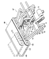
充填ノズル18に吊り下げた状態で保持されている包装袋20の下方には、所定の量の粉体が充填された包装袋20を搬出する搬出装置として、ベルトコンベアなどの搬出コンベア66および搬出コンベア66の上下装置67が配置されている。この搬出コンベア66およびその上下装置67は、粉体が充填された包装袋20を衝撃なく下から受け取って外部に搬出するためのもので、搬出コンベア66を上下および前後(図2では左右動)に移動する機構を有している。この実施例では、粉体充填装置10の支持台11の内部に設置でき、かつ、短時間で所望の経路での上下動および前後動が可能な機構として、図4に示す本発明に係る包装袋搬出コンベアの上下装置67が採用されている。
Below the
図1および図2においては、包装袋搬出装置のうち、搬出コンベア66のみを示し、包装袋搬出コンベアの上下装置67を示していないが、包装袋搬出コンベアの上下装置67は、充填ノズル18の後ろ側(図1および図2における右側)の、粉体充填装置10の支持台11の内部に配置されている。
In FIG. 1 and FIG. 2, only the carry-out
本発明に係る包装袋搬出コンベアの上下装置67は、図4に示すように、図示しない軸受によって回転自在に支持された第1の回転軸68にその一端が固定され、この第1の回転軸68を駆動する第1の駆動モータ70の正逆回転によって揺動する第1のリンク72と、この第1のリンク72の揺動する他端に一端が回動自在に連結され、第1のリンク72の揺動によって上下方向に移動する第2のリンク74と、この第2のリンク74の上下動する他端に回動自在に連結された支持軸76と、この支持軸76に一端が回動自在に連結され、他端が前後動軸78に回動自在に連結された第3のリンク80とによって上下動機構が構成されている。そして、第1の駆動モータ70の正逆回転によって第1のリンク72、第2のリンク74および第3のリンク80が想像線で示すように揺動して搬出コンベア66を上下動させる。
As shown in FIG. 4, the lifting
すなわち、第1の駆動モータ70が正逆回転することによって、第1の回転軸68が往復回転して第1のリンク72が揺動する。そして、第3のリンク80のピボットとなる前後動軸78の位置が固定されているときには、この第1のリンク72の揺動によって、第2のリンク74と第3のリンク80が揺動して支持軸76に固定された搬出コンベア66が上下方向に移動する。
That is, when the
また、図示しない軸受によって回転自在に支持された第2の回転軸82にその一端が固定され、この第2の回転軸82を駆動する第2の駆動モータ84の正逆回転によって揺動する第4のリンク86と、この第4のリンク86の揺動する他端に設けられた前述した前後動軸78と、この前後動軸78に一端が回動自在に連結され、第4のリンク86の揺動によって前後方向に移動する前述した第3のリンク80と、この第3のリンク80の他端に回動自在に連結された前述した支持軸76とによって前後動機構が構成されている。
In addition, one end is fixed to a second
したがって、前後動機構では、第2の駆動モータ84が正逆回転するときには、第2の回転軸82が往復回転して第4のリンク86が揺動し、第3のリンク80を介して支持軸76に固定された搬出コンベア66が前後方向に移動する。
Therefore, in the longitudinal movement mechanism, when the
さらに、第2の回転軸82に回動自在に設けられ、回転不能に係止された第1の伝導手段である歯付きプーリ88と、前後動軸78に固定された第3の伝導手段である歯付きプーリ90、92と、支持軸76に固定された第2の伝導手段である歯付きプーリ94と、歯付きプーリ88と歯付きプーリ90との間に巻回された歯付きベルト96および歯付きプーリ92と歯付きプーリ94との間に巻回された歯付きベルト98とによって回り止め機構が構成されている。
Furthermore, a
この回り止め機構は、プーリ88、90、92、94と歯付きベルト96、98に限定されるものではなく、回り止め機構として有効な任意の機構を採用することができることはもちろんであるが、この回り止め機構を採用することによって、上下動機構および前後動機構にプーリ88、90、92、94および歯付きベルト96、98を追加するのみで回り止め機構とすることができるので、より安価で簡便な回り止め機構とすることができる。
This anti-rotation mechanism is not limited to the
そして、支持軸76には、詳細は後述する包装袋20の搬出コンベア66が固定されている。したがって、この搬出コンベア66は、回り止め機構によって傾斜することが阻止された状態で、上下動機構と前後動機構によって上下方向と前後方向に自由に移動することができる。もちろん、上下動機構あるいは前後動機構を単独で作動させると、それぞれ円弧状の動きをするが、駆動モータ70、84の回転を同期するように制御して駆動することによって、任意の軌跡を通って搬出コンベア66を移動させることができる。
And the carrying-out
ここで、搬出コンベア66の軌跡(移動経路)を、充填部から所定の搬出位置までを結ぶ略円弧状に選択し、搬出コンベア66を上下方向と前後方向とに同時に移動させることにより、上下方向と前後方向とに別々に移動させる場合に比べて、1サイクルの移動時間を大幅に短縮することができ、かつ、充填部に次の包装袋を供給するための、充填ノズル18の下方の空間を素早く開放することができる。例えば、この実施例においては、搬出コンベア66の移動の1サイクルは、7.5秒以内を実現でき、従って、粉体充填装置10の充填サイクルは、7.5秒という高速化を実現できる。
Here, the trajectory (movement path) of the carry-out
そして、この実施例では、これらの上下動機構、前後動機構および回り止め機構によって、本発明の包装袋搬出装置を構成する、包装袋搬出コンベアの上下装置67を構成している。
In this embodiment, the up-and-down
また、包装袋搬出コンベアの上下装置67は、上記の構成により、上下動機構および前後動機構の動作するスペースとほぼ同等のスペースに収めることができ、コンパクトな装置とすることができるので、従来の装置のように、搬出装置が装置本体から大幅にはみ出すこともなく、装置本体とは別のスペースを用意する必要もなく、支持台11の内部に配置することができ、粉体充填装置10の占有床面積が小さくて済む、すなわち、省スペース化を実現できるという利点を有している。
Moreover, the
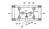
図4に示すように、粉体が充填された包装袋20を搬出する搬出コンベア66が、支持軸76に固定して設けられている。この搬出コンベア66は、支持軸76に平行に包装袋20を搬出するベルトコンベアであって、図5に平面断面図として示すように、2個のフレーム100に回転自在に保持されたコンベアプーリ102によってコンベアベルト104が張架されている。そして、この搬出コンベア66は、図示しないモータによって駆動され、コンベアベルト104が図4に矢印で示す方向に移動して、粉体が充填された包装袋20を外部に搬出する。
As shown in FIG. 4, an unloading
コンベアベルト104の両側面には、図1、図2および図5に示すように、粉体の充填された包装袋20を保持する保持板106が設けられている。この保持板106は、搬出コンベア66の上面に載置された包装袋20が倒れることを防止するために両側面から保持するものであって、包装袋搬出コンベアの上下装置67によって、搬出コンベア66とともに上下方向および前後方向に移動する。この実施例では、保持板106は、開閉自在とされており、保持板駆動手段108によって開閉するように駆動される。
As shown in FIGS. 1, 2, and 5, holding
保持板駆動手段108は、この実施例では、油圧または空圧のシリンダ110によってリンク列112が移動し、このリンク列112の終端に固定された保持軸114を移動して、この保持軸114に固定された保持板106を開閉するものである。このリンク列112は、図5に示すように、シリンダ110のピストン116の出没によって移動するもので、単純な通常のリンク列を構成している。
In this embodiment, the holding plate driving means 108 moves the holding
搬出コンベア66および包装袋搬出コンベアの上下装置67は、このように構成されているので、包装袋20への粉体の充填時、すなわち充填量の計量時には、包装袋20に触れることなく包装袋20の下方で待機し、充填が完了すると、包装袋搬出コンベアの上下装置67によって、図2に、上側の想像線で描かれたように、搬出コンベア66が包装袋20を支持する上昇位置まで上昇する。そして、保持板106が閉じ、保持板106で包装袋20を保持して下降するとともに、図中右側の想像線で描かれた搬出位置、すなわち、充填ノズル18の後ろ側に移動する。ここで、上述したように、包装袋20は、充填ノズル18に被せて配置されているので、搬出コンベア66の移動経路は、包装袋20が充填ノズル18に極力接することなく、無理なく外れるように設定される。
Since the carry-out
このとき、駆動モータ70、84の回転速度を適宜制御して搬送コンベア66の上下および前後方向の移動速度を制御することによって、包装袋20を衝撃なく受け取って移動することができるので、包装袋20の開口部がシールされていなくても、粉体がこぼれる等の問題は生じない。また、搬出コンベア66を振動させる手段を設け、充填完了後の包装袋20を搬出コンベア66で支持した後に、搬出コンベア66を適宜振動させることにより包装袋20の中の粉体を詰まった状態にして、搬送安定性を向上させるのも好ましい。もちろん、粉体を充填する作業に包装袋をシールする時間の余裕があるときには、包装袋保持アーム54を開放して搬出コンベア66が下降した時点で、任意のシール手段によって包装袋20の開口部をシールするのも、運搬の容易性をより高くし、異物混入の可能性をさらに低くできる点で好ましい。
At this time, the
搬出位置まで搬出コンベア66で移動した粉体の充填された包装袋20は、搬出コンベア66のコンベアプーリ102が回転してコンベアベルト104が図4の矢印方向に移動することにより、搬出コンベア66から搬出され、搬出コンベア66に続く任意の搬送手段、例えば、搬出コンベア66と同じ方向または直交する方向に移動するベルトコンベアなどで搬送され、開口部のシール、検品等の工程を経て出荷され、あるいは倉庫に収納される。なお、本実施例では、包装袋20の搬出位置は、支持台11(図1参照)の側面中央部に設けられた搬出口11aに対応する位置とされており、この搬出位置へ移動された包装袋20は、搬出口11aから粉体充填装置10の外部へ搬出される。
The
搬出コンベア66から包装袋20が搬出されると、搬出コンベア66は、包装袋搬出コンベアの上下装置67によって、速やかに初期位置(包装袋の待機位置)に戻り、次の包装袋の充填完了を待機し、以下同様の動作を繰り返す。
When the
また、搬出コンベア66および包装袋搬出コンベアの上下装置67が、包装袋20を充填部から移動させるとすぐに、例えば、充填ノズル18の前側(図2における左側)に配置された、図示しない包装袋の供給手段によって、次の包装袋が充填ノズル18の位置に供給されて、次の充填が行われる。ここで、搬出コンベア66および包装袋搬出コンベアの上下装置67による包装袋20の移動は、上述したように、下降するとともに図2中右側へ行われるので、包装袋20の移動量が小さくても、すなわち、搬出位置へ完全に搬出される前であっても、充填部およびその下方が開放される。そのため、次の包装袋を早いタイミングで充填ノズル18に供給することができ、粉体充填装置10の充填包装効率を向上させることができる。
Further, as soon as the carry-out
なお、上述の実施例では、包装袋搬出装置として、搬出コンベア66を備えるものとし、搬出コンベア66によって包装袋20を外部へ搬出しているが、本発明はこれには限定されない。例えば、搬出コンベア66に代えて包装袋20の載置台を備え、包装袋搬出装置からの包装袋20の搬出部に、載置台から外部の搬送手段へ包装袋20を押し出す、または、引っ張る手段等を備えてもよいし、載置台上の包装袋20を保持して外部へ搬出する手段を備える形態としてもよい。
In the above-described embodiment, the packaging bag unloading device includes the unloading
また、この実施例では、包装袋搬出コンベアの上下装置67が、粉体充填装置10の前後方向に搬出コンベア66を移動するように配置されているが、これには限定されず、包装袋の供給手段や、外部のベルトコンベア等の搬送手段の配置に応じて、左右方向等、水平平面内の1方向に移動するように配置されればよい。
Further, in this embodiment, the
なお、この粉体充填装置10では、粉体に混入して共に移送される空気を排出するために脱気口を設けることが望ましい。この脱気口としては、粉体貯留部の攪拌装置22の近傍に設ける脱気口120、第1のスクリューコンベア14の粉体移送方向における下流側の終端部の近傍に設ける脱気口122、第2のスクリューコンベア16の粉体移送方向における充填ノズル18の近傍に設ける脱気口124などがあり、この脱気口120、122、124の少なくとも1箇所に脱気口を設けることが望ましい。脱気口120,122,124は、粉体充填装置10の各部の壁等に配されたフィルタ120a,122a,124aと、これらのフィルタを通して排気された空気を回収する脱気管120b,122b,124b等から構成され、脱気管120b,122b,124bには、図示しない吸気装置が接続されればよい。
In the
本発明の包装袋搬出装置は、以上に説明したように構成されているので、例えば、移送速度を制限する充填ノズルのラッパ状に細くなった部分がなく、第2のスクリューコンベアの下側の開放部に粉体の充填ノズルが形成されている構成であって、高速で粉体を送っても粉体が詰まることがなく、短時間で粉体を包装袋に充填することができ、かつ、包装袋を吊り下げた状態で充填しながらその充填量を計量する粉体充填装置に採用した場合にも、充填中は包装袋に接することなく、充填後に、粉体が高速で充填された包装袋を受け取って短時間で搬出することができ、また、次の包装袋を素早く供給することができるので、粉体充填装置の充填包装効率の向上を実現することができる。 Since the packaging bag carry-out device of the present invention is configured as described above, for example, there is no portion of the filling nozzle that is narrowed in a trumpet shape that limits the transfer speed, and the lower side of the second screw conveyor. It is a configuration in which a powder filling nozzle is formed in the open part, and even if the powder is sent at high speed, the powder is not clogged, and the powder can be filled in the packaging bag in a short time, and Even when it is used in a powder filling device that measures the filling amount while filling the packaging bag in a suspended state, the powder is filled at high speed after filling without touching the packaging bag during filling. Since the packaging bag can be received and carried out in a short time, and the next packaging bag can be supplied quickly, the filling and packaging efficiency of the powder filling device can be improved.
したがって、本発明の包装袋搬出装置および包装袋載置台の上下装置は、粉体を包装袋に高速で充填することが可能であり、かつ、包装袋に供給される粉体の量を高い精度で制御することのできる粉体充填装置に対応する包装袋搬出装置を提供することができる。 Therefore, the packaging bag unloading device and the packaging bag mounting table lifting / lowering device of the present invention can fill the packaging bag with powder at a high speed, and the amount of powder supplied to the packaging bag can be highly accurate. The packaging bag carrying-out apparatus corresponding to the powder filling apparatus which can be controlled by can be provided.
なお、上記の実施例では、粉体を充填する粉体充填装置10について説明したが、本発明はこれには限定されず、粉体以外にも、粒体や、固形物等の充填装置であって、包装袋を充填ノズルの下方に吊り下げて充填しながら充填量を計量する形態の充填装置に、好適に利用可能である。
In the above embodiment, the
10 粉体充填装置
11 支持台
12 ホッパー
14 第1のスクリューコンベア
16 第2のスクリューコンベア
18 充填ノズル
20 包装袋
22 攪拌装置
24 軸
26 棒状の突起
28 モータ
30,36 外筒
32,38 スクリュー
34,40 モータ
42 接続部材
44 充填口
46 排気孔
48 空気室
50 パイプ
52 包装袋保持装置
54 包装袋保持アーム
56 保持アーム駆動機構
58 押圧部材
60 ロータリーシリンダ
62 計量装置
64 接続部
66 搬出コンベア
67 包装袋搬出コンベアの上下装置
68 第1の回転軸
70 第1の駆動モータ
72 第1のリンク
74 第2のリンク
76 支持軸
78 前後動軸
80 第3のリンク
82 第2の回転軸
84 第2の駆動モータ
86 第4のリンク
88,90,92,94 歯付きプーリ
96,98 歯付きベルト
100 フレーム
102 コンベアプーリ
104 コンベアベルト
106 保持板
108 保持板駆動手段
110 シリンダ
112 リンク列
114 保持軸
116 ピストン
120,122,124 脱気口
DESCRIPTION OF
Claims (10)
一端が第2の回転軸に固定され、この第2の回転軸を駆動する第2の駆動モータの正逆回転によって揺動する第4のリンクと、この第4のリンクの揺動する他端に回動自在に設けられた前記前後動軸と、この前後動軸に一端が回動自在に連結され、第4のリンクの揺動によって前後方向に移動する前記第3のリンクと、この第3のリンクの他端に回動自在に連結された前記支持軸とからなる前後動機構と、
前記第2の回転軸に回動自在に設けられ、回転不能に係止された第1の伝導手段と、前記支持軸に固定された第2の伝導手段とからなり、前記支持軸を回転不能に係止する回り止め機構とからなることを特徴とする粉体充填装置の粉体充填部における包装袋載置台の上下装置。 A first link, one end of which is fixed to the first rotating shaft and rocks by forward and reverse rotation of a first drive motor that drives the first rotating shaft, and the other end of the first link that rocks One end of the second link is pivotally connected to the second link, and the second link is moved up and down by the swing of the first link, and the other end of the second link is pivotally connected to the other end of the second link. A vertical movement mechanism comprising a shaft and a third link having one end rotatably connected to the support shaft and the other end rotatably connected to the longitudinal movement shaft;
A fourth link, one end of which is fixed to the second rotating shaft and swings by forward and reverse rotation of a second drive motor that drives the second rotating shaft, and the other end swinging of the fourth link The forward / backward movement shaft provided on the front / rear movement shaft, the third link having one end rotatably connected to the front / rear movement shaft, and moving in the front / rear direction by the swing of the fourth link; A back-and-forth movement mechanism comprising the support shaft rotatably connected to the other end of the link of 3;
The first rotation means is provided on the second rotation shaft so as to be rotatable and is locked so as not to rotate. The second conduction means is fixed to the support shaft, and the support shaft cannot be rotated. And an anti-rotation mechanism for locking to the packaging bag mounting table in the powder filling unit of the powder filling device.
前記包装袋の載置台と、
前記載置台を、前記充填位置において前記包装袋の底部を支持する第1の位置、および、前記第1の位置から下方向に離間した第2の位置の間で移動する上下動機構と、
前記載置台を、前記第2の位置、および、前記第2の位置の後方へ水平方向に離間した、前記包装袋を搬出する第3の位置の間で移動する前後動機構と、
前記載置台の載置面を水平に維持する水平維持機構と、を有し、
前記上下動機構と前記前後動機構とを同時に駆動することにより、前記載置台を、前記第2の位置を通過させずに、前記第1の位置および前記第3の位置の間で移動させることを特徴とする包装袋搬出装置。 A filling nozzle, a packaging bag holding device that suspends and holds a packaging bag below the filling nozzle, and a filling material filled from the filling nozzle into the packaging bag that is suspended and held by the packaging bag holding device. A packaging bag unloading device for moving the packaging bag from a filling position by the filling nozzle to an unloading position to the outside.
A mounting table for the packaging bag;
A vertical movement mechanism that moves the mounting table between a first position that supports a bottom portion of the packaging bag at the filling position and a second position that is spaced downward from the first position;
A back-and-forth movement mechanism that moves the mounting table between the second position and a third position that is horizontally spaced rearward of the second position and that unloads the packaging bag;
A horizontal maintaining mechanism for maintaining the mounting surface of the mounting table horizontally;
By simultaneously driving the vertical movement mechanism and the longitudinal movement mechanism, the mounting table is moved between the first position and the third position without passing through the second position. A packaging bag unloading device.
前記前後動機構は、一端が第2の回転軸に固定され、この第2の回転軸を駆動する第2の駆動モータの正逆回転によって揺動する第4のリンクと、この第4のリンクの揺動する他端に回動自在に設けられた前記前後動軸と、この前後動軸に一端が回動自在に連結され、第4のリンクの揺動によって前後方向に移動する前記第3のリンクと、この第3のリンクの他端に回動自在に連結された前記支持軸とからなり、
前記載置台は、その一縁部が前記支持軸に固定されており、
前記水平維持機構は、前記第2の回転軸に回動自在に設けられ、回転不能に係止された第1の伝導手段と、前記支持軸に固定された第2の伝導手段とからなる、前記支持軸を回転不能に係止する回り止め機構であることを特徴とする請求項6に記載の包装袋搬出装置。 One end of the vertical movement mechanism is fixed to the first rotation shaft, and the first link swings by forward and reverse rotation of a first drive motor that drives the first rotation shaft, and the first link. One end of the second link is pivotally connected to the other swinging end of the first link, and the second link moves up and down by the swinging of the first link, and the other end of the second link moves up and down. A support shaft that is freely connected, and a third link having one end rotatably connected to the support shaft and the other end rotatably connected to the longitudinal axis.
The forward / backward movement mechanism has one end fixed to the second rotation shaft, and a fourth link that swings by forward and reverse rotation of a second drive motor that drives the second rotation shaft, and the fourth link. The forward / backward movement shaft rotatably provided at the other swinging end, and the third forward / backward movement shaft is connected to the forward / backward movement shaft in a freely rotatable manner, and the third link moves in the front / rear direction by swinging the fourth link. And the support shaft rotatably connected to the other end of the third link,
The mounting table has one edge fixed to the support shaft,
The horizontal maintaining mechanism includes a first conduction means that is rotatably provided on the second rotation shaft and is non-rotatably locked, and a second conduction means that is fixed to the support shaft. The packaging bag unloading device according to claim 6, wherein the packaging bag unloading device is a non-rotating mechanism for locking the support shaft so as not to rotate.
前記計量装置による計量時には、前記載置台を、前記包装袋保持装置によって吊り下げて保持された前記包装袋よりも下方に配置し、
前記計量の後に、前記第1の位置に前記載置台を移動させて前記包装袋の底部を支持し、
前記包装袋保持装置による前記包装袋の保持が解放された後に、前記第1の位置から前記第3の位置に、前記第2の位置を通過させずに、前記載置台を移動させて前記包装袋を搬出することを特徴とする請求項6または7に記載の包装袋搬出装置。 The vertical movement mechanism and the longitudinal movement mechanism are:
At the time of weighing by the weighing device, the mounting table is disposed below the packaging bag suspended and held by the packaging bag holding device,
After the weighing, move the mounting table to the first position to support the bottom of the packaging bag,
After the holding of the packaging bag by the packaging bag holding device is released, the packaging table is moved from the first position to the third position without passing the second position, and the packaging is moved. The packaging bag carrying-out device according to claim 6 or 7, wherein the bag is carried out.
Priority Applications (1)
| Application Number | Priority Date | Filing Date | Title |
|---|---|---|---|
| JP2004112853A JP2005297976A (en) | 2004-04-07 | 2004-04-07 | Device for vertically moving packaging bag loading table, and packaging bag carrying-out device |
Applications Claiming Priority (1)
| Application Number | Priority Date | Filing Date | Title |
|---|---|---|---|
| JP2004112853A JP2005297976A (en) | 2004-04-07 | 2004-04-07 | Device for vertically moving packaging bag loading table, and packaging bag carrying-out device |
Publications (1)
| Publication Number | Publication Date |
|---|---|
| JP2005297976A true JP2005297976A (en) | 2005-10-27 |
Family
ID=35330003
Family Applications (1)
| Application Number | Title | Priority Date | Filing Date |
|---|---|---|---|
| JP2004112853A Withdrawn JP2005297976A (en) | 2004-04-07 | 2004-04-07 | Device for vertically moving packaging bag loading table, and packaging bag carrying-out device |
Country Status (1)
| Country | Link |
|---|---|
| JP (1) | JP2005297976A (en) |
Cited By (5)
| Publication number | Priority date | Publication date | Assignee | Title |
|---|---|---|---|---|
| CN102295089A (en) * | 2011-05-27 | 2011-12-28 | 楚天科技股份有限公司 | Bottle conveying mechanism used for freeze-drying line |
| CN109533473A (en) * | 2018-12-24 | 2019-03-29 | 贵州大学 | A kind of capsule class product automation weigher |
| CN112141380A (en) * | 2020-10-01 | 2020-12-29 | 安徽省泗县瑞丰面粉有限公司 | Flour shaping is mixing device for packing |
| CN116588382A (en) * | 2023-06-13 | 2023-08-15 | 安徽森淼实业有限公司 | Hydroxypropyl methylcellulose powder environment-friendly packaging device |
| CN117508797A (en) * | 2023-12-25 | 2024-02-06 | 无锡市兴百利机械设备有限公司 | Bulk material packaging equipment |
-
2004
- 2004-04-07 JP JP2004112853A patent/JP2005297976A/en not_active Withdrawn
Cited By (8)
| Publication number | Priority date | Publication date | Assignee | Title |
|---|---|---|---|---|
| CN102295089A (en) * | 2011-05-27 | 2011-12-28 | 楚天科技股份有限公司 | Bottle conveying mechanism used for freeze-drying line |
| CN109533473A (en) * | 2018-12-24 | 2019-03-29 | 贵州大学 | A kind of capsule class product automation weigher |
| CN112141380A (en) * | 2020-10-01 | 2020-12-29 | 安徽省泗县瑞丰面粉有限公司 | Flour shaping is mixing device for packing |
| CN112141380B (en) * | 2020-10-01 | 2022-02-01 | 安徽省泗县瑞丰面粉有限公司 | Flour shaping is mixing device for packing |
| CN116588382A (en) * | 2023-06-13 | 2023-08-15 | 安徽森淼实业有限公司 | Hydroxypropyl methylcellulose powder environment-friendly packaging device |
| CN116588382B (en) * | 2023-06-13 | 2023-11-21 | 安徽森淼实业有限公司 | Hydroxypropyl methylcellulose powder environment-friendly packaging device |
| WO2024255169A1 (en) * | 2023-06-13 | 2024-12-19 | 安徽森淼实业有限公司 | Environmentally friendly packaging device for hydroxypropyl methylcellulose powder |
| CN117508797A (en) * | 2023-12-25 | 2024-02-06 | 无锡市兴百利机械设备有限公司 | Bulk material packaging equipment |
Similar Documents
| Publication | Publication Date | Title |
|---|---|---|
| CN100439205C (en) | Apparatus and method for filling foil-lined pouches with food | |
| CN101223423B (en) | Metering device | |
| JP4409429B2 (en) | Capsule filling and sealing device | |
| JP6983715B2 (en) | Bagging and packaging machine and bagging and packaging method | |
| JP4402967B2 (en) | Powder filling equipment | |
| JP2005008282A (en) | Feeder of powder | |
| CN110874889B (en) | Automatic packaging vending machine for loose rice | |
| JP2005297976A (en) | Device for vertically moving packaging bag loading table, and packaging bag carrying-out device | |
| JP4785610B2 (en) | Powder filling and packaging method and powder filling and packaging system | |
| JPH08504597A (en) | Device for agitating tobacco filters in the filter hopper | |
| JP2004314983A (en) | Bagging apparatus for dry ingredients | |
| JP2003237701A (en) | Quantitative feeding apparatus and packaging machine for powder | |
| JP4427432B2 (en) | Powder filling method | |
| JPH10250843A (en) | Powder replenishment method and device of powder supply machine and powder supply machine | |
| JP2005035736A (en) | Conveyance mechanism and quantitative filling machine | |
| CN113697197B (en) | Conveying system for axial plunger pump | |
| JP4275779B2 (en) | Filling and packing machine for powder and granule with a small amount of addition equipment | |
| JP2003237886A (en) | Granular dry ice distribution and supply device, and continuous supply system for granular dry ice | |
| CN211365231U (en) | Receiving device and equipment for packing | |
| US4982873A (en) | Two-stage auger system for filling commercial valve bags | |
| JP2013018558A (en) | Feeding device for material to be weighed | |
| JP4207533B2 (en) | Powder filling equipment | |
| JP2005015129A (en) | Feeder for powder | |
| JP2006296363A (en) | Weighing seasoning apparatus and confectionery manufacturing system using the same | |
| JP2581584Y2 (en) | Quantitative bagging equipment for granular materials |
Legal Events
| Date | Code | Title | Description |
|---|---|---|---|
| A300 | Withdrawal of application because of no request for examination |
Free format text: JAPANESE INTERMEDIATE CODE: A300 Effective date: 20070703 |