JP2005297966A - Leather-wound steering wheel - Google Patents
Leather-wound steering wheel Download PDFInfo
- Publication number
- JP2005297966A JP2005297966A JP2005203165A JP2005203165A JP2005297966A JP 2005297966 A JP2005297966 A JP 2005297966A JP 2005203165 A JP2005203165 A JP 2005203165A JP 2005203165 A JP2005203165 A JP 2005203165A JP 2005297966 A JP2005297966 A JP 2005297966A
- Authority
- JP
- Japan
- Prior art keywords
- leather
- synthetic resin
- soft synthetic
- hard
- terminal
- Prior art date
- Legal status (The legal status is an assumption and is not a legal conclusion. Google has not performed a legal analysis and makes no representation as to the accuracy of the status listed.)
- Granted
Links
Images
Landscapes
- Steering Controls (AREA)
Abstract
Description
本発明は、車両の操舵用のステアリングホイールに関し、特に、操舵時に把持する円環状のリング部の芯金周囲に、リング部の形成方向に沿うように、硬質部と軟質合成樹脂部とが配置されて、軟質合成樹脂部の周囲に皮革が配置されて構成される革巻きステアリングホイールに関する。 The present invention relates to a steering wheel for steering a vehicle, and in particular, a hard portion and a soft synthetic resin portion are arranged around a cored bar of an annular ring portion that is gripped during steering so as to follow the direction in which the ring portion is formed. The present invention also relates to a leather-wrapped steering wheel configured by arranging leather around a soft synthetic resin portion.
従来、革巻きステアリングホイールでは、リング部の芯金の周囲に、発泡ウレタン等からなる軟質合成樹脂部を設けて、その周囲に皮革を縫合して配置させていた。 Conventionally, in a leather-wrapped steering wheel, a soft synthetic resin portion made of urethane foam or the like is provided around a core metal of a ring portion, and leather is sutured around the periphery.
そのため、意匠上の要請から、リング部の芯金周囲に、リング部の形成方向に沿うように、硬質部と、硬質部より軟質の軟質合成樹脂部と、を配置させて、その軟質合成樹脂部の周囲に皮革を配置させるような場合、皮革の硬質部側の端末が、軟質合成樹脂部の弾性で凹む態様となって、その皮革の端末に、アールダレ(シャープな角とならずに角が大きなアールで丸くなること)が生じ、皮革端末の外観意匠を低減させることとなっていた。 Therefore, according to the design requirement, a hard synthetic resin portion that is softer than the hard portion and a soft synthetic resin portion that is softer than the hard portion is arranged around the core metal of the ring portion so as to follow the forming direction of the ring portion. When leather is placed around the part, the end on the hard part side of the leather becomes a concave shape due to the elasticity of the soft synthetic resin part. Is rounded with a large radius), and the appearance design of the leather terminal has been reduced.
本発明は、上述の課題を解決するものであり、リング部の芯金周囲に、リング部の形成方向に沿うように、硬質部と、硬質部より軟質の軟質合成樹脂部と、が配置されて、軟質合成樹脂部の周囲に皮革が配置されることとなっても、皮革の端末にアールダレが生じず、皮革の端末の外観を良好にできる革巻きステアリングホイールを提供することを目的とする。 The present invention solves the above-mentioned problem, and a hard part and a soft synthetic resin part softer than the hard part are arranged around the core metal of the ring part so as to follow the forming direction of the ring part. In addition, even if leather is arranged around the soft synthetic resin portion, an object of the present invention is to provide a leather-wrapped steering wheel capable of improving the appearance of a leather terminal without causing an arthrare in the leather terminal. .
本発明に係るステアリングホイールは、操舵時に把持する円環状のリング部の芯金周囲に、リング部の形成方向に沿うように、硬質部と該硬質部より軟質の軟質合成樹脂部とが配置されて、
該軟質合成樹脂部の周囲に皮革が配置されて構成される革巻きステアリングホイールであって、
前記硬質部における前記軟質合成樹脂部側の端部に、前記皮革の端末を嵌合させる環状溝と、該環状溝の前記軟質合成樹脂部側に配置されて、前記皮革の端末付近を直接支持可能な円柱状の支持部と、が形成され、
前記皮革が、端末付近を前記支持部の外周面に直接当接させつつ、端末を前記環状溝に嵌合させて、配置されていることを特徴とする。
In the steering wheel according to the present invention, a hard portion and a soft synthetic resin portion that is softer than the hard portion are arranged around the core metal of an annular ring portion that is gripped at the time of steering so as to follow the forming direction of the ring portion. And
A leather-wrapped steering wheel configured by arranging leather around the soft synthetic resin part,
An annular groove for fitting the end of the leather to the end of the hard portion on the side of the soft synthetic resin portion, and an arrangement of the annular groove on the side of the soft synthetic resin portion to directly support the vicinity of the end of the leather A cylindrical support capable of being formed,
The leather is arranged by fitting the terminal into the annular groove while bringing the vicinity of the terminal into direct contact with the outer peripheral surface of the support portion.
また、前記芯金における前記軟質合成樹脂部の配置部位で、かつ、前記硬質部の近傍部位には、突起を設けることが望ましい。 In addition, it is desirable that a protrusion be provided in a portion where the soft synthetic resin portion is disposed in the metal core and in the vicinity of the hard portion.
さらに、前記硬質部における前記支持部の前記軟質合成樹脂部側の端末外周には、環状凹部を設けることが望ましい。 Furthermore, it is desirable to provide an annular recess on the outer periphery of the terminal on the soft synthetic resin portion side of the support portion in the hard portion.
本発明に係る革巻きステアリングホイールでは、皮革が、端末付近を硬質部における支持部の外周面に直接当接させつつ、端末を硬質部に設けられた環状溝に嵌合させて、配置されており、皮革の端末を、軟質合成樹脂部でなく、硬質部に設けられた支持部の角部で曲げるように配置できることから、皮革端末にアールダレが生じず、皮革端末の外観を良好にすることができる。 In the leather-wrapped steering wheel according to the present invention, the leather is arranged by fitting the terminal into an annular groove provided in the hard part while bringing the vicinity of the terminal into direct contact with the outer peripheral surface of the support part in the hard part. Since the leather terminal can be arranged to bend at the corners of the support part provided in the hard part instead of the soft synthetic resin part, the leather terminal does not generate an sag and the appearance of the leather terminal is improved Can do.
また、皮革端末を直接支持する硬質部の支持部は、軟質合成樹脂部を成形する際の、バリ切りの役目を果すことができ、軟質合成樹脂部の成形材料が環状溝に入り込むことを防止することができる。 In addition, the support part of the hard part that directly supports the leather terminal can play the role of deburring when molding the soft synthetic resin part, preventing the molding material of the soft synthetic resin part from entering the annular groove can do.
したがって、本発明の革巻きステアリングホイールでは、リング部の芯金周囲に、リング部の形成方向に沿うように、硬質部と、硬質部より軟質の軟質合成樹脂部と、が配置されて、軟質合成樹脂部の周囲に皮革が配置されることとなっても、皮革の端末にアールダレが生じず、皮革の端末の外観を良好にでき、また、硬質部の支持部によって、軟質合成樹脂部を成形する際のバリ切りが良好となり、軟質合成樹脂部の成形後の後処理を容易にすることができる。 Therefore, in the leather-wrapped steering wheel of the present invention, the hard portion and the soft synthetic resin portion softer than the hard portion are arranged around the core metal of the ring portion so as to follow the direction in which the ring portion is formed. Even if leather is arranged around the synthetic resin part, the leather terminal does not generate an sag, the appearance of the leather terminal can be improved, and the soft synthetic resin part can be formed by the support part of the hard part. Deburring at the time of molding becomes good, and post-processing after molding of the soft synthetic resin portion can be facilitated.
そして、リング部の芯金における軟質合成樹脂部の配置部位で、かつ、硬質部の近傍部位に、突起が設けられている場合には、軟質合成樹脂部の硬質部側が、硬質部から離れるように芯金周囲で剥離しようとしても、突起が抵抗となって、その剥離を防止することが可能となる。 When the soft synthetic resin portion is disposed on the core of the ring portion and a protrusion is provided in the vicinity of the hard portion, the hard portion side of the soft synthetic resin portion is separated from the hard portion. Even if it is going to peel off around the metal core, the protrusion becomes a resistance, and the peeling can be prevented.
さらに、硬質部における支持部の軟質合成樹脂部側の端末外周に、環状凹部が設けられている場合には、その環状凹部内に軟質合成樹脂部が入ることとなる。そのため、皮革の硬質部側の端末側が、芯金周囲に軟質合成樹脂部だけを介在させた状態から、直ちに、硬質部の支持部に支持される状態でなく、硬質部の環状溝に接近するにしたがって、厚さの薄くなった環状凹部内の軟質合成樹脂部で支持された状態を経た後に、支持部に支持される態様となることから、皮革の感触の違和感を低減させることができる。 Furthermore, when the annular recessed part is provided in the terminal outer periphery by the side of the soft synthetic resin part of the support part in a hard part, a soft synthetic resin part will enter in the annular recessed part. Therefore, from the state where only the soft synthetic resin part is interposed around the core metal, the terminal side of the hard part side of the leather immediately approaches the annular groove of the hard part instead of being supported by the support part of the hard part. Therefore, after passing through the state of being supported by the soft synthetic resin portion in the annular recess having a reduced thickness, it becomes a mode of being supported by the support portion, so that the uncomfortable feeling of leather feel can be reduced.
以下、本発明の一実施形態を図面に基づいて説明する。 Hereinafter, an embodiment of the present invention will be described with reference to the drawings.
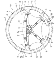
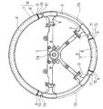
実施形態のステアリングホイールWは、図1に示すように、操舵時に把持する円環状のリング部Rと、リング部Rの中央に配置されるボス部Bと、リング部Rとボス部Bとを連結する4本のスポーク部Sと、を備えて構成され、各部には、相互を連結するためのステアリングホイール芯金1が配設されている。芯金1は、ボス部Bに配置されるボス部芯金2、各スポーク部Sに配置されるスポーク部芯金3、リング部Rに配置されるリング部芯金4、から構成されるとともに、図示しない車両のステアリングシャフトと接続されるボス部芯金2の中央のボス孔2aの周縁の部位を鋼製とするとともに、リング部芯金4を鋼管製として、他の部位を、ダイカスト鋳造によるアルミニウム合金等の軽合金製としている。
As shown in FIG. 1, the steering wheel W of the embodiment includes an annular ring portion R that is gripped at the time of steering, a boss portion B that is disposed at the center of the ring portion R, and a ring portion R and a boss portion B. The four spoke portions S to be connected are provided, and a steering wheel core 1 for connecting each other is disposed in each portion. The core metal 1 is composed of a
そして、リング部Rには、図1〜3に示すように、芯金4の周囲に、リング部Rの形成方向に沿うように、硬質部6と、硬質部6より軟質の軟質合成樹脂部13と、が配置されて、軟質合成樹脂部13の周囲に皮革15が縫合されて配置されている。
As shown in FIGS. 1 to 3, the ring portion R includes a
硬質部6は、実施形態の場合、ステアリングホイールWの前後の部位に合計2つ配置され、それぞれ、発泡エポキシ樹脂等の硬質合成樹脂からなってリング部芯金4の周囲を被覆する本体7と、本体7の周囲を覆う木目調の意匠を表面に表した外皮材8と、から構成されている。
In the case of the embodiment, a total of two
軟質合成樹脂部13は、ステアリングホイールWの左右の部位に配置されて、それぞれ、発泡ウレタン等から形成されている。
The soft
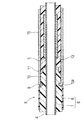
そして、2つの硬質部6・6の本体7における軟質合成樹脂部13側の端部には、それぞれ、皮革15の端末15aを嵌合させる環状溝9と、環状溝9の軟質合成樹脂部13側に配置されて、皮革15の端末15a付近を直接支持可能な円柱状の支持部10と、が形成されている。
Then, at the end of the main body 7 of the two
皮革15は、それぞれ、端末15a付近を支持部10の外周面に直接当接させつつ、端末15aを環状溝9に嵌合させて、配置されている。なお、皮革15・15は、それぞれ、リング部Rにおけるボス部B側の内側で縫合されている。
The
また、リング部芯金4における軟質合成樹脂部13の配置部位で、かつ、硬質部6の近傍部位には、突起5が設けられている。実施形態の場合、突起5は、ダイカスト鋳造されるスポーク部芯金3が鋼管からなるリング部芯金4を連結するように鋳ぐるんだ部位で構成されている。
In addition, a
さらに、2つの硬質部6・6の本体7における支持部10の軟質合成樹脂部13側の端末外周には、その部位の肉厚を支持部10の肉厚の半分程度とするように、環状凹部11が設けられている。
Further, the outer periphery of the end of the
実施形態のステアリングホイールWの製造について説明すると、予め、ステアリングホイール芯金1を製造しておく。ステアリングホイール芯金1の製造は、所定のダイカスト鋳造型に、ボス孔2aの周囲の鋼製の部位と鋼管からなるリング部芯金4とをセットして、ダイカスト鋳造して製造する。
When manufacturing the steering wheel W of the embodiment is described, the steering wheel core 1 is manufactured in advance. The steering wheel mandrel 1 is produced by setting a steel part around the
そして、硬質部本体7・7の成形型に、ステアリングホイール芯金1と外皮材8とをセットし、型締め後、本体7の成形材料を注入して、環状溝9・支持部10・環状凹部11を備えた本体7を成形する。なお、本体7の成形後の状態は、図3の実線で示す状態となる。
Then, the steering wheel core 1 and the
ついで、本体7の成形型から離型させて、軟質合成樹脂部13の成形型に、硬質部6・6を設けたステアリングホイール芯金1をセットし、型締め後、軟質合成樹脂部13の成形材料を注入し、軟質合成樹脂部13を成形する。なお、軟質合成樹脂部13の成形型の型面は、型締め時、本体7の支持部10の外周面を圧接する状態にする。
Next, the steering wheel metal core 1 provided with the
その後、軟質合成樹脂部13の成形型から離型させて、軟質合成樹脂部13・13の周囲に皮革15を縫合して配置させる。その際、皮革15の端末15a付近を硬質部本体7における支持部10の外周面に直接当接させつつ、端末15aを硬質部本体7に設けられた環状溝9に嵌合させて配置させる。なお、支持部10の外周面には、所望により接着剤を塗布して皮革15を接着させても良い。
Thereafter, the soft
さらに、ボス部Bの下部や上部に、図示しないロアカバーやパッドPを取り付ければ、ステアリングホイールWの製造が完了し、車両に装着して使用することができる。なお、車両への装着時には、ステアリングホイールWをステアリングシャフトにナット止めすることから、パッドPを取り外した状態で車両に装着し、装着後にパッドPを組み付けることとなる。 Further, if a lower cover or a pad P (not shown) is attached to the lower part or the upper part of the boss part B, the manufacture of the steering wheel W is completed, and it can be used by being mounted on the vehicle. Since the steering wheel W is nut-fastened to the steering shaft when mounted on the vehicle, the pad P is mounted on the vehicle with the pad P removed, and the pad P is assembled after mounting.
このような実施形態のステアリングホイールWでは、皮革15の端末15aを、軟質合成樹脂部13でなく、硬質部本体7に設けられた支持部10の角部で曲げるように配置できることから、皮革端末15aにアールダレが生じず、皮革端末15aの外観を良好にすることができる。
In the steering wheel W of such an embodiment, since the
また、皮革端末15aを直接支持する硬質部6の支持部10は、軟質合成樹脂部13を成形する際の、バリ切りの役目を果すことができ、軟質合成樹脂部13の成形材料が環状溝9に入り込むことを防止することができる。
Further, the
以上のように、実施形態の革巻きステアリングホイールWでは、リング部芯金4の周囲に、リング部Rの形成方向に沿うように、硬質部6と、硬質部6より軟質の軟質合成樹脂部13と、が配置されて、軟質合成樹脂部13の周囲に皮革15が配置されることとなっても、皮革15の端末15aにアールダレが生じず、皮革端末15aの外観を良好にでき、また、硬質部6の支持部10によって、軟質合成樹脂部13を成形する際のバリ切りが良好となり、軟質合成樹脂部13の成形後の後処理を容易にすることができる。
As described above, in the leather-wrapped steering wheel W of the embodiment, the
さらに、実施形態の革巻きステアリングホイールWでは、リング部芯金4における軟質合成樹脂部13の配置部位で、かつ、硬質部6の近傍部位に、突起5が設けられており、軟質合成樹脂部13の硬質部6側が、硬質部6から離れるように芯金4周囲で剥離しようとしても、突起5が抵抗となって、その剥離を防止することが可能となる。なお、実施形態では、リング部芯金4をスポーク部芯金3に連結する部位のダイカスト鋳造部位で、突起5を構成したが、軟質合成樹脂部13や皮革15の配置部位が変更されて、スポーク部芯金3から離れた部位に突起5を設ける際には、リング部芯金4に、別途、ダイカスト鋳造や溶接等を利用して、突起5を設けるようにしても良い。
Furthermore, in the leather-wrapped steering wheel W of the embodiment, the
さらにまた、実施形態のステアリングホイールWでは、硬質部本体7における支持部10の軟質合成樹脂部13側の端末外周に、環状凹部11が設けられて、その環状凹部11内に軟質合成樹脂部13が配設されている。そのため、皮革15の端末15a側にかけて、リング部芯金4の周囲に軟質合成樹脂部13だけを介在させた状態から、直ちに、硬質部6における支持部10に支持される状態でなく、厚さの薄くなった環状凹部11内の軟質合成樹脂部13で支持された状態を経た後に、支持部10に支持される態様となることから、皮革15の感触の違和感を低減させることができる。
Furthermore, in the steering wheel W of the embodiment, the
なお、実施形態では、硬質部6として、本体7と、本体7を被覆する外皮材8と、から構成する場合を示したが、外皮材8が配設されていない本体7だけで、硬質部6を構成しても良い。
In the embodiment, the case where the
4…リング部芯金、
5…突起、
6…硬質部、
9…環状溝、
10…支持部、
11…環状凹部、
13…軟質合成樹脂部、
15…皮革、
15a…端末、
W…ステアリングホイール、
R…リング部。
4 ... Ring cored bar,
5 ... protrusions,
6 ... Hard part,
9 ... annular groove,
10 ... support part,
11 ... annular recess,
13 ... soft synthetic resin part,
15 ... leather,
15a ... terminal,
W ... Steering wheel,
R: Ring part.
Claims (3)
該軟質合成樹脂部の周囲に皮革が配置されて構成される革巻きステアリングホイールであって、
前記硬質部における前記軟質合成樹脂部側の端部に、前記皮革の端末を嵌合させる環状溝と、該環状溝の前記軟質合成樹脂部側に配置されて、前記皮革の端末付近を直接支持可能な円柱状の支持部と、が形成され、
前記皮革が、端末付近を前記支持部の外周面に直接当接させつつ、端末を前記環状溝に嵌合させて、配置されていることを特徴とする革巻きステアリングホイール。 Around the core metal of the annular ring part gripped at the time of steering, a hard part and a soft synthetic resin part softer than the hard part are arranged so as to follow the forming direction of the ring part,
A leather-wrapped steering wheel configured by arranging leather around the soft synthetic resin part,
An annular groove for fitting the end of the leather to the end of the hard portion on the side of the soft synthetic resin portion, and an arrangement of the annular groove on the side of the soft synthetic resin portion to directly support the vicinity of the end of the leather A cylindrical support capable of being formed,
The leather-wrapped steering wheel, wherein the leather is disposed with the terminal fitted into the annular groove while the vicinity of the terminal is in direct contact with the outer peripheral surface of the support portion.
Priority Applications (1)
| Application Number | Priority Date | Filing Date | Title |
|---|---|---|---|
| JP2005203165A JP4161990B2 (en) | 2005-07-12 | 2005-07-12 | Leather-wrapped steering wheel manufacturing method |
Applications Claiming Priority (1)
| Application Number | Priority Date | Filing Date | Title |
|---|---|---|---|
| JP2005203165A JP4161990B2 (en) | 2005-07-12 | 2005-07-12 | Leather-wrapped steering wheel manufacturing method |
Related Parent Applications (1)
| Application Number | Title | Priority Date | Filing Date |
|---|---|---|---|
| JP03197597A Division JP3820666B2 (en) | 1997-02-17 | 1997-02-17 | Leather-wrapped steering wheel |
Publications (3)
| Publication Number | Publication Date |
|---|---|
| JP2005297966A true JP2005297966A (en) | 2005-10-27 |
| JP2005297966A5 JP2005297966A5 (en) | 2006-06-29 |
| JP4161990B2 JP4161990B2 (en) | 2008-10-08 |
Family
ID=35329994
Family Applications (1)
| Application Number | Title | Priority Date | Filing Date |
|---|---|---|---|
| JP2005203165A Expired - Fee Related JP4161990B2 (en) | 2005-07-12 | 2005-07-12 | Leather-wrapped steering wheel manufacturing method |
Country Status (1)
| Country | Link |
|---|---|
| JP (1) | JP4161990B2 (en) |
Cited By (1)
| Publication number | Priority date | Publication date | Assignee | Title |
|---|---|---|---|---|
| JP2010195162A (en) * | 2009-02-24 | 2010-09-09 | Toyoda Gosei Co Ltd | Steering wheel |
-
2005
- 2005-07-12 JP JP2005203165A patent/JP4161990B2/en not_active Expired - Fee Related
Cited By (1)
| Publication number | Priority date | Publication date | Assignee | Title |
|---|---|---|---|---|
| JP2010195162A (en) * | 2009-02-24 | 2010-09-09 | Toyoda Gosei Co Ltd | Steering wheel |
Also Published As
| Publication number | Publication date |
|---|---|
| JP4161990B2 (en) | 2008-10-08 |
Similar Documents
| Publication | Publication Date | Title |
|---|---|---|
| JP3386015B2 (en) | Manufacturing method of steering wheel | |
| JPH0712210Y2 (en) | Leather wrapped steering wheel | |
| JP2001163225A (en) | Ornament installing structure in steering wheel | |
| US7685905B2 (en) | Steering wheel for a motor vehicle | |
| JP3820666B2 (en) | Leather-wrapped steering wheel | |
| US6889576B2 (en) | Method of producing a vehicle steering wheel as well as a vehicle steering wheel | |
| JP4487390B2 (en) | Steering wheel | |
| JP3578003B2 (en) | Skin-wrapped steering wheel | |
| JP4161990B2 (en) | Leather-wrapped steering wheel manufacturing method | |
| JP2009143536A (en) | Steering wheel and manufacturing method thereof | |
| JP2005297966A5 (en) | ||
| JP3584361B2 (en) | Steering wheel and method of manufacturing the same | |
| JP2022067874A (en) | handle | |
| JP6423682B2 (en) | Decoration for steering | |
| JP5842793B2 (en) | Molding method of molded products | |
| JP5278264B2 (en) | Leather-wrapped steering wheel | |
| JP3864961B2 (en) | Steering wheel manufacturing method | |
| JP5045233B2 (en) | Mold equipment | |
| JP7702876B2 (en) | Manufacturing method of steering wheel | |
| JP2006175890A (en) | Steering wheel | |
| JP2023064939A (en) | Steering wheel with built-in detection sensor | |
| JP2005271880A (en) | Steering wheel | |
| JP3584741B2 (en) | Steering wheel | |
| JP4025669B2 (en) | Terminal processing structure of leather member and steering wheel in leather-wrapped steering wheel | |
| JP5500723B2 (en) | Driving handle for automobile and manufacturing method thereof |
Legal Events
| Date | Code | Title | Description |
|---|---|---|---|
| A621 | Written request for application examination |
Free format text: JAPANESE INTERMEDIATE CODE: A621 Effective date: 20050713 |
|
| A521 | Written amendment |
Free format text: JAPANESE INTERMEDIATE CODE: A523 Effective date: 20060511 |
|
| A977 | Report on retrieval |
Free format text: JAPANESE INTERMEDIATE CODE: A971007 Effective date: 20080624 |
|
| TRDD | Decision of grant or rejection written | ||
| A01 | Written decision to grant a patent or to grant a registration (utility model) |
Free format text: JAPANESE INTERMEDIATE CODE: A01 Effective date: 20080701 |
|
| A01 | Written decision to grant a patent or to grant a registration (utility model) |
Free format text: JAPANESE INTERMEDIATE CODE: A01 |
|
| A61 | First payment of annual fees (during grant procedure) |
Free format text: JAPANESE INTERMEDIATE CODE: A61 Effective date: 20080714 |
|
| FPAY | Renewal fee payment (prs date is renewal date of database) |
Free format text: PAYMENT UNTIL: 20110801 Year of fee payment: 3 |
|
| R150 | Certificate of patent (=grant) or registration of utility model |
Free format text: JAPANESE INTERMEDIATE CODE: R150 |
|
| FPAY | Renewal fee payment (prs date is renewal date of database) |
Free format text: PAYMENT UNTIL: 20110801 Year of fee payment: 3 |
|
| FPAY | Renewal fee payment (prs date is renewal date of database) |
Free format text: PAYMENT UNTIL: 20120801 Year of fee payment: 4 |
|
| FPAY | Renewal fee payment (prs date is renewal date of database) |
Free format text: PAYMENT UNTIL: 20130801 Year of fee payment: 5 |
|
| LAPS | Cancellation because of no payment of annual fees |