JP2005297952A - Luggage carrier - Google Patents
Luggage carrier Download PDFInfo
- Publication number
- JP2005297952A JP2005297952A JP2005073187A JP2005073187A JP2005297952A JP 2005297952 A JP2005297952 A JP 2005297952A JP 2005073187 A JP2005073187 A JP 2005073187A JP 2005073187 A JP2005073187 A JP 2005073187A JP 2005297952 A JP2005297952 A JP 2005297952A
- Authority
- JP
- Japan
- Prior art keywords
- pipe
- luggage carrier
- vehicle body
- handle
- opening
- Prior art date
- Legal status (The legal status is an assumption and is not a legal conclusion. Google has not performed a legal analysis and makes no representation as to the accuracy of the status listed.)
- Pending
Links
- 230000004308 accommodation Effects 0.000 description 1
- 239000012050 conventional carrier Substances 0.000 description 1
- 238000010586 diagram Methods 0.000 description 1
- 239000007787 solid Substances 0.000 description 1
Images

Landscapes
- Handcart (AREA)
- Purses, Travelling Bags, Baskets, Or Suitcases (AREA)
Abstract
Description
本発明は一種のラゲージキャリアーに関するものであり、具体的には一種の折り畳み及びハンドルと車体の間に伸縮パイプが設けられているラゲージキャリアーに関する。 The present invention relates to a kind of luggage carrier, and more specifically to a kind of folding carrier and a luggage carrier in which a telescopic pipe is provided between a handle and a vehicle body.
従来のキャリアーでは、ハンドル、車体、荷台及び車輪から構成され、荷台は車体に取付け、キャスターは車体の下に設けられています。 A conventional carrier consists of a handle, a car body, a carrier, and wheels. The carrier is attached to the car body and the casters are installed under the car body.
この様なキャリアーの構造は簡単であるが、体積が大きいので携帯には不便な所があります。折り畳みキャリアーもありますが、それはハンドル、荷台及びキャスターを全部車体に収納し、キャリアーの体積は大幅に縮小したが、構造は複雑なので、操作はとても不便になります。同時に、ハンドルと車体の長さは固定されていることによって、ハンドルは使用者の適切な高さに調節できないため、キャリアーを引っ張るには余計な力が要り、使用者の手は疲れやすくなります。 Although the structure of such a carrier is simple, it is inconvenient to carry because of its large volume. There is also a folding carrier, but it accommodates all the handles, loading platform and casters in the car body, and the volume of the carrier is greatly reduced, but the structure is complicated, so the operation is very inconvenient. At the same time, the length of the handle and the vehicle body is fixed, so the handle cannot be adjusted to the user's appropriate height, so extra force is required to pull the carrier, and the user's hand tends to get tired .
本発明は、上記事情に鑑みて創案されたものであって、その目的とするところは、折畳み式及びハンドルと車体の間に伸縮装置のあるラゲージキャリアーを提供することにある。 The present invention has been made in view of the above circumstances, and an object thereof is to provide a folding carrier and a luggage carrier having a telescopic device between the handle and the vehicle body.
上記課題を解決するために、本発明のラゲージキャリアーは、一種のラゲージキャリアーであって、荷台と、キャスターと、車体と、ハンドルとを含み、荷台の両端にネジ各一個で車体と連結し、車輪2個をそれぞれ車体の下方にあるキャスターに取り付けており、ハンドルと車体とが多段伸縮パイプで連結されていることを特徴としている。 In order to solve the above problems, the luggage carrier of the present invention is a kind of luggage carrier, which includes a cargo bed, casters, a vehicle body, and a handle, and is connected to the vehicle body with one screw at each end of the cargo bed, Two wheels are attached to casters below the vehicle body, respectively, and the handle and the vehicle body are connected by a multistage telescopic pipe.
多段パイプの上に開閉装置が設けられています。開閉装置は開閉台と開閉ボタンで構成され、開閉ボタンは多段パイプの中にあるロックバーと連結しています。 A switchgear is provided on the multistage pipe. The switchgear consists of a switchboard and an open / close button. The open / close button is connected to a lock bar in the multistage pipe.
多段パイプの段数は2から4になり、各段のパイプはパイプ栓で連結され、内側パイプにはフックが設けられ、内側パイプのパイプ栓内にパーツがあり、それはフックを通じてロックバーと固定して連結しています。各パイプのパイプ栓内にはバネとボールが設けられ、パーツに形成された環状凸台とパイプ栓の上方の間にバネは置かれています。ボールはパイプ栓の壁に開けた穴内と、パーツ環状凸台の上に置かれています。上記で述べた環状凸台の断面は梯形となります。外側パイプの壁には、パイプ栓壁穴位置に対応する穴がなく、穴の直径はボールより小さいです。 The number of stages of multistage pipes is 2 to 4, each stage pipe is connected by a pipe stopper, the inner pipe is provided with a hook, and there are parts in the pipe stopper of the inner pipe, which are fixed to the lock bar through the hook. Are consolidated. Each pipe has a spring and a ball inside the pipe stopper, and the spring is placed between the annular convex base formed on the part and the pipe stopper. The ball is placed in the hole in the wall of the pipe stopper and on the ring-shaped convex base. The section of the ring-shaped convex base described above is a trapezoid. The wall of the outer pipe has no hole corresponding to the pipe plug wall hole position, and the hole diameter is smaller than the ball.
各キャスター上には螺旋型ギアが設けられ、その螺旋ギアの中にはバネが嵌められ、そして車体の上に取り付けている旋回パイプはその螺旋型ギアに連動しています。 A spiral gear is installed on each caster, a spring is fitted in the spiral gear, and the swivel pipe mounted on the vehicle body is linked to the spiral gear.
本発明の請求項1に係る部品取付構造による場合、ハンドルと車体の間に多段伸縮パイプが設けられ、キャリアーの体積を大幅に縮小し、同時に、使用者によってハンドルは一番適切な高さ迄調整出来るので、使用者は荷物を引っ張っても手がそれ程疲れ易くならないです。その上、キャスターに設けられた螺旋型ギアーが車体の旋回パイプと連動しているため、荷台を収納する時、螺旋型ギアは駆動されてキャスターを折り畳むことができます。これによって、操作が一段と便利になりました。 In the component mounting structure according to claim 1 of the present invention, a multistage telescopic pipe is provided between the handle and the vehicle body, and the volume of the carrier is greatly reduced. At the same time, the handle is lowered to the most appropriate height by the user. Because it can be adjusted, the user does not get so tired even if the user pulls the load. In addition, the spiral gear on the caster is linked to the car's swivel pipe so that when the loading platform is stowed, the spiral gear can be driven to fold the caster. This makes the operation even more convenient.
以下、別紙図を参照して本実用新案を更に述べます。 The utility model is further described below with reference to the attached diagram.
図に示すように、本実用新案は三段式伸縮パイプ装置を例に挙げています。 As shown in the figure, this utility model uses a three-stage telescopic pipe device as an example.
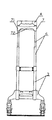
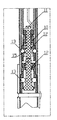
図1、図2の様に、本実用新案ラゲージキャリアーは荷台1、キャスター2、車体3及びハンドル4を含み、荷台1両端にネジ5各一個で車体3と連結し、車輪2二個をそれぞれ車体3の下方にあるキャスター21に取り付けます。ハンドル4と車体3が三段式多段伸縮パイプ6で連結されています。
As shown in FIGS. 1 and 2, the utility model luggage carrier includes a loading platform 1, a caster 2, a vehicle body 3 and a handle 4, and is connected to the vehicle body 3 with one
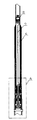
三段パイプ6の上に開閉装置7が設けられています。開閉装置7は三段パイプ6の上端に取り付けられ、開閉装置7は開閉台71と開閉ボタン72で構成され、その開閉ボタン72は三段パイプ6内にあるロックバー8と連結しています。図5、6に示すように、各段のパイプはパイプ栓10で連結され、内側パイプ内にはフック9が設けられ、内側パイプのパイプ栓内にパーツ11があり、それはフック9を通じてロックバー8と固定して連結しています; 各パイプのパイプ栓10内にはバネ1 2とボール13が設けられ、パーツ11に形成された環状凸台15とパイプ栓10の上方の間にバネ1 2は置かれています。ボール13はパイプ栓の壁に開けた穴内と、パーツ環状凸台15の上に置かれています。上記で述べた環状凸台15の断面は梯形となります。
An open / close device 7 is provided on the three-stage pipe 6. The opening / closing device 7 is attached to the upper end of the three-stage pipe 6, and the opening / closing device 7 includes an opening / closing stand 71 and an opening /
外側パイプの壁には、パイプ栓壁穴位置に対応する穴14があり、穴14の直径はボール13より小さいです。
The wall of the outer pipe has a
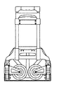
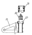
図4に示すように、各キャスター21上には螺旋型ギア23が設けられ、その螺旋ギア23の中にはバネ22が嵌められ、そして車体の上に取り付けている旋回パイプ31はその螺旋型ギア23に連動しています。
As shown in FIG. 4, a
図3に示した様に、本実用新案が折り畳んだ状態で手で荷台1を開けると、荷台と車体3が展開され、同時にネジ5が一定のカーブを持つため、キャスターは駆動されます。これに連れまして、螺旋型ギア23内のバネ22は圧縮されます。車体に固定された旋回パイプ31がある為、螺旋型ギア23は旋回パイプ31の回転方向に沿ってキャスターを連動することにより、図2に示すようなキャスター展開は実現出来ます。
As shown in Fig. 3, when the utility model is folded and the loading platform 1 is opened by hand, the loading platform and the vehicle body 3 are unfolded, and at the same time, the
三段式伸縮パイプの高さを調整する時、開閉装置の開閉ボタン72を上方向に握ると、ロックバー8は上に移動し、フック9はパイプ栓10の中のパーツ11を連動するため、バネ1 2は圧縮され、パイプ栓10内のボール13二個は引っ張られ、そして環状凸台15下方の凹位置に戻ります。この際、ボール13はパイプ栓10とパイプの連結箇所から離れ、多段パイプはこれで適切な位置迄伸びることが可能になりました。開閉ボタン72を手放すと、バネ1 2の弾力作用によって、梯形環状凸台15は、ボール13が外側パイプ壁上に設けた穴14に転落するまで、ボール13を外側パイプ壁に押し続けます。穴14の直径はボール13より小さい為、ボール13は確実に穴14内に引っかかり、結局多段パイプの長さ調整は実現できたわけです。
When adjusting the height of the three-stage telescopic pipe, if the opening /
本実用新案はコンパクトで操作及び携帯にも便利であって、構造もしっかりしているので、様々な場合に適用できます。 This utility model is compact, convenient to operate and carry, and has a solid structure, so it can be applied in various cases.
1 荷台
2 キャスター
3 車体
4 ハンドル
5 ネジ
1 Loading platform 2 Caster 3 Car body 4
Claims (7)
2. The luggage carrier according to claim 1, wherein a helical gear is provided on each caster, a spring is fitted in the helical gear, and a swivel pipe mounted on the vehicle body is interlocked with the helical gear. A luggage carrier that is characterized by
Applications Claiming Priority (1)
| Application Number | Priority Date | Filing Date | Title |
|---|---|---|---|
| CN 200420044750 CN2693588Y (en) | 2004-04-13 | 2004-04-13 | Luggage van |
Publications (1)
| Publication Number | Publication Date |
|---|---|
| JP2005297952A true JP2005297952A (en) | 2005-10-27 |
Family
ID=34775334
Family Applications (1)
| Application Number | Title | Priority Date | Filing Date |
|---|---|---|---|
| JP2005073187A Pending JP2005297952A (en) | 2004-04-13 | 2005-03-15 | Luggage carrier |
Country Status (2)
| Country | Link |
|---|---|
| JP (1) | JP2005297952A (en) |
| CN (1) | CN2693588Y (en) |
Cited By (11)
| Publication number | Priority date | Publication date | Assignee | Title |
|---|---|---|---|---|
| WO2008106455A1 (en) * | 2007-02-28 | 2008-09-04 | Dst Output | Hinged and bifurcated cart document handling apparatus utilized with a lazy-portrait document printing system |
| US8004717B2 (en) | 2006-07-25 | 2011-08-23 | Dst Output | Stack flipping document handling system for utilization with printing lazy-portrait formatted documents |
| US8235641B2 (en) | 2006-07-25 | 2012-08-07 | Dst Output | Hinged and bifurcated cart document handling apparatus utilized with a lazy-portrait document printing system |
| US8274691B1 (en) | 2006-07-25 | 2012-09-25 | Dst Output | Lazy-portrait narrow-edge-to-narrow-edge document printing system |
| US8416450B2 (en) | 2006-07-25 | 2013-04-09 | Dst Output | Turn-bar document handling apparatus for utilization with a lazy-portrait document printing system |
| US8437014B2 (en) | 2006-07-25 | 2013-05-07 | Dst Output | Paper handling system for utilization with a lazy-portrait formatting document printing system |
| JP2013237431A (en) * | 2012-05-11 | 2013-11-28 | Yee Shiuann Enterprise Co Ltd | Handcart |
| KR20150140628A (en) * | 2014-05-11 | 2015-12-16 | 조원상 | Carrier with folding wheels |
| US9888752B2 (en) | 2012-07-09 | 2018-02-13 | Royalty Bugaboo Gmbh | Luggage item, a luggage item system, a luggage item adaptor |
| US10130150B2 (en) | 2013-10-03 | 2018-11-20 | Royalty Bugaboo Gmbh | Luggage assembly and a frame |
| KR102092513B1 (en) * | 2018-11-20 | 2020-03-23 | 조원상 | Rod rotating mechanism |
Families Citing this family (3)
| Publication number | Priority date | Publication date | Assignee | Title |
|---|---|---|---|---|
| CN201427494Y (en) * | 2009-07-31 | 2010-03-24 | 简世坤 | Trundle folding device |
| CN107878645A (en) * | 2017-10-23 | 2018-04-06 | 浙江好来喜儿童用品有限公司 | A kind of handle of perambulator, tugboat accommodating mechanism |
| CN208278139U (en) * | 2018-05-28 | 2018-12-25 | 广东顺和工业有限公司 | A kind of novel three-wheeled structure trolley |
Citations (6)
| Publication number | Priority date | Publication date | Assignee | Title |
|---|---|---|---|---|
| JPH037903A (en) * | 1989-03-14 | 1991-01-16 | Fujitsu Ltd | Semiconductor optical waveguide |
| JPH0325511A (en) * | 1989-06-22 | 1991-02-04 | Fanuc Ltd | Teaching data generating system and working speed control system for numerical controller |
| JPH0338447A (en) * | 1989-07-05 | 1991-02-19 | Fujitsu Ten Ltd | Wiper controller |
| JPH0364499A (en) * | 1989-08-01 | 1991-03-19 | Mitsubishi Materials Corp | Multistage plating barrel |
| JPH0853068A (en) * | 1994-08-10 | 1996-02-27 | Ace Kk | Portable cart |
| JPH08244617A (en) * | 1995-03-10 | 1996-09-24 | Shinwa Sangyo Kk | Cart |
-
2004
- 2004-04-13 CN CN 200420044750 patent/CN2693588Y/en not_active Expired - Lifetime
-
2005
- 2005-03-15 JP JP2005073187A patent/JP2005297952A/en active Pending
Patent Citations (6)
| Publication number | Priority date | Publication date | Assignee | Title |
|---|---|---|---|---|
| JPH037903A (en) * | 1989-03-14 | 1991-01-16 | Fujitsu Ltd | Semiconductor optical waveguide |
| JPH0325511A (en) * | 1989-06-22 | 1991-02-04 | Fanuc Ltd | Teaching data generating system and working speed control system for numerical controller |
| JPH0338447A (en) * | 1989-07-05 | 1991-02-19 | Fujitsu Ten Ltd | Wiper controller |
| JPH0364499A (en) * | 1989-08-01 | 1991-03-19 | Mitsubishi Materials Corp | Multistage plating barrel |
| JPH0853068A (en) * | 1994-08-10 | 1996-02-27 | Ace Kk | Portable cart |
| JPH08244617A (en) * | 1995-03-10 | 1996-09-24 | Shinwa Sangyo Kk | Cart |
Cited By (12)
| Publication number | Priority date | Publication date | Assignee | Title |
|---|---|---|---|---|
| US8004717B2 (en) | 2006-07-25 | 2011-08-23 | Dst Output | Stack flipping document handling system for utilization with printing lazy-portrait formatted documents |
| US8235641B2 (en) | 2006-07-25 | 2012-08-07 | Dst Output | Hinged and bifurcated cart document handling apparatus utilized with a lazy-portrait document printing system |
| US8274691B1 (en) | 2006-07-25 | 2012-09-25 | Dst Output | Lazy-portrait narrow-edge-to-narrow-edge document printing system |
| US8416450B2 (en) | 2006-07-25 | 2013-04-09 | Dst Output | Turn-bar document handling apparatus for utilization with a lazy-portrait document printing system |
| US8437014B2 (en) | 2006-07-25 | 2013-05-07 | Dst Output | Paper handling system for utilization with a lazy-portrait formatting document printing system |
| WO2008106455A1 (en) * | 2007-02-28 | 2008-09-04 | Dst Output | Hinged and bifurcated cart document handling apparatus utilized with a lazy-portrait document printing system |
| JP2013237431A (en) * | 2012-05-11 | 2013-11-28 | Yee Shiuann Enterprise Co Ltd | Handcart |
| US9888752B2 (en) | 2012-07-09 | 2018-02-13 | Royalty Bugaboo Gmbh | Luggage item, a luggage item system, a luggage item adaptor |
| US10130150B2 (en) | 2013-10-03 | 2018-11-20 | Royalty Bugaboo Gmbh | Luggage assembly and a frame |
| KR20150140628A (en) * | 2014-05-11 | 2015-12-16 | 조원상 | Carrier with folding wheels |
| KR101661447B1 (en) * | 2014-05-11 | 2016-10-04 | 조원상 | Carrier with folding wheels |
| KR102092513B1 (en) * | 2018-11-20 | 2020-03-23 | 조원상 | Rod rotating mechanism |
Also Published As
| Publication number | Publication date |
|---|---|
| CN2693588Y (en) | 2005-04-20 |
Similar Documents
| Publication | Publication Date | Title |
|---|---|---|
| JP2005297952A (en) | Luggage carrier | |
| US4733681A (en) | Combination device of umbrella and golf ball retriever | |
| US20110193313A1 (en) | Foldable bicycle | |
| JP3123505U (en) | Tent folding rod assembly | |
| US6390107B1 (en) | Double-story umbrella | |
| US20260035028A1 (en) | Stroller frame and stroller | |
| US6070602A (en) | Opening structure of a multiple folded umbrella | |
| CN102303677A (en) | Bicycle folding handlebar | |
| CN108175221A (en) | A kind of structure that can be folded entirely | |
| CN205891119U (en) | Folding structure of scooter | |
| CN212828899U (en) | Scooter locomotive and have front fork of this locomotive | |
| CN201604682U (en) | Foldable unlocking device of foldable baby stroller | |
| CN108263540A (en) | A kind of scooter folding mechanism and its application method | |
| US20080053498A1 (en) | Sunshade that is expanded and folded quickly | |
| CN101773324B (en) | Folding retractable sun umbrella for car | |
| CN206681518U (en) | Sliding door door lock | |
| CN204077944U (en) | The blocking device that a kind of vehicle are folding | |
| CN203058619U (en) | Umbrella middle bar spring mechanism of multi-folding automatic opening-folding umbrella | |
| CN210363922U (en) | Portable and convenient-to-use foldable shopping cart | |
| JP4459799B2 (en) | Towing conveyor | |
| CN107100455A (en) | Sliding door door lock | |
| CN200992833Y (en) | Spring fixing device for telescopic pipe | |
| CN203127025U (en) | Anti-theft seat cushion for bicycle | |
| CN202635844U (en) | Automatic opening-closing multifold umbrella easy to fold | |
| CN2495180Y (en) | luggage trolley rod |
Legal Events
| Date | Code | Title | Description |
|---|---|---|---|
| A621 | Written request for application examination |
Free format text: JAPANESE INTERMEDIATE CODE: A621 Effective date: 20080201 |
|
| A711 | Notification of change in applicant |
Free format text: JAPANESE INTERMEDIATE CODE: A711 Effective date: 20080723 |
|
| A521 | Written amendment |
Effective date: 20080723 Free format text: JAPANESE INTERMEDIATE CODE: A821 |
|
| A977 | Report on retrieval |
Effective date: 20100415 Free format text: JAPANESE INTERMEDIATE CODE: A971007 |
|
| A131 | Notification of reasons for refusal |
Free format text: JAPANESE INTERMEDIATE CODE: A131 Effective date: 20100420 |
|
| A601 | Written request for extension of time |
Free format text: JAPANESE INTERMEDIATE CODE: A601 Effective date: 20100716 |
|
| A602 | Written permission of extension of time |
Free format text: JAPANESE INTERMEDIATE CODE: A602 Effective date: 20100722 |
|
| A521 | Written amendment |
Free format text: JAPANESE INTERMEDIATE CODE: A523 Effective date: 20100816 |
|
| A131 | Notification of reasons for refusal |
Free format text: JAPANESE INTERMEDIATE CODE: A131 Effective date: 20110208 |
|
| A02 | Decision of refusal |
Effective date: 20110712 Free format text: JAPANESE INTERMEDIATE CODE: A02 |