JP4459799B2 - Towing conveyor - Google Patents

Towing conveyor Download PDF

Info

Publication number
JP4459799B2
JP4459799B2 JP2004364614A JP2004364614A JP4459799B2 JP 4459799 B2 JP4459799 B2 JP 4459799B2 JP 2004364614 A JP2004364614 A JP 2004364614A JP 2004364614 A JP2004364614 A JP 2004364614A JP 4459799 B2 JP4459799 B2 JP 4459799B2
Authority
JP
Japan
Prior art keywords
lock
pipe
diameter portion
slider
ball
Prior art date
Legal status (The legal status is an assumption and is not a legal conclusion. Google has not performed a legal analysis and makes no representation as to the accuracy of the status listed.)
Expired - Fee Related
Application number
JP2004364614A
Other languages
Japanese (ja)
Other versions
JP2006168562A (en
Inventor
眞吾 岩本
Original Assignee
株式会社バンガード
Priority date (The priority date is an assumption and is not a legal conclusion. Google has not performed a legal analysis and makes no representation as to the accuracy of the date listed.)
Filing date
Publication date
Application filed by 株式会社バンガード filed Critical 株式会社バンガード
Priority to JP2004364614A priority Critical patent/JP4459799B2/en
Publication of JP2006168562A publication Critical patent/JP2006168562A/en
Application granted granted Critical
Publication of JP4459799B2 publication Critical patent/JP4459799B2/en
Expired - Fee Related legal-status Critical Current
Anticipated expiration legal-status Critical

Links

Images

Description

本発明は牽引運搬装置に関するものであり、より詳細にはハンドカートやキャリーケースなどの牽引によって推進させる手動の運搬装置に関するものである。   The present invention relates to a traction conveyance device, and more particularly, to a manual conveyance device driven by traction such as a hand cart or a carry case.

従来、複数のパイプ体をテレスコープ状に連結して伸縮自在に形成される引き棹を備えた牽引運搬装置としては、特許文献1や特許文献2に記載されたものが知られている。これらの従来例において牽引運搬装置はカートであり、引き棹は、一対の支柱の上端を把手で連結して形成され、各支柱が径の異なる基端側のパイプ、中間のパイプ、および先端のパイプをテレスコープ状に連結して形成されることにより内周側のパイプを外周側のパイプ内部に収容し、あるいは外周側のパイプ外部に繰り出すことによって伸縮自在に形成される。   2. Description of the Related Art Conventionally, as a traction conveyance device provided with a pulling rod that is formed to be telescopically connected by connecting a plurality of pipe bodies in a telescope shape, those described in Patent Document 1 and Patent Document 2 are known. In these conventional examples, the towing and transporting device is a cart, and the pulling rod is formed by connecting the upper ends of a pair of struts with a handle, and each strut has a proximal end pipe, an intermediate pipe, and a distal end having different diameters. By forming the pipes in a telescopic manner, the pipe on the inner peripheral side is accommodated inside the pipe on the outer peripheral side, or is extended and retracted by drawing it out of the pipe on the outer peripheral side.

また、カート使用時における引き棹の長さを維持するために、先端のパイプと中間のパイプのそれぞれの下端部には係止手段が設けられ、中間のパイプと基端側のパイプのそれぞれの上端部には孔部が設けられる。上記係止手段は、パイプの径方向に移動自在な金属球と、大径部と小径部を備えてパイプの長手方向に移動自在なピン状の進退部材とを有し、進退部材の大径部によって金属球を上記孔部内に押し出すことにより先端パイプと中間パイプ、中間パイプと基端パイプの相対移動を規制し、引き棹を伸長姿勢に維持する。加えてこの進退部材がスプリングによって金属球に大径部を対峙させる位置に付勢されることにより、伸長に伴って金属球が孔部に弾発係止し、ワンタッチで引き棹が伸長姿勢に保持される。   Further, in order to maintain the length of the pulling rod when the cart is used, a locking means is provided at the lower end of each of the leading pipe and the intermediate pipe, and each of the intermediate pipe and the proximal pipe is provided. A hole is provided in the upper end. The locking means includes a metal ball that is movable in the radial direction of the pipe, and a pin-like advance / retreat member that includes a large diameter portion and a small diameter portion and is movable in the longitudinal direction of the pipe. By pushing the metal ball into the hole by the portion, the relative movement of the tip pipe and the intermediate pipe, the intermediate pipe and the base pipe is restricted, and the pulling rod is maintained in the extended posture. In addition, the advancing / retracting member is urged to a position where the large-diameter portion is opposed to the metal ball by the spring, so that the metal ball is elastically locked in the hole as it is extended, and the pulling lever is in the extended posture with one touch. Retained.

さらに、遠隔操作によって引き棹の縮退を可能にするために、先端パイプ内部の中空部には線材が挿通され、引き棹の上部には操作体が設けられる。上記線材は一端が操作体に、他端が先端パイプに設けられた係止手段の進退部材に連結され、操作体が操作されると大径部によって金属球を孔部内に押し出していた進退部材を上方に移動させ、金属球に小径部を対峙させる。したがってこの状態で引き棹を上方から押し下げると、金属球が孔部から退避して先端パイプを中間パイプ内部へと収容することが可能で、また、これに伴って先端パイプの進退部材が中間パイプの進退部材を押圧して下方に移動させることにより、中間パイプの進退部材の金属球との接点が大径部から小径部に変化して中間パイプが基端パイプ内部へと移動可能になる。
特開平8-53068号公報 特開平8-244617号公報
Further, in order to allow the pulling rod to be retracted by remote operation, a wire is inserted into the hollow portion inside the tip pipe, and an operating body is provided above the pulling rod. One end of the wire is connected to the operating body, the other end is connected to the advancing / retracting member of the locking means provided on the tip pipe, and when the operating body is operated, the advancing / retreating member pushes the metal ball into the hole by the large diameter portion Is moved upward, and the small-diameter portion is opposed to the metal ball. Therefore, if the pulling rod is pushed down from above in this state, the metal ball can be retracted from the hole and the tip pipe can be accommodated inside the intermediate pipe. By pressing the advancing / retracting member and moving it downward, the contact point of the advancing / retreating member of the intermediate pipe with the metal ball changes from the large diameter portion to the small diameter portion, so that the intermediate pipe can move into the proximal pipe.
JP-A-8-53068 JP-A-8-244617

しかしながら、上述した第1、第2従来例においては、係止手段によって維持できる引き棹の長さが上記伸長姿勢の一態様のみであるために、カート使用者の身長などによってはカートが牽引しづらくなる場合がある。   However, in the above-described first and second conventional examples, the length of the pulling rod that can be maintained by the locking means is only one aspect of the above-mentioned extended posture, so that the cart is pulled depending on the height of the cart user. It may be difficult.

本発明は以上の欠点を解消すべくなされたものであって、使い勝手の良好な牽引運搬装置の提供を目的とする。   The present invention has been made to solve the above drawbacks, and an object of the present invention is to provide a traction transportation device that is easy to use.

本発明によれば上記目的は、
三段以上からなるテレスコープ状にパイプ体1を連結して伸縮自在に形成される引き棹2と、
パイプ体1に固定されて引き棹2内部に収容され、伸長に伴って隣接するパイプ体1、1を相対移動不能に弾発係止して引き棹2を縮退不能に保持するロック体3の複数とを有し、
前記ロック体3は、細径部23aと大径部23bを備えてパイプ体1の長手方向に移動自在なスライダ23によりロック球25をパイプ体1の径方向に移動自在に形成され、引き棹2の伸長姿勢において上段側に配置される各パイプ体1(1A、1B)の下端部に固定されて下段側に配置される各パイプ体1(1B、1C)の上端部に形成されたロック孔21に前記ロック球25を係止して隣接するパイプ体1、1(1A、1B、あるいは1B、1C)を縮退不能に保持するとともに、前記スライダ23は圧縮スプリング28により大径部23bによってロック球25をロック孔21内に押し出す位置に付勢され、
最上段位置のロック体3’のスライダ23は前記引き棹2に形成された操作レバー19に線状体26を介して連結され、前記操作レバー19の操作によりスライダ23を移動させてロック球25に細径部23aを合わせて最上段位置のロック体3’を係止解除して引き棹2を上方から縮退させることによって該ロック体3’より下段に位置するロック体3”のスライダ23を前記圧縮スプリング28に抗してロック球25に細径部23aを合わせるように押し下げて係止解除操作可能で、引き棹2を縮退姿勢に移行可能に形成され、
かつ、最上段部において隣接する下段側のパイプ体1Bには調整ロック孔29、29・・が形成され、前記最上段位置のロック体3’のロック球25を調整ロック孔29に係止させることによって該ロック体3’より下段に位置するロック体3”の非係止解除操作範囲内において複数の相対位置で前記最上段部において隣接するパイプ体1A、1Bを拘束可能に形成され、引き棹2の長さを調節可能な牽引運搬装置を提供することにより達成される。
According to the present invention, the object is
A pulling rod 2 that is formed to be telescopically formed by connecting the pipe body 1 in a telescope shape having three or more stages,
A lock body 3 which is fixed to the pipe body 1 and accommodated in the pull rod 2 and elastically locks the adjacent pipe bodies 1 and 1 so as not to move relative to each other, and holds the pull rod 2 in a non-degenerate state. A plurality of
The lock body 3 includes a small diameter portion 23a and a large diameter portion 23b, and a lock ball 25 is formed to be movable in the radial direction of the pipe body 1 by a slider 23 that is movable in the longitudinal direction of the pipe body 1. The lock formed on the upper end portion of each pipe body 1 (1B, 1C) fixed to the lower end portion of each pipe body 1 (1A, 1B) arranged on the upper stage side in the extended posture 2 The lock ball 25 is engaged with the hole 21 to hold the adjacent pipe body 1, 1 (1A, 1B, or 1B, 1C) in a non-degenerate manner, and the slider 23 is compressed by a large diameter portion 23b by a compression spring 28. The lock ball 25 is urged to a position where the lock ball 25 is pushed into the lock hole 21,
The slider 23 of the lock body 3 ′ at the uppermost position is connected to an operation lever 19 formed on the pulling rod 2 via a linear body 26, and the slider 23 is moved by the operation of the operation lever 19 to move the lock ball 25. The slider 23 of the lock body 3 ″ positioned below the lock body 3 ′ is brought into contact with the small diameter portion 23a by releasing the lock body 3 ′ at the uppermost position and retracting the pulling rod 2 from above. The lock spring 25 can be pushed down so as to match the small diameter portion 23a against the compression spring 28 and can be unlocked, and the pull rod 2 can be shifted to a retracted posture .
And, adjusting the locking holes 29, 29 ... on the lower side of the pipe body 1B adjacent Oite the uppermost portion is formed, engaging the locking ball 25 of the locking member 3 uppermost position 'to adjust the lock hole 29 By being stopped , the pipe bodies 1A and 1B adjacent to each other at the uppermost step portion are formed to be constrained at a plurality of relative positions within the non-engagement release operation range of the lock body 3 ″ located below the lock body 3 ′. This is achieved by providing a traction and conveying device in which the length of the pulling rod 2 can be adjusted.

本発明によれば、牽引運搬装置は、最上段位置のロック体3’により、すなわち、最内周側に配置されて引き棹2の最上段に位置するパイプ体1Aに固定され、該パイプ体1Aあるいは隣接する二段目のパイプ体1Bの中空部に収容されて伸長姿勢の引き棹2において最上段に位置するロック体3’により、上記最上段のパイプ体1Aと該パイプ体1の外周側に隣接する二段目のパイプ体1Bとを複数の相対位置で拘束することによって引き棹2の全長を調節可能に形成される。引き棹2の長さを調節するためには伸長に伴って弾発係止するロック体3を係止解除する必要があるが、引き棹2を縮退する際に適宜係止解除される上記最上段のロック体3’を利用することにより、縮退時と同様の操作をするだけで引き棹2の長さを調節することが可能になり、使いやすくすることができる。また、最上段のロック体3’による最上段部に隣接するパイプ体1A、1Bの拘束を除いては上述した従来例に特段改造を加えたり、変更したりする必要がないことから、従来例の構造を利用して、引き棹2伸長・縮退時の操作を何ら変更することなく、簡単に引き棹2を長さ調節可能にすることができる。   According to the present invention, the towing and transporting device is fixed to the pipe body 1A located at the innermost peripheral side and positioned at the uppermost stage of the pulling rod 2 by the lock body 3 'at the uppermost position, The uppermost pipe body 1A and the outer circumference of the pipe body 1 are accommodated in the hollow portion of 1A or the adjacent second-stage pipe body 1B and positioned at the uppermost stage in the extended pulling lever 2 By constraining the second-stage pipe body 1B adjacent to the side at a plurality of relative positions, the overall length of the pulling rod 2 can be adjusted. In order to adjust the length of the pull rod 2, it is necessary to unlock the lock body 3 that is elastically locked as it extends, but when the pull rod 2 is retracted, the lock body 3 is appropriately unlocked. By using the upper lock body 3 ′, it is possible to adjust the length of the pulling lever 2 only by performing the same operation as in the degeneracy, which makes it easy to use. Further, since there is no need to make any special modification or change to the above-described conventional example except for the restraint of the pipe bodies 1A, 1B adjacent to the uppermost part by the uppermost locking body 3 ′, the conventional example By using this structure, it is possible to easily adjust the length of the pulling rod 2 without changing the operation at the time of extending / retracting the pulling rod 2.

上記最上段位置のロック体3’による引き棹2の長さ調節は、例えば、上述した二段目のパイプ体1Bに長手方向に沿って複数の孔を設けてロック体3’を係止する孔を選択できるようにして行うことが可能であり、従来例同様に遠隔操作可能な操作部を引き棹2の上部に設ければ、楽な操作によってロック体3’を係止解除でき、あるいは係止させたくない孔に対して妄りに係止しないようにすることができる。さらに、上記二段目のパイプ体1Bの長さは、カートの携行性を考慮して適宜決定される引き棹2の縮退姿勢における長さにほぼ一致するために、引き棹2の全長の調節に適した特定の長さの範囲を設定することができる The length adjustment of the pulling rod 2 by the lock body 3 ′ at the uppermost position is performed by, for example, providing a plurality of holes along the longitudinal direction in the second-stage pipe body 1B and locking the lock body 3 ′. It is possible to perform the operation so that the hole can be selected, and if the operation unit that can be remotely operated is provided on the upper part of the pulling rod 2 as in the conventional example, the lock body 3 ′ can be unlocked by an easy operation, or It is possible to prevent the holes that are not desired to be locked from being loosely locked. Further, the length of the second-stage pipe body 1B substantially matches the length in the retracted posture of the pulling rod 2 that is appropriately determined in consideration of the portability of the cart. It is possible to set a specific length range suitable for .

したがって本発明によれば、テレスコープ構造により引き棹2を縮退時にコンパクトにすることができ、携帯性が高められるとともに、引き棹2内部に収容されるロック体3によって上記携帯性を損ねることなく使用時の長さを調節でき、使い勝手を良好にすることができる。   Therefore, according to the present invention, the pulling lever 2 can be made compact when retracted by the telescope structure, and the portability is enhanced, and the portability is not impaired by the lock body 3 housed inside the pulling rod 2. The length during use can be adjusted, and usability can be improved.

また、以上においては引き棹2の長さを調節できること、すなわち使用状態としての引き棹2の長さを調整できることにより牽引運搬装置の使い勝手を高める場合を示したが、テレスコープ構造により伸縮自在に形成される引き棹2の不使用状態における携行性をより高めることによって、牽引運搬装置の使い勝手を向上させることもできる。すなわち、上述した従来例は、引き棹2を縮退姿勢に保持できないために、持ち運びに注意を要するという欠点がある。   In the above, the case where the length of the pulling rod 2 can be adjusted, that is, the length of the pulling rod 2 as a use state can be adjusted to improve the usability of the towing and transportation device. Usability of the towing and transporting device can be improved by further improving the portability of the pulling rod 2 to be formed when not in use. That is, the above-described conventional example has a drawback in that it needs to be taken with care because the pulling rod 2 cannot be held in the retracted posture.

この発明はかかる欠点を解消すべくなされたものであって、携行性を高めることによって使い勝手に優れたカートの提供を目的とするもので、
三段以上からなるテレスコープ状にパイプ体1を連結して伸縮自在に形成される引き棹2と、
パイプ体1に固定されて引き棹2内部に収容され、伸長に伴って隣接するパイプ体1、1を相対移動不能に弾発係止して引き棹2を縮退不能に保持するロック体3の複数とを有し、
前記ロック体3は、細径部23aと大径部23bを備えてパイプ体1の長手方向に移動自在なスライダ23によりロック球25をパイプ体1の径方向に移動自在に形成され、引き棹2の伸長姿勢において上段側に配置される各パイプ体1(1A、1B)の下端部に固定されて下段側に配置される各パイプ体1(1B、1C)の上端部に形成されたロック孔21に前記ロック球25を係止して隣接するパイプ体1、1(1A、1B、あるいは1B、1C)を縮退不能に保持するとともに、前記スライダ23は圧縮スプリング28により大径部23bによってロック球25をロック孔21内に押し出す位置に付勢され、
最上段位置のロック体3’のスライダ23は前記引き棹2に形成された操作レバー19に線状体26を介して連結され、前記操作レバー19の操作によりスライダ23を移動させてロック球25に細径部23aを合わせて最上段位置のロック体3’を係止解除して引き棹2を上方から縮退させることによって該ロック体3’より下段に位置するロック体3”のスライダ23を前記圧縮スプリング28に抗してロック球25に細径部23aを合わせるように押し下げて係止解除操作可能で、引き棹2を縮退姿勢に移行可能に形成され、
最上段部において隣接する下段側のパイプ体1Bには下端部にもロック孔21が形成され、かつ、前記引き棹2の伸長姿勢において下段側に配置される残余の各パイプ体1(1C)には下端部に第2のロック孔21’が形成されるとともに、前記最上段位置より下段の各ロック体3”は、スライダ23に前記細径部23aおよび大径部23bと天地を逆にした第2の細径部23a’および第2の大径部23b’を備え、前記圧縮スプリング28に抗して第2のロック球25’を前記第2の大径部23b’により前記第2のロック孔21’に係止して引き棹2を縮退姿勢に保持する牽引運搬装置を提供するものである。
The present invention has been made to eliminate such drawbacks, and aims to provide a cart that is easy to use by improving portability.
A pull rod 2 Shin be reduced freely formed by connecting the pipe 1 to the telescopic to a three or more stages,
A lock body 3 which is fixed to the pipe body 1 and accommodated in the pull rod 2 and elastically locks the adjacent pipe bodies 1 and 1 so as not to move relative to each other, and holds the pull rod 2 in a non-degenerate state. A plurality of
The lock body 3 includes a small diameter portion 23a and a large diameter portion 23b, and a lock ball 25 is formed to be movable in the radial direction of the pipe body 1 by a slider 23 that is movable in the longitudinal direction of the pipe body 1. The lock formed on the upper end portion of each pipe body 1 (1B, 1C) fixed to the lower end portion of each pipe body 1 (1A, 1B) arranged on the upper stage side in the extended posture 2 The lock ball 25 is engaged with the hole 21 to hold the adjacent pipe body 1, 1 (1A, 1B, or 1B, 1C) in a non-degenerate manner, and the slider 23 is compressed by a large diameter portion 23b by a compression spring 28. The lock ball 25 is urged to a position where the lock ball 25 is pushed into the lock hole 21,
The slider 23 of the lock body 3 ′ at the uppermost position is connected to an operation lever 19 formed on the pulling rod 2 via a linear body 26, and the slider 23 is moved by the operation of the operation lever 19 to move the lock ball 25. The slider 23 of the lock body 3 ″ positioned below the lock body 3 ′ is brought into contact with the small diameter portion 23a by releasing the lock body 3 ′ at the uppermost position and retracting the pulling rod 2 from above. The lock spring 25 can be pushed down so as to match the small diameter portion 23a against the compression spring 28 and can be unlocked, and the pull rod 2 can be shifted to a retracted posture.
The lower pipe body 1B adjacent to the uppermost stage part is formed with a lock hole 21 at the lower end part, and the remaining pipe bodies 1 (1C) arranged on the lower stage side in the extended posture of the pulling rod 2 A second lock hole 21 ′ is formed at the lower end of each of the lock bodies 3 ″ below the uppermost position so that the slider 23 has the small-diameter portion 23 a and the large-diameter portion 23 b opposite to the top and bottom. The second small-diameter portion 23a ′ and the second large-diameter portion 23b ′ are provided, and the second lock ball 25 ′ is opposed to the compression spring 28 by the second large-diameter portion 23b ′. engaged with the lock hole 21 'is intended to provide a pull conveyor that holds the pull rod 2 to degenerate position.

この発明によれば、テレスコープ構造により伸縮自在に形成されて携帯性に優れた引き棹2をロック手段4によって縮退姿勢に保持することができる。したがって、引き棹2の妄りな伸長を防止することができるために、例えば引き棹2上部に形成される把手を握るなどして牽引運搬装置を持ち運ぶことができ、より携行性を高めることができる。   According to the present invention, the pulling rod 2 which is telescopically formed and can be extended and contracted and has excellent portability can be held in the contracted posture by the locking means 4. Accordingly, since it is possible to prevent the pulling rod 2 from being unreasonably stretched, the traction conveyance device can be carried by holding a handle formed on the upper portion of the pulling rod 2, for example, and the portability can be further improved. .

ロック手段4は引き棹2を縮退姿勢に保持できれば足り、例えばネジ止めによって構成することも可能であるが、上述した従来例等のように弾発係止する係止手段と孔部等を用いた場合には操作性を高めることができる The lock means 4 is sufficient if it can hold the pulling rod 2 in a retracted posture, and can be configured by screwing, for example. However, as in the conventional example described above, the locking means and the hole are used. If it is, the operability can be improved .

一方、引き棹2を伸長姿勢にも保持できるようにすれば荷物の運搬をより安定させることが可能であり、この場合において引き棹2の縮退・伸長姿勢の保持を同一のロック手段4によって行えば、引き棹2の構造を単純化でき、牽引運搬装置の製造コスト等を低減することができる。また、ロック手段4を引き棹2内部、すなわちパイプ体1の中空部に収容した場合には、外観がスマートになり、より携行性を向上させることができる。   On the other hand, if the pulling rod 2 can be held in the extended posture, it is possible to stabilize the transportation of the load. In this case, the pulling rod 2 is held in the contracted / extended posture by the same locking means 4. For example, the structure of the pulling rod 2 can be simplified, and the manufacturing cost and the like of the traction conveyance device can be reduced. Further, when the lock means 4 is housed inside the pulling rod 2, that is, in the hollow portion of the pipe body 1, the appearance becomes smart and the portability can be further improved.

一方、パイプ体1を三段以上に連結して構成する場合においては、最上段位置より下段に位置するロック体3”、すなわち従来例における中間パイプの係止手段等によって中間パイプと基端パイプなどの隣接するパイプを縮退状態にも保持できるようにしなければならない上に、この係止手段を引き棹2伸長時に解除操作できるようにしなければならなくなる。したがって、最上段位置より下段に位置するロック体3”についても個々に係止、係止解除操作できるように構成すればよいが、例えば後述する実施の形態に詳述するように、最上段位置のロック体3’によって最上段部に隣接するパイプ体1A、1Bを縮退状態に保持したときに、最上段位置より下段のロック体3”が付勢力に抗して隣接するパイプ体1、1を縮退状態に保持するように構成すれば、操作性をより向上させることができる。   On the other hand, in the case where the pipe body 1 is configured to be connected in three or more stages, the intermediate pipe and the proximal pipe are provided by the locking body 3 ″ positioned below the uppermost position, that is, the locking means of the intermediate pipe in the conventional example. In addition, it is necessary to be able to hold the adjacent pipes in a contracted state, and to release the locking means when the pulling lever 2 is extended, so that it is positioned below the uppermost position. The lock body 3 ″ may be configured so that it can be individually locked and unlocked. For example, as will be described in detail in an embodiment described later, the lock body 3 ′ is moved to the uppermost portion by the lock body 3 ′ at the uppermost position. When the adjacent pipe bodies 1A, 1B are held in the contracted state, the lock body 3 "below the uppermost position holds the adjacent pipe bodies 1, 1 in the contracted state against the biasing force. By configuring so, it is possible to further improve the operability.

以上の説明から明らかなように、本発明によれば、引き棹の長さを調節できることにより、使い勝手の良好な牽引運搬装置を提供することができる。   As can be seen from the above description, according to the present invention, it is possible to provide an easy-to-use traction / transport device by adjusting the length of the pulling rod.

また、引き棹を縮退姿勢に保持できることにより、使い勝手の良好な牽引運搬装置を提供することができる。   In addition, since the pulling rod can be held in the contracted posture, it is possible to provide a traction transport device that is easy to use.

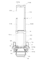
図1に本発明の実施の形態を示す。この実施の形態において、牽引運搬装置はハンドカートであり、一対の支柱10、10の上端部を把手11で連結して形成される引き棹2と、該引き棹2の下端部に連結される荷台12および車輪13を有する。   FIG. 1 shows an embodiment of the present invention. In this embodiment, the towing and transporting device is a hand cart, and is connected to a pull rod 2 formed by connecting upper ends of a pair of support columns 10 and 10 with a handle 11, and a lower end portion of the pull rod 2. It has a loading platform 12 and wheels 13.

上記支柱10は、図1および図2に示すように、上段パイプ1A、中段パイプ1B、下段パイプ1Cの3本の金属からなるパイプ(パイプ体1)を有し、上段パイプ1Aの外径が中段パイプ1Bの内径によりもやや小さく、中段パイプ1Bの外径が下段パイプ1Cの内径よりもやや小さく形成されることにより、上段パイプ1Aの外周側に中段パイプ1Bが、中段パイプ1Bの外周側に下段パイプ1Cが配置されれて図5に示す縮退姿勢から図1や図2に示す伸長姿勢まで三段からなるテレスコープ状に伸縮自在に形成される。また、上段パイプ1Aや中段パイプ1Bを内周側のパイプ1とし、中段パイプ1Bや下段パイプ1Cを外周側のパイプ1としたときの内外周パイプ1、1間の伸長方向における相対移動範囲を規制するために、上記内周側をなす上段パイプ1A等の下端にはキャップ14が固定され、上記外周側をなす中段パイプ1B等の上端部にはストッパ部15が形成される。   As shown in FIGS. 1 and 2, the column 10 has a pipe (pipe body 1) made of three metals, that is, an upper pipe 1A, a middle pipe 1B, and a lower pipe 1C. The outer diameter of the upper pipe 1A is as follows. The middle pipe 1B is slightly smaller than the inner diameter of the middle pipe 1B, and the outer diameter of the middle pipe 1B is slightly smaller than the inner diameter of the lower pipe 1C, so that the middle pipe 1B is located on the outer circumference side of the upper pipe 1A, and the outer circumference side of the middle pipe 1B. The lower pipe 1C is arranged in a telescopic shape having three stages from the retracted position shown in FIG. 5 to the extended position shown in FIGS. Further, the relative movement range in the extending direction between the inner and outer pipes 1 and 1 when the upper pipe 1A and the middle pipe 1B are used as the inner pipe 1 and the middle pipe 1B and the lower pipe 1C is used as the outer pipe 1 is shown. In order to regulate, a cap 14 is fixed to the lower end of the upper pipe 1A or the like that forms the inner peripheral side, and a stopper portion 15 is formed at the upper end of the middle pipe 1B or the like that forms the outer peripheral side.

キャップ14は、図2等に示すように、パイプ1の中空部に差し込まれる細径の挿入部14aの下方にパイプ1の外部に突出する太径の張出部14bを備えた段付き円柱形状に形成され、上記上段パイプ1A等の下端に挿入部14aを嵌合させて該パイプ1A等の下端を適宜かしめることなどによって固定される。張出部14bは、装着される内周側のパイプ1外径よりも大きく、かつ、外周側のパイプ1の内径よりも小さい外径を有し、上記上段パイプ1A等の下端に外周側に突出する段部を形成する。また、ストッパ部15は、内周側のパイプ1の外径よりも大きく、かつ、上記張出部14bの外径よりも小さい程度の内径を備えるように外周側のパイプ1上端部を内方に突出させて形成される。このストッパ部15は、図2等に示すように、中段パイプ1Bにおいてはパイプ1内径方向に突出する段部を上端部に一体形成することにより、下段パイプ1Cにおいてはその上端部に固定される補強部材16により形成される。なお、上記補強部材16は両支柱10、10を下段パイプ1C、1Cの上端部において相互に連結して当該位置における支柱10、10の間隔を維持する機能を果たすもので、合成樹脂材により形成されて図示しないネジ等により各支柱10の下段パイプ1Cの上端部に固定される。   As shown in FIG. 2 and the like, the cap 14 has a stepped columnar shape having a large-diameter overhanging portion 14b projecting outside the pipe 1 below the thin-diameter insertion portion 14a inserted into the hollow portion of the pipe 1. And is fixed by fitting the insertion portion 14a to the lower end of the upper pipe 1A or the like and caulking the lower end of the pipe 1A or the like as appropriate. The overhanging portion 14b has an outer diameter that is larger than the outer diameter of the pipe 1 on the inner peripheral side to be mounted and smaller than the inner diameter of the pipe 1 on the outer peripheral side. A protruding step is formed. Further, the stopper portion 15 has the inner end of the pipe 1 on the outer peripheral side inward so as to have an inner diameter that is larger than the outer diameter of the pipe 1 on the inner peripheral side and smaller than the outer diameter of the overhanging portion 14b. It is formed by protruding. As shown in FIG. 2 and the like, the stopper portion 15 is fixed to the upper end portion of the lower pipe 1C by integrally forming a step portion protruding in the inner diameter direction of the pipe 1 at the upper end portion in the intermediate pipe 1B. It is formed by the reinforcing member 16. The reinforcing member 16 functions to maintain the distance between the columns 10 and 10 at the positions by connecting the columns 10 and 10 to each other at the upper ends of the lower pipes 1C and 1C, and is formed of a synthetic resin material. Then, it is fixed to the upper end portion of the lower pipe 1C of each support column 10 with screws or the like (not shown).

したがって支柱10はキャップ14がストッパ部15に衝接するまで伸長することが可能であり、衝接時において最大伸長状態となる。なお、支柱10の縮退方向については、下段パイプ1Cに外嵌されるエンドキャップ15によって下段パイプ1Cの下端が閉塞されることにより、中段パイプ1Bの下段パイプ1Cより下方への移動が禁止され、移動範囲が規制される。   Therefore, the support column 10 can be extended until the cap 14 comes into contact with the stopper portion 15, and is in a maximum extended state at the time of contact. As for the contraction direction of the support column 10, the lower end of the lower pipe 1C is closed by the end cap 15 fitted around the lower pipe 1C, so that the lower pipe 1C is prohibited from moving downward from the lower pipe 1C. The movement range is restricted.

把手11は、図2等に示すように、両端部に上段パイプ1Aの上端部が嵌入される連結開口18aを備えて中空状に形成され、両支柱10、10の上端部の間隔を拘束するケース体18を有する。ケース体18は、合成樹脂材を射出成形して形成される図示しない上ケース片と下ケース片をネジ止めして形成され、かかるネジ止めのためにケース体18にはボス18bが設けられる。このケース体18は、ハンドカート牽引時に握りやすいように、支柱10への連結状態において下部側が長手方向ほぼ中央部を中心に全体的に膨らむようにして曲面処理され、この曲面処理の中心部分には後述する操作レバー19へのアクセスを可能にする操作用開口18cが開設される。   As shown in FIG. 2 and the like, the handle 11 is formed in a hollow shape with connecting openings 18a into which the upper end portions of the upper pipe 1A are fitted at both ends, and restrains the interval between the upper end portions of both the columns 10 and 10. A case body 18 is provided. The case body 18 is formed by screwing an upper case piece and a lower case piece (not shown) formed by injection molding a synthetic resin material, and the case body 18 is provided with a boss 18b for such screwing. The case body 18 is curved so that the lower side of the case body 18 is swollen as a whole about the center in the longitudinal direction in the connected state to the support column 10 so as to be easily gripped when towing the hand cart. Is opened with an operation opening 18c that allows access to an operation lever 19 to be described later.

荷台12は、図1に示すように、上述した従来例とほぼ同様の枠状部材であり、金属のパイプをコ字形状に屈曲して形成される主枠12aと、主枠12aに対して垂直回転自在に連結される補助枠12bおよび脚片12cを有する。主枠12aは、前述したエンドキャップ15を貫通する棒状の回転軸20に自由端側を軸支されて引き棹2に対して垂直回転自在で、引き棹2に対してほぼ直角をなす水平姿勢と、引き棹2に沿う垂直姿勢との間を回転することができる。補助枠12bおよび脚片12cは、棒状の金属線材の中央部をほぼ凸状に屈曲させてクランクシャフト状に形成され、両端が主枠12aに連結される。上記補助枠12bは回転によって主枠12aの荷受け部分を拡張するもので、平面視において凸状部分が主枠12aの内方に収納される収納姿勢と主枠12aから突出する拡張姿勢とに変化する。また、脚片12cは車輪13とともに荷台12の荷受け部分を水平に支えるもので、主枠12aが水平姿勢をとるときに凸状部分が主枠12aから下方へと突出する支承姿勢をとり、主枠12aの垂直姿勢において凸状部分が主枠12aに沿う収納姿勢をとる。   As shown in FIG. 1, the loading platform 12 is a frame-like member that is substantially the same as the conventional example described above, and a main frame 12 a formed by bending a metal pipe into a U-shape, and a main frame 12 a It has the auxiliary | assistant frame 12b and the leg piece 12c connected so that vertical rotation is possible. The main frame 12a is supported at the free end side by the rod-shaped rotary shaft 20 that penetrates the end cap 15 described above, and can rotate vertically with respect to the pulling rod 2 and is in a horizontal position that is substantially perpendicular to the pulling rod 2. And a vertical posture along the pulling rod 2 can be rotated. The auxiliary frame 12b and the leg piece 12c are formed in a crankshaft shape by bending the central portion of the rod-shaped metal wire into a substantially convex shape, and both ends are connected to the main frame 12a. The auxiliary frame 12b expands the load receiving portion of the main frame 12a by rotation, and the plan view changes into a storage posture in which the convex portion is stored inside the main frame 12a and an extended posture protruding from the main frame 12a. To do. Further, the leg piece 12c supports the load receiving portion of the loading platform 12 together with the wheels 13, and when the main frame 12a takes a horizontal posture, the convex portion takes a support posture in which the main frame 12a protrudes downward from the main frame 12a. In the vertical posture of the frame 12a, the convex portion takes the storage posture along the main frame 12a.

車輪13も従来例とほぼ同様で、上述したエンドキャップ15に回転自在に支持される車軸13aの両端にゴムタイヤ13bを取り付けて形成され、二個のゴムタイヤ13bを連結した単一車軸に形成される。このゴムタイヤ13bは一対の支柱10、10を外方から挟み付けるように引き棹2の両側方に配置され、主枠12aに載せた荷物とゴムタイヤ13bとの接触を避け、安定して荷物を運搬しやすくするために、上述した主枠12aからゴムタイヤ13bの上方にかけて水平姿勢をとる主枠12aと支柱10に沿うようにL字状に屈曲するタイヤカバー枠12dが延設される。   The wheel 13 is substantially the same as the conventional example, and is formed by attaching rubber tires 13b to both ends of an axle 13a rotatably supported by the end cap 15 described above, and is formed on a single axle connecting two rubber tires 13b. . The rubber tires 13b are arranged on both sides of the pulling rod 2 so as to sandwich the pair of support columns 10 and 10 from the outside, and avoid the contact between the load placed on the main frame 12a and the rubber tire 13b, and stably transport the load. In order to facilitate this, a main frame 12a that takes a horizontal posture from the main frame 12a to the upper side of the rubber tire 13b and a tire cover frame 12d that is bent in an L shape so as to extend along the column 10 are extended.

したがって、ゴムタイヤ13b、13bと脚片12cによって支えられて水平姿勢をとる主枠12aや補助枠12b等に荷物を載せ、引き棹2を傾けると、引き棹2やタイヤカバー枠12d、12dに背中をもたれるようにして荷物が二本のゴムタイヤ13b、13dによって二点支持され、この状態で引き棹2を牽引することにより車輪13によって荷物を楽に運搬することができる。また、荷物を運搬しないときには、引き棹2を縮退させ、主枠12aを垂直姿勢にすることにより、荷台12とほぼ同程度の大きさにハンドカートを折り畳むことができる。さらに、前述したエンドキャップ15にはゴムタイヤ13bの底面と同じ高さまで下方に突出する支持片15aが設けられるため、上記折り畳んだ状態においてゴムタイヤ13b、13bと支持片15a、15aの四点支持によってハンドカートを自立させることができ、より収納性が高められる。なお、この支持片15aは平面視において車軸13aに対して荷台12側の偏心した位置に配置されるためにハンドカート牽引時に地面等と接触することはない。   Therefore, when a load is placed on the main frame 12a or the auxiliary frame 12b which is supported by the rubber tires 13b and 13b and the leg pieces 12c and takes a horizontal posture and the pulling lever 2 is tilted, the back of the pulling rod 2 and the tire cover frames 12d and 12d The luggage is supported at two points by the two rubber tires 13b, 13d so that the luggage can be easily transported by the wheels 13 by pulling the pulling rod 2 in this state. Further, when the luggage is not transported, the hand cart can be folded to approximately the same size as the loading platform 12 by retracting the pulling lever 2 and bringing the main frame 12a into a vertical posture. Further, since the end cap 15 is provided with a support piece 15a that protrudes downward to the same height as the bottom surface of the rubber tire 13b, the handpiece is supported by four-point support of the rubber tires 13b and 13b and the support pieces 15a and 15a in the folded state. A cart can be made self-supporting, and a storage property is improved more. Since the support piece 15a is arranged at an eccentric position on the loading platform 12 side with respect to the axle 13a in plan view, it does not come into contact with the ground or the like when towing the hand cart.

また、この実施の形態において、上述した引き棹2を伸長姿勢や縮退姿勢に保持できるようにするために、支柱10内部にはロック手段4が収容され、把手11はロック手段4を解除操作可能な上述した操作レバー19を備える。ロック手段4は、前述したキャップ14によって上段パイプ1Aや中段パイプ1Bの下端部に取り付けられるロック体3と、上記外周側のパイプ1をなす中段パイプ1Bや下段パイプ1Cに穿孔されるロック孔21とを有し、ロック体3をロック孔21に係止させることにより内外周のパイプ1、1間における相対移動を規制して引き棹2を伸長・縮退姿勢に保持する。   Further, in this embodiment, in order to be able to hold the pulling rod 2 described above in the extended posture or the retracted posture, the lock means 4 is accommodated in the support column 10, and the handle 11 can be operated to release the lock means 4. The above-described operation lever 19 is provided. The lock means 4 includes a lock body 3 attached to the lower ends of the upper pipe 1A and the middle pipe 1B by the cap 14, and a lock hole 21 drilled in the middle pipe 1B and the lower pipe 1C forming the outer pipe 1. The lock body 3 is engaged with the lock hole 21 to restrict relative movement between the inner and outer pipes 1 and 1 so that the pulling rod 2 is held in the extended / retracted posture.

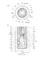
ロック体3は、図2等に示すように、キャップ14に設けられるスライダガイド孔22内に挿入されるスライダ23と、ロック球ガイド孔24内に保持されるロック球25とを有し、上記スライダガイド孔22はパイプ1の長手方向に沿って形成され、上記ロック球ガイド孔24はスライダガイド孔22からパイプ1の外周までパイプ1の径方向に伸びるようにして形成される。   As shown in FIG. 2 and the like, the lock body 3 includes a slider 23 inserted into a slider guide hole 22 provided in the cap 14, and a lock ball 25 held in the lock ball guide hole 24. The slider guide hole 22 is formed along the longitudinal direction of the pipe 1, and the lock ball guide hole 24 is formed so as to extend from the slider guide hole 22 to the outer periphery of the pipe 1 in the radial direction of the pipe 1.

スライダ23は、細径部23aと太径部23bを備えた合成樹脂材からなる段付きピンであり、段付きのスライダガイド孔22に挿入されて引き棹2長手方向に移動可能で、移動によりスライダガイド孔22に連通するロック球ガイド孔24に対して細径部23aと太径部23bのいずれかを面する。一方、ロック球25は、ロック球ガイド孔24の長さよりもやや大きい直径を備えた金属製の球状体であり、ロック球ガイド孔24に挿入されてパイプ1の径方向に移動可能に保持され、スライダ23がロック球ガイド孔24に太径部23bを面したときにロック球ガイド孔24からその一部が外部に押し出され、細径部を面したときにロック球ガイド孔24およびスライダガイド孔22内に収容される。したがって、スライダ23をパイプ長手方向、すなわち上方あるいは下方に移動させることにより、ロック球25をキャップ14内に収容し、あるいはキャップ14外方に突出させることができ、外周側のパイプ1に形成されるロック孔21にロック球25を係脱させることができる。なお、図2等に示すように、スライダ23は、上段パイプ1Aに取り付けられるロック体3’においては後述する線状体26により、中段パイプ1Bに取り付けられるロック体3”においては抜け止めピン27によりスライダガイド孔22から抜け止めされる。   The slider 23 is a stepped pin made of a synthetic resin material having a small diameter portion 23a and a large diameter portion 23b. The slider 23 is inserted into the stepped slider guide hole 22 and can move in the longitudinal direction of the pulling lever 2. Either the small diameter portion 23a or the large diameter portion 23b faces the lock ball guide hole 24 communicating with the slider guide hole 22. On the other hand, the lock sphere 25 is a metal spherical body having a diameter slightly larger than the length of the lock sphere guide hole 24, and is inserted into the lock sphere guide hole 24 so as to be movable in the radial direction of the pipe 1. When the slider 23 faces the lock ball guide hole 24 with the large diameter portion 23b, a part thereof is pushed out from the lock ball guide hole 24, and when the slider 23 faces the small diameter portion, the lock ball guide hole 24 and the slider guide It is accommodated in the hole 22. Therefore, by moving the slider 23 in the longitudinal direction of the pipe, that is, upward or downward, the lock ball 25 can be accommodated in the cap 14 or protrude outward from the cap 14, and formed on the pipe 1 on the outer peripheral side. The lock ball 25 can be engaged with and disengaged from the lock hole 21. As shown in FIG. 2 and the like, the slider 23 is provided with a pin 27 for the lock body 3 ″ attached to the middle pipe 1B by the linear body 26 described later in the lock body 3 ′ attached to the upper pipe 1A. This prevents the slider guide hole 22 from coming off.

一方、ロック孔21は、ロック球25よりやや小さい直径を備え、ロック球25の突出によって引き棹2を伸長・縮退姿勢に保持できるように、外周側のパイプ1の上下端部に形成される。すなわち、ロック球25を備えたロック体3が固定される上段パイプ1A等の下端部とロック孔21が穿孔される中段パイプ1B等の上端部がロックされることにより引き棹2の伸長姿勢が維持され、上段パイプ1A等と中段パイプ1B等のそれぞれの下端部がロックされることにより引き棹2の縮退姿勢が保持される。   On the other hand, the lock hole 21 has a slightly smaller diameter than the lock ball 25 and is formed at the upper and lower ends of the outer pipe 1 so that the pulling rod 2 can be held in an extended / retracted posture by the protrusion of the lock ball 25. . That is, when the lower end portion of the upper stage pipe 1A or the like to which the lock body 3 having the lock ball 25 is fixed and the upper end part of the middle stage pipe 1B or the like in which the lock hole 21 is drilled are locked, the extension posture of the pull rod 2 is increased. The lower end of each of the upper pipe 1A and the middle pipe 1B is locked, and the retracted posture of the pull rod 2 is maintained.

また、伸縮に伴ってワンタッチで引き棹2を伸縮姿勢に保持できるように、上記スライダ23は、圧縮スプリング28によって付勢されるとともに、傾斜面23cを備えて形成される。上記圧縮スプリング28は、図2等に示すように、スライダ23とキャップ14に両端を保持されてロック球25に太径部23bを対峙させる方向にスライダ23を付勢する。一方傾斜面23cは、ロック球25がロック孔21内に進入できないときにスライダ23の細径部23aがロック球25に面するように圧縮スプリング23の付勢力に抗してスライダ23を移動させる分力を生じさせ、あるいは、ロック球25がロック孔21に面したときに上記圧縮スプリング28の付勢力によってロック球25をパイプ体1外部に押し出す分力を生じさせるように細径部23aから太径部23bに向かって漸次直径を大きくするようにして形成される。したがってロック孔21がロック球ガイド孔24に対峙しないときには、外周側のパイプ1に移動を規制されたロック球25が細径部23aに面するように圧縮スプリング28の付勢力に抗してスライダ23を移動させ、対峙に伴って傾斜面23cによりロック球25をキャップ14外部に押し出すことにより、引き棹2の伸長に伴ってロック体3をロック孔21に弾発係止することができる。   Further, the slider 23 is urged by the compression spring 28 and formed with an inclined surface 23c so that the pulling rod 2 can be held in the expansion / contraction posture with one touch in accordance with expansion / contraction. As shown in FIG. 2 and the like, the compression spring 28 urges the slider 23 in a direction in which both ends are held by the slider 23 and the cap 14 and the lock ball 25 faces the large-diameter portion 23b. On the other hand, the inclined surface 23c moves the slider 23 against the urging force of the compression spring 23 so that the narrow diameter portion 23a of the slider 23 faces the lock ball 25 when the lock ball 25 cannot enter the lock hole 21. From the small diameter portion 23a, a component force is generated or a component force is generated to push the lock ball 25 out of the pipe body 1 by the biasing force of the compression spring 28 when the lock ball 25 faces the lock hole 21. It is formed so that the diameter gradually increases toward the large diameter portion 23b. Therefore, when the lock hole 21 does not face the lock ball guide hole 24, the slider 50 resists the urging force of the compression spring 28 so that the lock ball 25 whose movement is restricted by the pipe 1 on the outer peripheral side faces the small diameter portion 23 a. 23, and the lock ball 25 is pushed out of the cap 14 by the inclined surface 23c along with the opposing surface, so that the lock body 3 can be elastically locked to the lock hole 21 as the pulling rod 2 extends.

一方、ロック球25をロック孔21に対して係止解除するために、上記把手11は、ケース体18内部に上述した操作レバー19を収容して形成される。操作レバー19は、図2等に示すように、上述した操作用開口18cからケース体18外部に押圧操作可能に露出するボタン部19aと、このボタン部19aの両端からケース体18の連結開口18aに臨む程度まで延設される一対のアーム部19b、19bとを有し、このアーム部19bには上述したボス18bが貫通するガイド開口19cが開設されてケース体18に対して操作レバー19を上下方向に摺動自在に連結する。なお、ボタン部19aの下部、すなわちケース体18から露出する部位は、ケース体18と連続するように曲面に形成される。   On the other hand, in order to release the lock ball 25 from the lock hole 21, the handle 11 is formed by accommodating the operation lever 19 described above inside the case body 18. As shown in FIG. 2 and the like, the operation lever 19 includes a button portion 19a exposed to the outside of the case body 18 through the operation opening 18c described above, and a connection opening 18a of the case body 18 from both ends of the button portion 19a. The arm portion 19b is provided with a pair of arm portions 19b and 19b, and the arm portion 19b has a guide opening 19c through which the boss 18b described above is opened. Connect slidably in the vertical direction. Note that a lower portion of the button portion 19 a, that is, a portion exposed from the case body 18 is formed in a curved surface so as to be continuous with the case body 18.

また、上記操作レバー19への操作によってロック球25を係止解除するために、上段パイプ1A内部の中空部には線状体26が収容される。線状体26は一端部がアーム部19bに他端部が上段パイプ1Aに取り付けられるスライダ23に連結されて操作レバー19への操作力を上段パイプ1Aのスライダ23に伝達し、該スライダ23を上下動させてロック球25に対して太径部23bを面した状態から細径部23aに面した状態にする、すなわちロック球25をロック孔21から退避可能な状態にする。   Further, in order to unlock the lock ball 25 by operating the operation lever 19, a linear body 26 is accommodated in the hollow portion inside the upper pipe 1A. The linear body 26 is connected to the slider 23 attached at one end to the arm 19b and at the other end to the upper pipe 1A to transmit the operating force to the operating lever 19 to the slider 23 of the upper pipe 1A. By moving up and down, the lock ball 25 is moved from the state facing the large diameter part 23 b to the state facing the small diameter part 23 a, that is, the lock ball 25 is retracted from the lock hole 21.

以上のロック手段4と操作レバー19を備えるこの実施の形態においては、図2および図3(a)に示すように、把手11を握り込むようにボタン部19aを上方に押し込むことによって操作レバー19を操作できるようにするために、上段パイプ1Aのロック体(最上段位置のロック体3’)のスライダ23’は圧縮スプリング28によって下方に付勢され、ボタン部19aの押し込みによる線状体26の上方移動により上方に移動することによってロック球25に細径部23aを面するように形成される。したがって操作レバー19への操作により上段パイプ1Aのロック体3’を係止解除すれば、あとはそのまま引き棹2を上方から押し下げることにより、ロック孔21の周縁でロック球25を押圧してキャップ14内部に退避させ、上段パイプ1Aを中段パイプ1B内部の中空部に収容することができる。   In this embodiment provided with the locking means 4 and the operation lever 19 as described above, as shown in FIGS. 2 and 3A, the operation lever 19 is pushed by pushing the button portion 19a upward so as to grasp the handle 11. The slider 23 'of the lock body (the lock body 3' at the uppermost position) of the upper pipe 1A is urged downward by the compression spring 28, and the linear body 26 is pushed by pushing the button portion 19a. The lock ball 25 is formed so as to face the small-diameter portion 23a by moving upward by the upward movement. Therefore, if the lock body 3 ′ of the upper pipe 1 A is released by operating the operation lever 19, the lock ball 25 is pressed by the peripheral edge of the lock hole 21 by pushing down the pulling rod 2 from the upper side as it is. 14, the upper pipe 1A can be accommodated in a hollow portion inside the middle pipe 1B.

一方、中段パイプ1Bに取り付けられるロック体(最上段位置のロック体3’より下段に位置するロック体3”)は、上記上段パイプ1Aの中段パイプ1Bに対する降下によって係止解除できるように、スライダ23”が上方に付勢され、上段パイプ1Aのキャップ14に押し下げられることによりロック球25に細径部23aを面するように形成される。したがって図3(b)に示すように、上段パイプ1Aの収容完了に伴って中段パイプ1Bのロック体3”が係止解除されるために、引き棹2をそのまま上方から押し下げてゆくだけで、今度は中段パイプ1Bを下段パイプ1C内部に収容することができる。   On the other hand, the lock body (the lock body 3 ″ positioned below the uppermost lock body 3 ′) attached to the middle pipe 1B can be unlocked by being lowered with respect to the middle pipe 1B of the upper pipe 1A. 23 ″ is urged upward and is pushed down by the cap 14 of the upper pipe 1A, so that the lock ball 25 is formed so as to face the small diameter portion 23a. Therefore, as shown in FIG. 3B, the lock body 3 ″ of the middle pipe 1B is released when the upper pipe 1A is completely accommodated. This time, the middle pipe 1B can be accommodated inside the lower pipe 1C.

さらに、このように引き棹2を縮退してゆく場合において、操作レバー19の操作を解除しておけば、今度は上段パイプ1Aのロック体3’が中段パイプ1B下端部のロック孔21に弾発係止して上段パイプ1Aと中段パイプ1Bの縮退状態が維持される。一方、このとき中段パイプ1Bはエンドキャップ15によって降下が規制されて下段パイプ1Cとの間で縮退状態となり、また、中段パイプ1Bのロック体3”は、上段パイプ1Aのキャップ14とエンドキャップ15の間に挟まれるようにして圧縮され、上述同様ロック球25が細径部23aに対峙するようにスライダ23”が押し下げられた状態となる。このため、かかる押し下げられた状態において中段パイプ1Bと下段パイプ1Cの縮退状態を保持するために、ロック手段4は、中段パイプ1Bのロック体3”のスライダ23”に第2の細径部23a’、第2の太径部23b’および第2の傾斜面23c’を備えるとともに、上記ロック体3”に第2のロック球25’を備え、また、中段パイプ1Bには第2のロック球ガイド孔24’が設けられ、下段パイプ1Cには上記第2のロック球25’に係止する第2のロック孔21’が設けられる。   Further, in the case where the pulling rod 2 is retracted in this way, if the operation of the operation lever 19 is released, the lock body 3 'of the upper pipe 1A is now elastically inserted into the lock hole 21 at the lower end of the middle pipe 1B. As a result, the upper pipe 1A and the middle pipe 1B are maintained in the degenerated state. On the other hand, at this time, the lower pipe 1B is regulated by the end cap 15 so that the lower pipe 1B is in a contracted state with the lower pipe 1C, and the lock body 3 ″ of the middle pipe 1B includes the cap 14 and the end cap 15 of the upper pipe 1A. The slider 23 ″ is pushed down so that the lock ball 25 faces the small diameter portion 23a as described above. For this reason, in order to maintain the contracted state of the intermediate pipe 1B and the lower pipe 1C in such a depressed state, the locking means 4 has a second small diameter portion 23a on the slider 23 ″ of the lock body 3 ″ of the intermediate pipe 1B. ', The second large diameter portion 23b' and the second inclined surface 23c ', the lock body 3 "is provided with a second lock ball 25', and the middle pipe 1B has a second lock ball. A guide hole 24 ′ is provided, and a second lock hole 21 ′ that engages with the second lock ball 25 ′ is provided in the lower pipe 1 </ b> C.

上記第2の太径部23b’、第2の細径部23a’、第2の傾斜面23c’、第2のロック球25’、第2のロック球ガイド孔24’、および第2のロック孔21’は、図5および図6に示すように、上述した太径部23b、細径部23a、ロック球25、ロック球ガイド孔24およびロック孔21に対して干渉しないようにスライダ23”の軸周りに直交方向に配置され、また、第2の太径部23b’と第2の細径部23a’は天地を逆にして形成される。したがって、上述したように中段パイプ1Bのロック体3”が押し下げられると、第2のロック球25’に第2の太径部23b’が対峙し、第2のロック球25’が第2のロック孔21’に係止して中段パイプ1Bと下段パイプ1Cの相対移動が規制され、中段パイプ1Bと下段パイプ1Cが縮退状態に拘束される。この拘束解除は操作レバー19によって上段パイプ1Aのロック体3’を係止解除して引き棹2を上方に引き延ばし、上段パイプ1Aのキャップ14の上昇によって中段パイプ1Bのロック体3”を圧縮状態から開放してスプリング28の弾性復帰力によってスライダ23”を上方に移動させることにより行うことが可能で、これにより第2のロック球25’に第2の細径部23a’が対峙して第2のロック球25’がキャップ14内に収容される。なお、第2の太径部23b’と第2の細径部23a’は上述同様傾斜面23cを介して形成されるために、引き棹2の伸長に伴って第2のロック球25’に第2の細径部23aが対峙するようにスムーズにスライダ23”が移動し、あるいは引き棹2の縮退に伴ってスムーズに第2のロック球25’が第2のロック孔21’に係止する。   The second large diameter portion 23b ', the second small diameter portion 23a', the second inclined surface 23c ', the second lock ball 25', the second lock ball guide hole 24 ', and the second lock As shown in FIGS. 5 and 6, the hole 21 ′ has a slider 23 ″ so as not to interfere with the aforementioned large diameter portion 23 b, small diameter portion 23 a, lock ball 25, lock ball guide hole 24, and lock hole 21. The second large-diameter portion 23b 'and the second small-diameter portion 23a' are formed upside down, so that the lock of the intermediate pipe 1B as described above. When the body 3 ″ is pushed down, the second large-diameter portion 23b ′ faces the second lock ball 25 ′, and the second lock ball 25 ′ engages with the second lock hole 21 ′, so that the middle pipe The relative movement of 1B and lower pipe 1C is restricted, and middle pipe 1B and lower pipe 1C is restrained degeneratively. To release the restraint, the lock body 3 'of the upper pipe 1A is unlocked by the operating lever 19 and the pulling rod 2 is extended upward, and the lock body 3 "of the middle pipe 1B is compressed by raising the cap 14 of the upper pipe 1A. And the slider 23 ″ is moved upward by the elastic return force of the spring 28, whereby the second small diameter portion 23a ′ is opposed to the second lock ball 25 ′. Two lock balls 25 ′ are accommodated in the cap 14. Since the second large-diameter portion 23b ′ and the second small-diameter portion 23a ′ are formed via the inclined surface 23c as described above, the second lock ball 25 ′ is formed along with the extension of the pulling rod 2. The slider 23 "moves smoothly so that the second small diameter portion 23a faces each other, or the second lock ball 25 'smoothly engages with the second lock hole 21' as the pulling rod 2 retracts. To do.

加えて、この実施の形態において、カートは、全長を調節できるように、上述した中段パイプ1Bの上下端部のロック孔21、21の間に、該ロック孔21とほぼ同寸法の複数の調節ロック孔29、29・・を備える。この調節ロック孔29は、引き棹2を伸長状態と縮退状態に保持するロック孔21、21の中間において上段パイプ1Aのロック体3’を係止させることにより中段パイプ1Bからの上段パイプ1Aの引き出し量を調整し、引き棹2の全長の調節を可能にするもので、図4に示すように中段パイプ1Bの長手方向に等ピッチで複数設けられる。このため、上段パイプ1Aのロック体3’を任意の調節ロック孔29に係止させることにより、中段パイプ1Bの長さを利用して引き棹2の全長を調節することができる。   In addition, in this embodiment, the cart has a plurality of adjustments having substantially the same dimensions as the lock holes 21 between the lock holes 21, 21 at the upper and lower ends of the intermediate pipe 1B so that the overall length can be adjusted. Provided with lock holes 29, 29,. The adjustment lock hole 29 is provided between the middle pipe 1B and the upper pipe 1A by engaging the lock body 3 'of the upper pipe 1A in the middle of the lock holes 21 and 21 for holding the pull rod 2 in the extended state and the retracted state. The pull-out amount is adjusted so that the overall length of the pull rod 2 can be adjusted. As shown in FIG. 4, a plurality of the pull-up rods 2 are provided at equal pitches in the longitudinal direction of the intermediate pipe 1B. For this reason, by engaging the lock body 3 ′ of the upper pipe 1 </ b> A with the arbitrary adjustment lock hole 29, the overall length of the pulling rod 2 can be adjusted using the length of the middle pipe 1 </ b> B.

したがって、以上のカートは、図5に示すように、縮退姿勢において、上段パイプ1A下端部のロック体3’が中段パイプ1B下端部のロック孔21に係止するとともに、中段パイプ1B下端部のロック体3”が下段パイプ1C下端部のロック孔21に係止することにより、引き棹2の全長を拘束することができ、携帯時に引き棹2が妄りに伸長することはなく、この状態で把手11を握って運搬することもできる。この状態から引き棹2を伸長させるには、把手11の操作ボタン部19aを押圧すればよく、これにより上段パイプ1Aのロック体3’が中段パイプ1B下端部のロック孔21に対して係止解除され、上段パイプ1Aを中段パイプ1B内部から引き出すことができ、さらに、中段パイプ1Bからの上段パイプ1Aの引き出しによって中段パイプ1Bのロック体3”がスプリング28の弾性復帰力によって係止解除され、連動して中段パイプ1Bを下段パイプ1Cから引き出すことができる。   Accordingly, as shown in FIG. 5, in the above-described cart, in the retracted position, the lock body 3 ′ at the lower end of the upper pipe 1A is engaged with the lock hole 21 at the lower end of the middle pipe 1B, and at the lower end of the middle pipe 1B. By locking the lock body 3 ″ in the lock hole 21 at the lower end of the lower pipe 1C, the full length of the pull rod 2 can be constrained, and the pull rod 2 does not stretch unnaturally when being carried. It can also be carried by grasping the handle 11. To extend the pulling rod 2 from this state, it is only necessary to press the operation button portion 19a of the handle 11, whereby the lock body 3 'of the upper pipe 1A is moved to the middle pipe 1B. The upper pipe 1A can be pulled out from the inside of the middle pipe 1B, and the upper pipe 1A can be pulled out from the middle pipe 1B. What locking body 3 'of the middle pipe 1B are unlocked by the elastic restoring force of the spring 28, it can be drawn middle pipe 1B from the lower pipe 1C in conjunction with each other.

また、この後、把手11を引き上げて引き棹2を伸長させれば、中段パイプ1Bのロック体3”は今度は下段パイプ1C上端部のロック孔21に弾発係止して中段・下段パイプ1B、1Cが伸長状態に拘束され、また、上段パイプ1Aのロック体3’は中段パイプ1Bの最下部に配置される調節ロック孔29に弾発係止するが、この状態でさらに操作ボタン部19aを押圧すれば、上段パイプ1Aのロック体3’の最下部の調節ロック孔29との係止を解除でき、そのまま把手11と操作ボタン部19aを操作して任意の調節ロック孔29、あるいは中段パイプ1B上端部のロック孔21に上段パイプ1Aのロック体3’が係止する位置まで上段パイプ1Aを中段パイプ1Bから引き出すことにより、引き棹2の長さを調節することができる。また、この状態から引き棹2を縮退姿勢に戻す場合には、再度操作ボタン部19aを押圧して引き棹2を下方に押し込むように縮めればよく、操作ボタン部19aの押圧によって上段パイプ1Aのロック体3’が係止解除されることにより上段パイプ1Aを中段パイプ1B内に収容することができる。加えて、この上段パイプ1Aの中段パイプ1Bに対する降下により中段パイプ1B下端部のロック体3”も下段パイプ1C上端部のロック孔21に対して係止解除されるために、中段パイプ1Bも下段パイプ1Cの内部に収容することができるようになり、したがって、引き棹2を上述した縮退姿勢に移行させることができる。   After that, if the handle 11 is pulled up to extend the pull rod 2, the lock body 3 "of the middle pipe 1B is now elastically locked into the lock hole 21 at the upper end of the lower pipe 1C, and the middle and lower pipes. 1B and 1C are constrained in the extended state, and the lock body 3 ′ of the upper pipe 1A is elastically locked in the adjustment lock hole 29 arranged at the lowermost part of the middle pipe 1B. If 19a is pressed, the engagement with the lowermost adjustment lock hole 29 of the lock body 3 'of the upper pipe 1A can be released, and the handle 11 and the operation button part 19a are operated as they are, or any adjustment lock hole 29 or The length of the pulling rod 2 can be adjusted by pulling the upper pipe 1A from the middle pipe 1B to the position where the lock body 3 'of the upper pipe 1A is locked in the lock hole 21 at the upper end of the middle pipe 1B. Further, when the pulling rod 2 is returned to the retracted posture from this state, it is only necessary to press the operation button portion 19a again to shrink the pulling rod 2 downward, and the upper pipe 1A is pressed by the operation button portion 19a. The upper pipe 1A can be accommodated in the middle pipe 1B by releasing the lock body 3 ', and the lower end of the middle pipe 1B is locked by the lowering of the upper pipe 1A with respect to the middle pipe 1B. Since 3 ″ is also released from the lock hole 21 at the upper end of the lower pipe 1C, the middle pipe 1B can also be accommodated inside the lower pipe 1C. It is possible to shift to a degenerated posture.

本発明を示す全体斜視図である。1 is an overall perspective view showing the present invention. 引き棹2の伸長姿勢における内部構造を示す要部断面図である。It is principal part sectional drawing which shows the internal structure in the expansion | extension attitude | position of the pulling rod 2. FIG. ロック体の係止解除時の動作を示す要部断面図で、(a)は上段パイプのロック体の動作を示す図、(b)は中段パイプのロック体の動作を示す図である。It is principal part sectional drawing which shows the operation | movement at the time of lock release of a lock body, (a) is a figure which shows operation | movement of the lock body of an upper stage pipe, (b) is a figure which shows operation | movement of the lock body of a middle stage pipe. 引き棹の全長を調節する構造を示す図である。It is a figure which shows the structure which adjusts the full length of a pull rod. 引き棹の縮退姿勢における内部構造を示す要部断面図である。It is principal part sectional drawing which shows the internal structure in the retracted posture of a pulling rod. 中段パイプのロック体によって引き棹を縮退姿勢に保持した状態を示す図で、(a)は図5の6A-6A線断面図、(b)は(a)の6B-6B線断面図である。It is a figure which shows the state which hold | maintained the pulling rod in the retracted attitude | position with the lock body of the middle stage pipe, (a) is the sectional view on the 6A-6A line of FIG. 5, (b) is the sectional view on the 6B-6B line of (a). .

符号の説明Explanation of symbols

1 パイプ体
1’ 最上段部に隣接するパイプ体
2 引き棹
3 ロック体
3’ 最上段位置のロック体
3” 下段に位置するロック体
4 ロック手段


DESCRIPTION OF SYMBOLS 1 Pipe body 1 'Pipe body adjacent to the uppermost part 2 Pulling rod 3 Locking body 3' Locking body in the uppermost position 3 "Locking body located in the lower stage 4 Locking means


Claims (3)

三段以上からなるテレスコープ状にパイプ体を連結して伸縮自在に形成される引き棹と、
パイプ体に固定されて引き棹内部に収容され、伸長に伴って隣接するパイプ体を相対移動不能に弾発係止して引き棹を縮退不能に保持するロック体の複数とを有し、
前記ロック体は、細径部と大径部を備えてパイプ体の長手方向に移動自在なスライダによりロック球をパイプ体の径方向に移動自在に形成され、引き棹の伸長姿勢において上段側に配置される各パイプ体の下端部に固定されて下段側に配置される各パイプ体の上端部に形成されたロック孔に前記ロック球を係止して隣接するパイプ体を縮退不能に保持するとともに、前記スライダは圧縮スプリングにより大径部によってロック球をロック孔内に押し出す位置に付勢され、
最上段位置のロック体のスライダは前記引き棹に形成された操作レバーに線状体を介して連結され、前記操作レバーの操作によりスライダを移動させてロック球に細径部を合わせて最上段位置のロック体を係止解除して引き棹を上方から縮退させることによって該ロック体より下段に位置するロック体のスライダを前記圧縮スプリングに抗してロック球に細径部を合わせるように押し下げて係止解除操作可能で、引き棹を縮退姿勢に移行可能に形成され、
かつ、最上段部において隣接する下段側のパイプ体には調整ロック孔が形成され、前記最上段位置のロック体のロック球を調整ロック孔に係止させることによって該ロック体より下段に位置するロック体の非係止解除操作範囲内において複数の相対位置で前記最上段部において隣接するパイプ体を拘束可能に形成され、引き棹の長さを調節可能な牽引運搬装置。
A pulling rod that is telescopically formed by connecting pipe bodies in a telescope shape consisting of three or more stages,
A plurality of lock bodies fixed to the pipe body and accommodated inside the pull rod, and elastically locking the adjacent pipe bodies so that they cannot move relative to each other as they extend, and holding the pull rod in a non-degenerate manner,
The lock body has a small diameter portion and a large diameter portion, and a lock ball is formed to be movable in the radial direction of the pipe body by a slider which is movable in the longitudinal direction of the pipe body. The lock ball is locked to a lock hole formed in the upper end portion of each pipe body that is fixed to the lower end portion of each pipe body that is arranged on the lower stage side, and the adjacent pipe bodies are held indestructible. The slider is urged to a position for pushing the lock ball into the lock hole by the large diameter portion by the compression spring,
The slider of the lock body at the uppermost position is connected to the operation lever formed on the pulling rod via a linear body, and the slider is moved by operating the operation lever so that the small diameter portion is aligned with the lock ball and the uppermost position is moved. The lock body at the position is unlocked and the pulling lever is retracted from above, so that the slider of the lock body positioned below the lock body is pushed down against the compression spring so that the small diameter portion is aligned with the lock ball. unlocking can be operated Te a, are migrated to be able to form a pull rod to degenerate attitude,
And, on the lower side of the pipe adjacent Oite the uppermost portion is adjusted lock hole is formed, the in the lower than the locking member by engaging the locking balls of the locking member of the uppermost position in the adjustment lock hole A pulling and conveying device that is formed so as to be able to restrain an adjacent pipe body at a plurality of relative positions within a plurality of relative positions within a non-engagement release operation range of the lock body, and is capable of adjusting the length of the pulling rod.
三段以上からなるテレスコープ状にパイプ体を連結して伸縮自在に形成される引き棹と、
パイプ体に固定されて引き棹内部に収容され、伸長に伴って隣接するパイプ体を相対移動不能に弾発係止して引き棹を縮退不能に保持するロック体の複数とを有し、
前記ロック体は、細径部と大径部を備えてパイプ体の長手方向に移動自在なスライダによりロック球をパイプ体の径方向に移動自在に形成され、引き棹の伸長姿勢において上段側に配置される各パイプ体の下端部に固定されて下段側に配置される各パイプ体の上端部に形成されたロック孔に前記ロック球を係止して隣接するパイプ体を縮退不能に保持するとともに、前記スライダは圧縮スプリングにより大径部によってロック球をロック孔内に押し出す位置に付勢され、
最上段位置のロック体のスライダは前記引き棹に形成された操作レバーに線状体を介して連結され、前記操作レバーの操作によりスライダを移動させてロック球に細径部を合わせて最上段位置のロック体を係止解除して引き棹を上方から縮退させることによって該ロック体より下段に位置するロック体のスライダを前記圧縮スプリングに抗してロック球に細径部を合わせるように押し下げて係止解除操作可能で、引き棹を縮退姿勢に移行可能に形成され、
最上段部において隣接する下段側のパイプ体には下端部にもロック孔が形成され、かつ、前記引き棹の伸長姿勢において下段側に配置される残余の各パイプ体には下端部に第2のロック孔が形成されるとともに、前記最上段位置より下段の各ロック体は、スライダに前記細径部および大径部と天地を逆にした第2の細径部および第2の大径部を備え、前記圧縮スプリングに抗して第2のロック球を前記第2の大径部により前記第2のロック孔に係止して引き棹を縮退姿勢に保持する牽引運搬装置。
A pull rod to be stretched or squeezed freely formed by connecting a pipe in telescopic to a three or more stages,
A plurality of lock bodies fixed to the pipe body and accommodated inside the pull rod, and elastically locking the adjacent pipe bodies so that they cannot move relative to each other as they extend, and holding the pull rod in a non-degenerate manner,
The lock body has a small diameter portion and a large diameter portion, and a lock ball is formed to be movable in the radial direction of the pipe body by a slider which is movable in the longitudinal direction of the pipe body. The lock ball is locked to a lock hole formed in the upper end portion of each pipe body that is fixed to the lower end portion of each pipe body that is arranged on the lower stage side, and the adjacent pipe bodies are held indestructible. The slider is urged to a position for pushing the lock ball into the lock hole by the large diameter portion by the compression spring,
The slider of the lock body at the uppermost position is connected to the operation lever formed on the pulling rod via a linear body, and the slider is moved by operating the operation lever so that the small diameter portion is aligned with the lock ball and the uppermost position is moved. The lock body at the position is unlocked and the pulling lever is retracted from above, so that the slider of the lock body positioned below the lock body is pushed down against the compression spring so that the small diameter portion is aligned with the lock ball. Can be unlocked and formed to be able to shift the pulling lever to a retracted position,
A lock hole is also formed at the lower end of the lower pipe body adjacent in the uppermost stage, and the remaining pipe bodies arranged on the lower stage in the extended posture of the pulling rod are second at the lower end. The lock body is formed at a position lower than the uppermost position, and the second small diameter portion and the second large diameter portion in which the small diameter portion and the large diameter portion are inverted to the top and bottom of the slider. the provided, pull conveyor that holds the pull rod engages the second locking hole by the second locking ball against the compression spring and the second large-diameter portion to degenerate position.
前記引き棹の伸長姿勢において上段側に配置される各パイプ体の下端部にはキャップが固定されて前記ロック体は該キャップに保持され、
引き棹を縮退させることによって前記最上段位置より下段の各ロック体のスライダがキャップにより押し下げられる請求項1または2記載の牽引運搬装置。
A cap is fixed to a lower end portion of each pipe body arranged on the upper side in the extending posture of the pulling rod, and the lock body is held by the cap,
The traction conveyance device according to claim 1 or 2, wherein the slider of each lock body below the uppermost position is pushed down by a cap by retracting the pull rod .
JP2004364614A 2004-12-16 2004-12-16 Towing conveyor Expired - Fee Related JP4459799B2 (en)

Priority Applications (1)

Application Number Priority Date Filing Date Title
JP2004364614A JP4459799B2 (en) 2004-12-16 2004-12-16 Towing conveyor

Applications Claiming Priority (1)

Application Number Priority Date Filing Date Title
JP2004364614A JP4459799B2 (en) 2004-12-16 2004-12-16 Towing conveyor

Publications (2)

Publication Number Publication Date
JP2006168562A JP2006168562A (en) 2006-06-29
JP4459799B2 true JP4459799B2 (en) 2010-04-28

Family

ID=36669759

Family Applications (1)

Application Number Title Priority Date Filing Date
JP2004364614A Expired - Fee Related JP4459799B2 (en) 2004-12-16 2004-12-16 Towing conveyor

Country Status (1)

Country Link
JP (1) JP4459799B2 (en)

Cited By (1)

* Cited by examiner, † Cited by third party
Publication number Priority date Publication date Assignee Title
CN108860278A (en) * 2018-03-26 2018-11-23 合肥奥彩特塑胶科技材料有限公司 A kind of connecting elements for shopping cart

Families Citing this family (2)

* Cited by examiner, † Cited by third party
Publication number Priority date Publication date Assignee Title
CN107284491A (en) * 2017-06-09 2017-10-24 孙本龙 Gather folding hand buggy
KR102361689B1 (en) * 2020-08-13 2022-02-11 (주)피티씨 Trasportation apparatus for heavy weight equipment

Cited By (2)

* Cited by examiner, † Cited by third party
Publication number Priority date Publication date Assignee Title
CN108860278A (en) * 2018-03-26 2018-11-23 合肥奥彩特塑胶科技材料有限公司 A kind of connecting elements for shopping cart
CN108860278B (en) * 2018-03-26 2020-10-16 合肥奥彩特塑胶科技材料有限公司 Connecting component for shopping cart

Also Published As

Publication number Publication date
JP2006168562A (en) 2006-06-29

Similar Documents

Publication Publication Date Title
JP5027948B2 (en) Handcart
TW593026B (en) Stroller
JP2005297952A (en) Luggage carrier
CN109303399A (en) Pull rod device and trolley luggage
US4591183A (en) Luggage carrier
US20030038007A1 (en) Telescopic handle for luggage cart
US20100254751A1 (en) Telescoping pole system
US10932539B2 (en) Operating handle device
JP2021507146A (en) Deployable equipment, especially stepping stones
JP4459799B2 (en) Towing conveyor
JP3851278B2 (en) Bag with handle and puller combined with stopper
TW202126221A (en) Collapsible adjustable height table
US20050092568A1 (en) Retractable leaning towing handle system for wheeled baggage
CN217396608U (en) Bassinet push rod unlocking device
JP2986536B2 (en) Apparatus for releasing support in portable carrier
EP3847922B1 (en) Length adjustment device
JP5202008B2 (en) suitcase
CN206119504U (en) Foldable pull rod and draw -bar box
JPH04183674A (en) Releasing device for supporting body in portable cart
JP2008272316A (en) Bag with four wheels
KR101248448B1 (en) Stroller
US7097159B1 (en) Jack pin removal device
CN213057381U (en) Telescopic structure and scooter
JPH04183673A (en) Releasing device of supporting body in portable cart
JPH042132Y2 (en)

Legal Events

Date Code Title Description
A621 Written request for application examination

Free format text: JAPANESE INTERMEDIATE CODE: A621

Effective date: 20070209

A131 Notification of reasons for refusal

Free format text: JAPANESE INTERMEDIATE CODE: A131

Effective date: 20090630

A977 Report on retrieval

Free format text: JAPANESE INTERMEDIATE CODE: A971007

Effective date: 20090630

A521 Written amendment

Free format text: JAPANESE INTERMEDIATE CODE: A523

Effective date: 20090831

Free format text: JAPANESE INTERMEDIATE CODE: A821

Effective date: 20090831

TRDD Decision of grant or rejection written
A01 Written decision to grant a patent or to grant a registration (utility model)

Free format text: JAPANESE INTERMEDIATE CODE: A01

Effective date: 20100209

A01 Written decision to grant a patent or to grant a registration (utility model)

Free format text: JAPANESE INTERMEDIATE CODE: A01

A61 First payment of annual fees (during grant procedure)

Free format text: JAPANESE INTERMEDIATE CODE: A61

Effective date: 20100210

R150 Certificate of patent or registration of utility model

Free format text: JAPANESE INTERMEDIATE CODE: R150

FPAY Renewal fee payment (event date is renewal date of database)

Free format text: PAYMENT UNTIL: 20130219

Year of fee payment: 3

FPAY Renewal fee payment (event date is renewal date of database)

Free format text: PAYMENT UNTIL: 20130219

Year of fee payment: 3

FPAY Renewal fee payment (event date is renewal date of database)

Free format text: PAYMENT UNTIL: 20140219

Year of fee payment: 4

R250 Receipt of annual fees

Free format text: JAPANESE INTERMEDIATE CODE: R250

R250 Receipt of annual fees

Free format text: JAPANESE INTERMEDIATE CODE: R250

R250 Receipt of annual fees

Free format text: JAPANESE INTERMEDIATE CODE: R250

LAPS Cancellation because of no payment of annual fees