JP2005297910A - Vehicle instrument - Google Patents
Vehicle instrument Download PDFInfo
- Publication number
- JP2005297910A JP2005297910A JP2004120571A JP2004120571A JP2005297910A JP 2005297910 A JP2005297910 A JP 2005297910A JP 2004120571 A JP2004120571 A JP 2004120571A JP 2004120571 A JP2004120571 A JP 2004120571A JP 2005297910 A JP2005297910 A JP 2005297910A
- Authority
- JP
- Japan
- Prior art keywords
- vehicle
- driver
- design
- light
- door
- Prior art date
- Legal status (The legal status is an assumption and is not a legal conclusion. Google has not performed a legal analysis and makes no representation as to the accuracy of the status listed.)
- Pending
Links
Images
Landscapes
- Details Of Measuring Devices (AREA)
- Instrument Panels (AREA)
- Illuminated Signs And Luminous Advertising (AREA)
Abstract
【課題】無駄な電力を消費することなく、運転者に対して斬新な印象を与える車両用計器を提供する。
【解決手段】車両の運転者が車両に乗車したことを検知する乗車検知センサーと、車両に乗車した運転者に、発光することにより意匠として認識される意匠発光部と、乗車検知センサーが運転者の車両への乗車を検知した時(S02)に意匠発光部を発光させる(S04)制御回路とを有する。
【選択図】図4To provide a vehicle instrument that gives a driver a novel impression without consuming unnecessary power.
A ride detection sensor that detects that a driver of the vehicle has boarded the vehicle, a design light emitting unit that is recognized as a design by emitting light to the driver who has boarded the vehicle, and the ride detection sensor are provided with the driver. And a control circuit that causes the design light emitting portion to emit light (S04) when the vehicle is detected (S02).
[Selection] Figure 4
Description
本発明は車両用計器に関し、特に、発光することにより意匠として運転者に認識される意匠発光部を有する車両用計器に関する。 The present invention relates to a vehicular instrument, and more particularly to a vehicular instrument having a design light emitting portion that is recognized by a driver as a design by emitting light.
従来より、発光して意匠として認識される意匠発光部を有する車両用計器が知られている(例えば、特許文献1参照)。特許文献1において、車両用計器は車両のドアを開けるタイミング或いは車両のドアロックを解除するタイミングで意匠発光部を発光させて、車両に乗り込む乗員に対して斬新な印象を与えている。
しかし、特許文献1に開示された車両用計器は、車両のドアを開ける動作時、又はドアロックを解除する動作時に意匠発光部を発光させているため、車両のドアを開けた後、又はドアロックを解除した後に、乗員が車両に乗り込まない場合であっても、意匠発光部が発光してしまう。これは、無駄な電力の消費となる。
However, the vehicular instrument disclosed in
また、特許文献1に開示された車両用計器は、車両のドアを開ける動作時、又はドアロックを解除する動作時に意匠発光部を発光させているため、運転者が乗車した時点から既に意匠発光部は発光状態となっているため、車両用計器内にある、運転者に必要な操作ガイダンス等の表示が運転者に注目され難い。
In addition, since the vehicle meter disclosed in
本発明の特徴は、車両の運転者が車両に乗車したことを検知する乗車検知センサーと、車両に乗車した運転者に、発光することにより意匠として認識される意匠発光部と、乗車検知センサーが運転者の車両への乗車を検知した時に意匠発光部を発光させる制御回路とを有する車両用計器であることを要旨とする。 A feature of the present invention is that a boarding detection sensor that detects that the driver of the vehicle has boarded the vehicle, a design light emitting unit that is recognized as a design by emitting light to the driver that has boarded the vehicle, and a boarding detection sensor are provided. The gist of the invention is a vehicular instrument having a control circuit that causes a design light emitting section to emit light when it detects that the driver gets on the vehicle.
本発明によれば、無駄な電力を消費することなく、運転者に対して斬新な印象を与える車両用計器を提供することが出来る。 ADVANTAGE OF THE INVENTION According to this invention, the vehicle instrument which gives a novel impression with respect to a driver | operator can be provided, without consuming useless electric power.
以下図面を参照して、本発明の実施の形態を説明する。図面の記載において同一あるいは類似の部分には同一あるいは類似な符号を付している。 Embodiments of the present invention will be described below with reference to the drawings. In the description of the drawings, the same or similar parts are denoted by the same or similar reference numerals.
(第1の実施の形態)
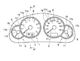
図1に示すように、本発明の第1の実施の形態に係わる車両用計器は、車両が備えるエンジンの回転数を指示するエンジン回転計1と、車両の速度を指示する速度計2と、エンジンの冷却水の温度を指示する水温計3と、車両が備える燃料タンクに入っている燃料残量を指示する燃料計4と、その他の各種情報を運転者に対して表示する表示器5とを有する。通常、図1に示す車両用計器は、車両の車室内に設けたインストルメントパネルに配設されている。エンジン回転計1、速度計2、水温計3及び燃料計4は、それぞれ、文字板8と、文字板8上に円状に配置された目盛り17a及び文字や記号(以後、「文字17b」と略す)と、当該円の中心を回る指針11と、文字板8の外周に円状に配置された意匠発光部16とを有するアナログ指示計器である。表示器5は意匠発光部16の内側に配置されている
エンジン回転計1の指針11は、エンジンのカム軸から直接検出されたエンジンの回転数に応じて回動する。速度計2の指針11は、車速センサなどにより検出された車両の速度に応じて回動する。水温計3の指針11は、エンジンの冷却水の温度に応じて回動する。燃料計4の指針11は、燃料タンクに入っている燃料残量に応じて回動する。表示器5には、例えば、プッシュスイッチ式のエンジンスタートシステムにおけるエンジンの始動方法の操作ガイダンスを表示したり、車両が備える自動変速機の変速位置を表示したり、車両の走行距離を表示したりする液晶表示装置(LCD)や、オートクルーズ機能動作状態などの車両運転状態を表示するインジケータや、車両の半ドア警告などの警告ランプなどが含まれる。意匠発光部16は、発光することにより車両に乗車した運転者に意匠として認識される。
(First embodiment)
As shown in FIG. 1, the vehicle meter according to the first embodiment of the present invention includes an
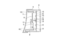
図2は、図1のA−A’切断面に沿った車両用計器のうちエンジン回転計1部分の断面を示す。エンジン回転計1は、リアカバー6及びフロントカバー7からなるハウジング内に配置されている。具体的には、車両用計器は、ハウジング内に、リアカバー6に固定された基板10と、基板10よりもフロントカバー7側に平行に配置された円状の文字板8と、文字板8を貫通する回転軸により基板10に固定され、文字板8の上に配置された指針11と、文字板8の開口部分に嵌め込まれた表示器5と、文字板8の外周に沿って円筒状の配置された拡散板9と、基板10上に指針11の回転軸に対して同心円状に配置された意匠発光部用光源12、文字板用光源13及び指針用光源14とを備える。
FIG. 2 shows a cross section of the
指針11は、文字板8上を回動する。意匠発光部用光源12の発光により、意匠発光部用光源12の光は直上の拡散板9の裏面を照射し、拡散板9内部を透過した光は透明のフロントカバー7を透過してリング状の発光する図1の意匠発光部16として運転者に認識される。以後、リング状の発光する意匠発光部16の一例として、「リング照明部16」について説明を続ける。文字板用光源13の発光により、文字板8上の目盛り17a及び文字17bが照明され、指針用光源14の発光により、指針11が照明される。なお、リング照明部16、目盛り17a、文字17b及び指針11の総てが照明されている状態を「通常照明状態」と呼ぶ。
The
なおここでは、車両用計器のうちエンジン回転計1部分について図示及び説明を行ったが、速度計2、水温計3及び燃料計4についても同様な構成を有する。
Here, although the
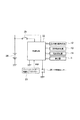
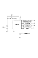
図3に示すように、図1に示した車両用計器の制御システムは、意匠発光部用光源12、文字板用光源13、指針用光源14及び表示器5に接続された制御回路22と、運転者が車両に乗車したことを検知する乗車検知センサーとを少なくとも有する。制御回路22は、乗車検知センサーが運転者の車両への乗車を検知した時にリング照明部16を発光させる。
As shown in FIG. 3, the control system for the vehicle instrument shown in FIG. 1 includes a
第1の実施の形態では、「乗車検知センサー」の一例として、制御回路22と通信することができるインテリジェントキー制御コントローラー23について説明する。インテリジェントキー制御コントローラー23は、運転者が携帯するインテリジェントキーが車両の室内に在ることを検知し、制御回路22へ通信する。こうして、運転者が車両に乗車したことが検知され、制御回路22に送信される。
In the first embodiment, an intelligent
車両用計器の制御システムは、制御回路22に接続されたドア開閉センサー24を更に有することが望ましい。ドア開閉センサー24は、ドアが開いている状態であるか閉じている状態であるかを検知し、開いた状態から閉じる動作を行った時や閉じた状態から開く動作を行った時を検知する。この場合、制御回路22は、ドア開閉センサー24及びインテリジェントキー制御コントローラー23からの信号を受けて、意匠発光部用光源12、文字板用光源13、指針用光源14の発光及び表示器5の表示を制御する。
The vehicle instrument control system preferably further includes a door opening / closing sensor 24 connected to the
なお、キースイッチ25がオンされると、車両が備えるバッテリ26から制御回路22を介して、意匠発光部用光源12、文字板用光源13、指針用光源14及び表示器5、インテリジェントキー制御コントローラー23、ドア開閉センサー24へ電力が供給される。
When the
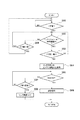
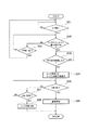
図4を参照して、図3に示した車両用計器の制御システムの動作手順を説明する。制御回路22は、キースイッチ25がオンされていなくてもバッテリ26により以下に示す動作を常時開始する。
With reference to FIG. 4, the operation procedure of the control system for the vehicle instrument shown in FIG. 3 will be described. The
(イ)先ずS01段階において、ドア開閉センサー24は車両のドアが開くことを監視している。即ち、車両のドアが閉じていれば(S01段階においてNO)、S01段階を繰り返し行い(監視し続ける)、車両のドアが開いていれば(S01段階においてYES)、S02段階に進む。 (A) First, in step S01, the door opening / closing sensor 24 monitors the opening of the vehicle door. That is, if the vehicle door is closed (NO in step S01), step S01 is repeated (continue monitoring), and if the vehicle door is open (YES in step S01), the process proceeds to step S02.
(ロ)S02段階において、インテリジェントキー制御コントローラー23はインテリジェントキーが車両の室内に在るか否かを判断する。インテリジェントキーが車両の室内に在る場合(S02段階においてYES)、S03段階に進み、インテリジェントキーが車両の室内に無い場合(S02段階においてNO)、S09段階に進む。S09段階において、ドア開閉センサー24は車両のドアが開いた状態から閉じる動作が行われたか否かを判断する。ドアが開いた状態から閉じる動作が行われた場合(S09段階においてYES)、S01段階に戻り、ドアが開いた状態から閉じる動作が行われない場合、即ちドアが開いたままの場合(S09段階においてNO)、S02段階に戻る。
(B) In step S02, the intelligent
(ハ)S03段階において、ドア開閉センサー24は車両のドアが開いた状態から閉じる動作が行われたか否かを判断する。ドアが開いた状態から閉じる動作が行われた場合(S03段階においてYES)、S04段階に進み、ドアが開いた状態から閉じる動作が行われない場合(S03段階においてNO)、S02段階に戻る。 (C) In step S03, the door opening / closing sensor 24 determines whether or not an operation of closing the vehicle door from the opened state has been performed. If the closing operation is performed from the opened state (YES in step S03), the process proceeds to step S04. If the closing operation is not performed from the opened state (NO in step S03), the process returns to step S02.
(ニ)S04段階において、意匠発光部用光源12が発光して、リング照明部16が照明される。またこれと同時に、表示器5には、エンジンの始動方法の操作ガイダンスが表示される。その後、S05段階に進む。なおこの時、リング照明部16のみが照明され、目盛り17a、文字17b及び指針11は照明されない。また、この時のリング照明部16の照明照度は、「通常照明状態」の時のリング照明部16の照明照度とは異なり、昼間/夜間において乗車時の照明として適切な照度で照明する。
(D) In step S04, the
(ホ)S05段階において、制御回路22はイグニッションスイッチ(キースイッチ)25がオンされているか否かを判断する。イグニッションスイッチ25がオンされている場合(S05段階においてYES)、S06段階に進み、イグニッションスイッチ25がオンされていない、すなわちオフ状態である場合(S05段階においてNO)、S07段階に進む。
(E) In step S05, the
(へ)S06段階において、意匠発光部用光源12、文字板用光源13及び指針用光源14の総てが発光して、リング照明部16、目盛り17a、文字17b及び指針11の総てが照明されて、「通常照明状態」が形成される。一方、S07段階において、制御回路22は15秒経過したか否かを判断する。15秒経過していない場合(S07段階においてNO)、S05段階に戻る。15秒経過した場合(S07段階においてYES)、S08段階に進み、リング照明部16の照明をオフする。
(F) In step S06, the
このように、図4のフローチャートが示す動作により、運転者が車両に乗り込んだ(S02においてYES)後、ドアを閉める(S03段階においてYES)と、リング照明部16のみが照明され、エンジンの始動方法の操作ガイダンスが表示される(S04)。その後、運転者がキースイッチ25をオンする(S05段階においてYES)と、車両用計器は「通常照明状態」となる(S06)。また、乗員がドアを開いた後に忘れ物に気づき取りに行く場合、或いは荷室に物を入れる場合のように、ドアを開いた(S01段階においてYES)後に乗員が室内に乗り込まない場合(S02段階においてNO)にはリング照明部16の照明及びエンジン始動方法の操作ガイダンスの表示を行わない。
As described above, when the driver enters the vehicle (YES in S02) and then closes the door (YES in S03), only the
以上説明したように、本発明の第1の実施の形態によれば、運転者が車両に乗り込みドアを閉じるとリング照明部16が適切な照度にて照明され、同時にエンジン始動方法の操作ガイダンスが表示されるため、極めて斬新な印象を与える車両用計器を提供することができる。
As described above, according to the first embodiment of the present invention, when the driver enters the vehicle and closes the door, the
また、図1に示したように、表示器5はリング照明部16の内側に配置されているため、リング照明部16を照明することにより運転者を車両用計器に注目させ、表示器5に表示されたエンジン始動方法の操作ガイダンスに注目させることができる。
Further, as shown in FIG. 1, since the
更に、ドアを開いた後に乗員が室内に乗り込まない場合にはリング照明部16の照明及びエンジン始動方法の操作ガイダンスの表示を行わず、乗員が室内に乗り込んだ時のみリング照明部16の照明及びエンジン始動方法の操作ガイダンスの表示を行うため、無駄な電力の消費を抑えることができる。
Further, when the occupant does not enter the room after opening the door, the illumination of the
更に、運転者が車両に乗り込んだ後、ドアを閉しめた時にリング照明部16を照明させることにより、運転者はリング照明部16が発光する瞬間を見ることができ、より斬新な印象を与えることもできる。
Furthermore, after the driver gets into the vehicle, when the door is closed, the
(第2の実施の形態)
本発明の第2の実施の形態では、「乗車検知センサー」の他の例として、運転者が運転席シートに着座したことを検知する着座センサー27について図5を参照して説明する。即ち、第2の実施の形態では、図3のインテリジェントキー制御コントローラー23の替わりに、図5に示すように着座センサー27を用いる。
(Second Embodiment)
In the second embodiment of the present invention, as another example of the “boarding detection sensor”, a seating sensor 27 that detects that the driver is seated on the driver's seat will be described with reference to FIG. 5. That is, in the second embodiment, a seating sensor 27 is used as shown in FIG. 5 instead of the intelligent
着座センサー27は、車両の運転席シートに設置され、運転者が運転席シートに着座したことを検知して、制御回路22へ送信する。制御回路22は、運転者が運転席シートに着座した時に意匠発光部16を発光させる。なお、第2の実施の形態に係わる車両用計器の制御システムは、ドア開閉センサーを有さない。
The seating sensor 27 is installed in the driver's seat of the vehicle, detects that the driver is seated on the driver's seat, and transmits it to the
その他の構成は、図3と同じであるため、説明を省略する。また、車両用計器の正面図及び断面図の構成も、図1及び図2と同じであるため、図示及び説明を省略する。 Other configurations are the same as those in FIG. Moreover, since the structure of the front view of a vehicle meter and sectional drawing is also the same as FIG.1 and FIG.2, illustration and description are abbreviate | omitted.
以上説明したように、第2の実施の形態によれば、第1の実施の形態と同様な作用効果が得られるだけでなく、運転者が運転席シートに着座した時にリング照明部16を発光させることにより、運転者はリング照明部16が発光する瞬間を見ることができ、より斬新な印象を与えることもできる。
As described above, according to the second embodiment, not only the same effect as the first embodiment can be obtained, but also the
(第3の実施の形態)
本発明の第3の実施の形態では、制御回路22が、乗車検知センサーが運転者の車両への乗車を検知した時から所定時間が経過した後に、リング照明部16を発光させる場合について説明する。なお、第3の実施の形態に係わる車両用計器の正面図及び断面図、及びシステム構成は、図1乃至図3と同じであり図示及び説明を省略する。
(Third embodiment)
In the third embodiment of the present invention, a case will be described in which the
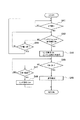
図6に示しように、第3の実施の形態では、インテリジェントキー制御コントローラー23がインテリジェントキーが車両の室内に在ると判断した時(S22段階においてYES)から、所定時間が経過するまで待つ(S23段階)。そして、所定時間が経過した(S23段階においてYES)後に、S24段階において意匠発光部用光源12が発光してリング照明部16が照明され、同時に、表示器5にはエンジンの始動方法の操作ガイダンスが表示される。
As shown in FIG. 6, in the third embodiment, the intelligent
その他の段階、即ち、図6のS21、S22、S24〜S29段階は、それぞれ図4のS01、S02、S04〜S09段階と同じであり、説明を省略する。 The other steps, that is, steps S21, S22, and S24 to S29 in FIG. 6 are the same as steps S01, S02, and S04 to S09 in FIG.
以上説明したように、第3の実施の形態によれば、第1の実施の形態と同様な作用効果が得られるだけでなく、運転者が車両に乗り込んだ時から所定時間が経過した後に、リング照明部16を発光させることにより、運転者はリング照明部16が発光する瞬間を見ることができ、より斬新な印象を与えることもできる。
As described above, according to the third embodiment, not only the same effects as the first embodiment can be obtained, but also after a predetermined time has elapsed since the driver got into the vehicle, By causing the
(第4の実施の形態)
本発明の第4の実施の形態では、制御回路22が、乗車検知センサーが運転者の車両への乗車を検知した後に、意匠発光部16を発光させる場合について説明する。即ち、運転者の車両への乗車を検知した後、ドアの開閉状態を判断せず、また所定時間の経過を待たずに、リング照明部16を発光させる。なお、第4の実施の形態に係わる車両用計器の正面図及び断面図、及びシステム構成は、図1乃至図3と同じであり図示及び説明を省略する。
(Fourth embodiment)
In the fourth embodiment of the present invention, a case will be described where the
図7に示しように、第4の実施の形態では、インテリジェントキーが車両の室内に在るとインテリジェントキー制御コントローラー23が判断した(S42段階においてYES)後、S44段階において意匠発光部用光源12が発光してリング照明部16が照明され、同時に、表示器5にはエンジンの始動方法の操作ガイダンスが表示される。
As shown in FIG. 7, in the fourth embodiment, after the intelligent
その他の段階、即ち、図7のS41、S42、S44〜S49段階は、それぞれ図4のS01、S02、S04〜S09段階と同じであり、説明を省略する。 The other steps, that is, steps S41, S42, and S44 to S49 in FIG. 7 are the same as steps S01, S02, and S04 to S09 in FIG.
以上説明したように、第4の実施の形態によれば、第1の実施の形態と同様な作用効果が得られる。 As described above, according to the fourth embodiment, the same operational effects as those of the first embodiment can be obtained.
(その他の実施の形態)
上記のように、本発明は、第1乃至第4の実施の形態によって記載したが、この開示の一部をなす論述及び図面はこの発明を限定するものであると理解すべきではない。この開示から当業者には様々な代替実施の形態、実施例及び運用技術が明らかとなろう。
(Other embodiments)
As described above, the present invention has been described according to the first to fourth embodiments. However, it should not be understood that the description and drawings constituting a part of this disclosure limit the present invention. From this disclosure, various alternative embodiments, examples and operational techniques will be apparent to those skilled in the art.
たとえば、第1乃至第4の実施の形態では、運転者が車両に乗車したことを検知した時に、リング照明部16のみを照明していたが、本発明はこれに限定されるものではない。この時に、文字板用光源13及び指針用光源14をも発光させて、リング照明部16のみならず、目盛り17a、文字17b等をも照明させて、意匠として運転者に認識させても構わない。
For example, in the first to fourth embodiments, only the
このように、本発明はここでは記載していない様々な実施の形態等を包含するということを理解すべきである。したがって、本発明はこの開示から妥当な特許請求の範囲に係る発明特定事項によってのみ限定されるものである。 Thus, it should be understood that the present invention includes various embodiments and the like not described herein. Therefore, the present invention is limited only by the invention specifying matters according to the scope of claims reasonable from this disclosure.
1…エンジン回転計
2…速度計
3…水温計
4…燃料計
5…表示器
6…リアカバー
7…フロントカバー
8…文字板
9…拡散板
10…基板
11…指針
12…意匠発光部用光源
13…文字板用光源
14…指針用光源
16…意匠発光部(リング照明部)
17a…目盛り
17b…文字
22…制御回路
23…インテリジェントキー制御コントローラー
24…ドア開閉センサー
25…キースイッチ
26…バッテリ
27…着座センサー
DESCRIPTION OF
17a ...
Claims (7)
前記車両に乗車した前記運転者に、発光することにより意匠として認識される意匠発光部と、
前記乗車検知センサーが前記運転者の前記車両への乗車を検知した時に、前記意匠発光部を発光させる制御回路
とを有することを特徴とする車両用計器。 A boarding detection sensor for detecting that a vehicle driver has boarded the vehicle;
A design light emitting unit that is recognized as a design by emitting light to the driver who has boarded the vehicle;
And a control circuit that causes the design light emitting section to emit light when the boarding detection sensor detects that the driver has boarded the vehicle.
前記制御回路は、前記乗車検知センサーが前記運転者の前記車両への乗車を検知した後に、前記ドア開閉センサーが前記ドアが開いた状態から閉じた状態になったことを検知した時に、前記意匠発光部を発光させることを特徴とする請求項1乃至3何れか1項記載の車両用計器。 A door opening / closing sensor for detecting that the vehicle door is in a closed state from an open state;
The control circuit, when the boarding sensor detects that the driver has entered the vehicle, and then the door opening / closing sensor detects that the door has changed from an open state to a closed state. The vehicular instrument according to any one of claims 1 to 3, wherein the light emitting section is caused to emit light.
前記制御回路は、前記意匠発光部を発光させると同時に、前記表示器に前記エンジンの始動方法を表示することを特徴とする請求項1乃至6何れか1項記載の車両用計器。 The driver who has boarded the vehicle further has a display for displaying a starting method of an engine provided in the vehicle,
The vehicle control instrument according to any one of claims 1 to 6, wherein the control circuit causes the design light-emitting unit to emit light and simultaneously displays the engine starting method on the display.
Priority Applications (1)
| Application Number | Priority Date | Filing Date | Title |
|---|---|---|---|
| JP2004120571A JP2005297910A (en) | 2004-04-15 | 2004-04-15 | Vehicle instrument |
Applications Claiming Priority (1)
| Application Number | Priority Date | Filing Date | Title |
|---|---|---|---|
| JP2004120571A JP2005297910A (en) | 2004-04-15 | 2004-04-15 | Vehicle instrument |
Publications (1)
| Publication Number | Publication Date |
|---|---|
| JP2005297910A true JP2005297910A (en) | 2005-10-27 |
Family
ID=35329963
Family Applications (1)
| Application Number | Title | Priority Date | Filing Date |
|---|---|---|---|
| JP2004120571A Pending JP2005297910A (en) | 2004-04-15 | 2004-04-15 | Vehicle instrument |
Country Status (1)
| Country | Link |
|---|---|
| JP (1) | JP2005297910A (en) |
Cited By (3)
| Publication number | Priority date | Publication date | Assignee | Title |
|---|---|---|---|---|
| WO2007108334A1 (en) * | 2006-03-16 | 2007-09-27 | Pioneer Corporation | Start control device, start control method, start control program and computer readable recording medium |
| JP2011105163A (en) * | 2009-11-18 | 2011-06-02 | Faltec Co Ltd | Lighting system for vehicle |
| JP2014149157A (en) * | 2013-01-31 | 2014-08-21 | Mazda Motor Corp | Vehicle meter device |
-
2004
- 2004-04-15 JP JP2004120571A patent/JP2005297910A/en active Pending
Cited By (3)
| Publication number | Priority date | Publication date | Assignee | Title |
|---|---|---|---|---|
| WO2007108334A1 (en) * | 2006-03-16 | 2007-09-27 | Pioneer Corporation | Start control device, start control method, start control program and computer readable recording medium |
| JP2011105163A (en) * | 2009-11-18 | 2011-06-02 | Faltec Co Ltd | Lighting system for vehicle |
| JP2014149157A (en) * | 2013-01-31 | 2014-08-21 | Mazda Motor Corp | Vehicle meter device |
Similar Documents
| Publication | Publication Date | Title |
|---|---|---|
| US7847680B2 (en) | Motor vehicle gear selector with integrated display | |
| US6975217B2 (en) | Vehicle fuel mileage meter | |
| JP4440145B2 (en) | Indicator for hybrid electric vehicle | |
| US9744903B2 (en) | Urgent vehicle warning indicator using vehicle illumination | |
| US20060181399A1 (en) | Display device for vehicle | |
| US20180336329A1 (en) | Vehicle Steering Assembly | |
| JP2008168786A (en) | In-vehicle device operation guidance device | |
| KR20000077430A (en) | Meter for vehicle | |
| JP2018122739A (en) | In-vehicle device | |
| JP2003312314A (en) | Vehicle meter device | |
| CN204077387U (en) | Display system for displaying information and vehicle including same | |
| JP2014149157A (en) | Vehicle meter device | |
| JP5489694B2 (en) | Vehicle display device | |
| JP6310826B2 (en) | In-vehicle display device and instrument panel | |
| JP4473542B2 (en) | Vehicle display device | |
| JP4055394B2 (en) | Vehicle display device | |
| JP2008308066A (en) | Washer liquid remaining amount warning device | |
| JP5277568B2 (en) | Vehicle display device | |
| JP2024099499A (en) | System and program and the like | |
| JP2009244033A (en) | Meter display system for vehicle | |
| JP3889908B2 (en) | Warning display device for vehicles | |
| JP6439959B2 (en) | Vehicle display device | |
| JP4175321B2 (en) | Pointer instrument | |
| JP2008007011A (en) | Display device for vehicle | |
| JP4322872B2 (en) | Vehicle meter system |
Legal Events
| Date | Code | Title | Description |
|---|---|---|---|
| A621 | Written request for application examination |
Free format text: JAPANESE INTERMEDIATE CODE: A621 Effective date: 20070402 |
|
| A977 | Report on retrieval |
Free format text: JAPANESE INTERMEDIATE CODE: A971007 Effective date: 20081217 |
|
| A131 | Notification of reasons for refusal |
Free format text: JAPANESE INTERMEDIATE CODE: A131 Effective date: 20090113 |
|
| A02 | Decision of refusal |
Free format text: JAPANESE INTERMEDIATE CODE: A02 Effective date: 20090602 |