JP2005297895A - Vehicle door structure - Google Patents
Vehicle door structure Download PDFInfo
- Publication number
- JP2005297895A JP2005297895A JP2004120238A JP2004120238A JP2005297895A JP 2005297895 A JP2005297895 A JP 2005297895A JP 2004120238 A JP2004120238 A JP 2004120238A JP 2004120238 A JP2004120238 A JP 2004120238A JP 2005297895 A JP2005297895 A JP 2005297895A
- Authority
- JP
- Japan
- Prior art keywords
- door
- reinforcement
- width direction
- joint
- beltline
- Prior art date
- Legal status (The legal status is an assumption and is not a legal conclusion. Google has not performed a legal analysis and makes no representation as to the accuracy of the status listed.)
- Pending
Links
Images
Landscapes
- Body Structure For Vehicles (AREA)
Abstract
【課題】 リインフォースメントとドアパネルとの結合剛性及び結合強度を向上する。
【解決手段】 ベルトラインインナリインフォースメント20がフロントサイドドア10のベルトラインに沿って配設されており、ベルトラインインナリインフォースメント20の前部20Aと、フロントサイドドア10の前部10Dとなるヒンジサイドパネル30との結合部が、ドア前後方向及びドア幅方向にオフセットした2箇所の結合部P1、P2で固定されている。
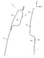
【選択図】 図1PROBLEM TO BE SOLVED: To improve the joint rigidity and joint strength between a reinforcement and a door panel.
A beltline inner reinforcement 20 is disposed along a beltline of a front side door 10, and a hinge that becomes a front portion 20A of the beltline inner reinforcement 20 and a front portion 10D of the front side door 10. The connecting portion with the side panel 30 is fixed by two connecting portions P1 and P2 that are offset in the door front-rear direction and the door width direction.
[Selection] Figure 1
Description
本発明は車両用ドア構造に関し、特に、自動車等の車体に適用される車両用ドア構造に関する。 The present invention relates to a vehicle door structure, and more particularly to a vehicle door structure applied to a vehicle body such as an automobile.
従来から、自動車等の車体に適用される車両用ドア構造においては、車体に形成されたドア開口にドア開口を開閉するドアを配設し、該ドアのドア本体内にベルトラインに沿ってリインフォースメントを配設した構成が知られている(例えば、特許文献1参照)。
しかしながら、特許文献1のような車両用ドア構造では、リインフォースメントの後端部に車両後側に屈曲する平板状のフランジ部が形成されており、このフランジ部がドアロックリインホースの延長部の後フランジ部とともにドアインナパネルの後縦壁部にスポット溶接により結合されている。即ち、平面視直線状のフランジ部によってリインフォースメントがドアパネルに固定されている。この結果、リインフォースメントに車幅方向から作用する荷重、車体前後方向から作用する荷重、及び捩れ荷重に対して、リインフォースメントとドアパネルとの結合剛性及び結合強度が低い。 However, in the vehicle door structure as disclosed in Patent Document 1, a flat flange portion that is bent toward the vehicle rear side is formed at the rear end portion of the reinforcement, and this flange portion is an extension portion of the door lock rein hose. It is joined to the rear vertical wall portion of the door inner panel together with the rear flange portion by spot welding. That is, the reinforcement is fixed to the door panel by a flange portion that is linear in a plan view. As a result, the reinforcement rigidity and the bond strength between the reinforcement and the door panel are low with respect to the load acting on the reinforcement from the vehicle width direction, the load acting from the vehicle longitudinal direction, and the torsional load.
本発明は上記事実を考慮し、リインフォースメントとドアパネルとの結合剛性及び結合強度を向上できる車両用ドア構造を提供することが目的である。 In view of the above fact, an object of the present invention is to provide a vehicle door structure capable of improving the rigidity and strength of the reinforcement and the door panel.
請求項1記載の本発明の車両用ドア構造は、ドアの前後方向に沿って配設され、前部がドアの前部に固定され後部がドアの後部に固定されたリインフォースメントを有し、
前記リインフォースメントの前部と前記ドアの前部との前側結合部と、前記リインフォースメントの後部と前記ドアの後部との後側結合部と、の少なくとも一方が、前記ドアの前後方向及び前記ドアの幅方向にオフセットした2箇所以上で固定されていることを特徴とする。
The door structure for a vehicle according to the first aspect of the present invention has a reinforcement disposed along the front-rear direction of the door, the front portion being fixed to the front portion of the door and the rear portion being fixed to the rear portion of the door,
At least one of a front coupling portion between the front portion of the reinforcement and the front portion of the door, and a rear coupling portion between the rear portion of the reinforcement and the rear portion of the door, the front-rear direction of the door and the door It is characterized by being fixed at two or more locations offset in the width direction.
従って、ドアの前後方向に沿って配設され、前部がドアの前部に固定され後部がドアの後部に固定されたリインフォースメントの前部とドアの前部との前側結合部と、リインフォースメントの後部とドアの後部との後側結合部と、の少なくとも一方が、ドアの前後方向及びドアの幅方向にオフセットした2箇所以上で固定されている。この結果、リインフォースメントに車幅方向から作用する荷重、車体前後方向から作用する荷重、及び捩れ荷重を、前側結合部と後側結合部との少なくとも一方において、ドアの前後方向及びドアの幅方向にオフセットした2箇所以上で受けることができる。このため、リインフォースメントとドアパネルとの結合剛性及び結合強度を向上できる。 Accordingly, a front joint portion between the front portion of the reinforcement and the front portion of the door which is disposed along the front-rear direction of the door, the front portion is fixed to the front portion of the door and the rear portion is fixed to the rear portion of the door, At least one of the rear part of the ment and the rear joint part of the rear part of the door is fixed at two or more positions offset in the front-rear direction of the door and the width direction of the door. As a result, the load acting on the reinforcement from the vehicle width direction, the load acting from the vehicle body front-rear direction, and the torsion load are applied to at least one of the front coupling portion and the rear coupling portion in the front-rear direction of the door and the width direction of the door. It can be received at two or more locations offset by. For this reason, the joint rigidity and the joint strength between the reinforcement and the door panel can be improved.
請求項2記載の本発明は、請求項1に記載の車両用ドア構造において、前記リインフォースメントが閉断面構造であることを特徴とする。 According to a second aspect of the present invention, in the vehicle door structure according to the first aspect, the reinforcement has a closed cross-sectional structure.
従って、請求項1に記載の内容に加えて、リインフォースメントが閉断面構造であるため、リインフォースメントの剛性及び強度が向上すると共に結合剛性及び結合強度も向上する。この結果、ドアフレームの剛性及び強度が向上する。 Therefore, in addition to the content described in claim 1, since the reinforcement has a closed cross-sectional structure, the rigidity and strength of the reinforcement are improved, and the joint rigidity and the joint strength are also improved. As a result, the rigidity and strength of the door frame are improved.
請求項1記載の本発明の車両用ドア構造は、ドアの前後方向に沿って配設され、前部がドアの前部に固定され後部がドアの後部に固定されたリインフォースメントを有し、リインフォースメントの前部とドアの前部との前側結合部と、リインフォースメントの後部とドアの後部との後側結合部と、の少なくとも一方が、ドアの前後方向及びドアの幅方向にオフセットした2箇所以上で固定されているため、リインフォースメントとドアパネルとの結合剛性及び結合強度を向上できるという優れた効果を有する。 The door structure for a vehicle according to the first aspect of the present invention includes a reinforcement that is disposed along the front-rear direction of the door, the front portion is fixed to the front portion of the door, and the rear portion is fixed to the rear portion of the door, At least one of the front coupling portion between the front portion of the reinforcement and the front portion of the door and the rear coupling portion of the rear portion of the reinforcement and the rear portion of the door is offset in the front-rear direction of the door and the width direction of the door. Since it is fixed at two or more locations, it has an excellent effect that the rigidity and strength of the reinforcement and the door panel can be improved.
請求項2記載の本発明は、請求項1に記載の車両用ドア構造において、リインフォースメントが閉断面構造であるため、請求項1に記載の効果に加えて、ドアフレームの剛性及び強度が向上するという優れた効果を有する。 According to a second aspect of the present invention, in the vehicle door structure according to the first aspect, since the reinforcement has a closed cross-sectional structure, the rigidity and strength of the door frame are improved in addition to the effect of the first aspect. It has an excellent effect.
本発明における車両用ドア構造の第1実施形態を図1〜図3に従って説明する。 1st Embodiment of the vehicle door structure in this invention is described according to FIGS.
なお、図中矢印FRはドア前方方向を、矢印UPはドア上方方向を、矢印INはドア幅内側方向を示す。 In the figure, the arrow FR indicates the door forward direction, the arrow UP indicates the door upward direction, and the arrow IN indicates the door width inner direction.
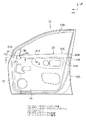
図3に示される如く、本実施形態のフロントサイドドア10は、ドアアウタパネル12とドアインナパネル14とを結合した最中状のドア本体10Aとウインドフレーム10Bとを一体形成したプレスドア構造となっており、ドア本体10A内にはウインドフレーム10Bのウインド開口を開閉するドアガラスが昇降可能に配設されている。
As shown in FIG. 3, the
ドア本体10A内にはフロントサイドドア10のベルトライン10Cに沿ってリインフォースメントとしてのベルトラインインナリインフォースメント20が前後方向に配設されている。また、ベルトラインインナリインホース20の前部20Aはフロントサイドドア10の前部10Dに固定されており、ベルトラインインナリインホース20の後部20Bはフロントサイドドア10の後部10Eに固定されている。
In the door
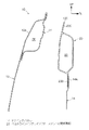
図2に示される如く、ベルトラインインナリインフォースメント20は、ドア上下方向を長手方向とする略矩形の閉断面部22を有する閉断面構造となっており、閉断面部22の上部には、ドア上方に延設された上フランジ20Cが形成されている。また、ベルトラインインナリインフォースメント20における閉断面部22の下部には、ドア下方に延設された下フランジ20Dが形成されており、下フランジ20Dのドア幅方向内側面には、ドアインナパネル14の上端縁部14Aが溶接等によって結合されている。
As shown in FIG. 2, the beltline
一方、ドアアウタパネル12の上部12Aのドア幅方向内側には、ドアアウタリインフォースメント24がドア前後方向に沿って配設されており、ドアアウタパネル12の上部12Aとドアアウタリインフォースメント24とによってドア前後方向に伸びる閉断面部26が形成されている。
On the other hand, a door
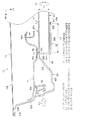
図1に示される如く、ドアアウタパネル12の前部12Bのドア幅方向内側には、ドアインナパネル14の前部を構成するヒンジサイドパネル30がドア上下方向に沿って配設されており、ヒンジサイドパネル30の前壁部30Aのドア幅方向内側端部には、ドア前方へ向ってフランジ30Bが形成されている。また、ヒンジサイドパネル30のフランジ30Bには、ドアアウタパネル12の前端縁部12Cがヘミング加工によって結合されている。
As shown in FIG. 1, a
ヒンジサイドパネル30の前壁部30Aのドア幅方向外側端部からは、ドア後方へ向って側壁部30Cが形成されており、ヒンジサイドパネル30には側壁部30Cのドア後方側には所定の間隔を開けて平面視L字状の結合部32が形成されている。
From the door width direction outer side edge part of the
ヒンジサイドパネル30における結合部32の前壁部32Aのドア幅方向外側端部と、側壁部30Cの後端部は、ドア幅方向内側前方からドア幅方向外側後方へ伸びる傾斜壁部32Dによって連結されており、傾斜壁部32Dと結合部32の前壁部32Aとの間には、ドア前後方向に伸びる補強用のリブ34が形成されている。また、結合部32の側壁部32Bは、前壁部32Aのドア幅方向内側端部からドア後方へ向って延設されている。
The door width direction outer end of the
ベルトラインインナリインホース20の前端20Cは、結合部32の前壁部32Aに達しており、ベルトラインインナリインホース20の前端20Cは、結合部32の前壁部32Aのドア幅方向外側端部32Cと結合部P1において溶接により結合されている。
The
また、結合部32の側壁部32Bの後端部32Dは、ベルトラインインナリインフォースメント20のドア幅方向内側壁部20Eと結合部P2において溶接により結合されている。
Further, the rear end portion 32D of the side wall portion 32B of the
この結果、ベルトラインインナリインホース20と、ヒンジサイドパネル30の結合部32との結合部P1と結合部P2は、ドア前後方向に距離L1オフセットしており、ドア幅方向に距離L2オフセットしている。
As a result, the connecting part P1 and the connecting part P2 between the beltline
従って、ベルトラインインナリインフォースメント20にドア幅方向(図1ではドア幅方向外側)から作用する荷重F1を、ドア前後方向及びドア幅方向にオフセットした2箇所の結合部P1、P2で受けることができるため、ベルトラインインナリインフォースメント20に車幅方向から作用する荷重F1に対するベルトラインインナリインフォースメント20とヒンジサイドパネル30との結合剛性及び結合強度を向上できるようになっている。また、ベルトラインインナリインフォースメント20にドア前後方向(図1ではドア前方)から作用する荷重F2を、ドア前後方向及びドア幅方向にオフセットした2箇所の結合部P1、P2で受けることができるため、ベルトラインインナリインフォースメント20に車体前後方向から作用する荷重F2に対するベルトラインインナリインフォースメント20とヒンジサイドパネル30との結合剛性及び結合強度を向上できるようになっている。また、ベルトラインインナリインフォースメント20に作用する捩れ荷重F3を、ドア前後方向及びドア幅方向にオフセットした2箇所の結合部P1、P2で受けることができるため、ドアの捩れ荷重F3に対するベルトラインインナリインフォースメント20とヒンジサイドパネル30との結合剛性及び結合強度を向上できるようになっている。
Accordingly, the load F1 acting on the beltline
図1に示される如く、ドアアウタパネル12の前部12Bとヒンジサイドパネル30との間には、アウタリインフォースメントフロント40がドア上下方向に沿って配設されており、アウタリインフォースメントフロント40の前部40Aは、ドアフレーム42に溶接等によって結合されている。また、アウタリインフォースメントフロント40の後部40Bには、ガラスランチャンネル44が溶接等によって結合されており、アウタリインフォースメントフロント40の前後方向中間部40Cには、結合部P1を溶接するための作業孔46が形成されている。
As shown in FIG. 1, an
次に、本実施形態の作用を説明する。 Next, the operation of this embodiment will be described.
本実施形態では、フロントサイドドア10のベルトライン10Cに沿って配設され、前部20Aがフロントサイドドア10の前部10Dに固定され、後部20Bがフロントサイドドア10の後部10Eに固定されたベルトラインインナリインフォースメント20の前部20Aと、フロントサイドドア10の前部10Dとなるヒンジサイドパネル30との前側結合部が、ドア前後方向及びドア幅方向にオフセットした2箇所の結合部P1、P2で固定されている。
In the present embodiment, the
この結果、ベルトラインインナリインフォースメント20にドア幅方向(図1ではドア幅方向外側)から作用する荷重F1を、ドア前後方向及びドア幅方向にオフセットした2箇所の結合部P1、P2で受けることができる。このため、ベルトラインインナリインフォースメント20に車幅方向から作用する荷重F1に対するベルトラインインナリインフォースメント20とヒンジサイドパネル30との結合剛性及び結合強度を向上できる。
As a result, the load F1 acting on the beltline
また、ベルトラインインナリインフォースメント20にドア前後方向(図1ではドア前方)から作用する荷重F2を、ドア前後方向及びドア幅方向にオフセットした2箇所の結合部P1、P2で受けることができる。このため、ベルトラインインナリインフォースメント20に車体前後方向から作用する荷重F2に対するベルトラインインナリインフォースメント20とヒンジサイドパネル30との結合剛性及び結合強度を向上できる。
Further, the load F2 acting on the beltline
また、ベルトラインインナリインフォースメント20に作用する捩れ荷重F3を、ドア前後方向及びドア幅方向にオフセットした2箇所の結合部P1、P2で受けることができる。このため、捩れ荷重F3に対するベルトラインインナリインフォースメント20とヒンジサイドパネル30との結合剛性及び結合強度を向上できる。
Further, the torsional load F3 acting on the beltline
従って、本実施形態では、ベルトラインインナリインフォースメント20とヒンジサイドパネル30との結合剛性及び結合強度を向上できる。
Therefore, in this embodiment, the joint rigidity and the joint strength between the beltline
また、本実施形態では、ベルトラインインナリインフォースメント20が閉断面部22を有する閉断面構造であるため、ベルトラインインナリインフォースメント20の剛性及び強度が向上すると共に結合剛性及び結合強度も向上する。この結果、フロントサイドドア10のドアフレームの剛性及び強度が向上する。
Moreover, in this embodiment, since the beltline
本発明における車両用ドア構造の第2実施形態を図4に従って説明する。 A vehicle door structure according to a second embodiment of the present invention will be described with reference to FIG.
なお、第1実施形態と同一部材に付いては、同一符号を付してその説明を省略する。 In addition, about the same member as 1st Embodiment, the same code | symbol is attached | subjected and the description is abbreviate | omitted.
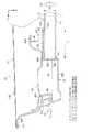
図4に示される如く、本実施形態では、ヒンジサイドパネル30の前壁部30Aのドア幅方向外側端部から、ドア後方へ向って側壁部30Cが形成されており、側壁部30Cの後端に平面視L字状の結合部52が形成されている。また、結合部52の前壁部52Aとヒンジサイドパネル30の前壁部30Aとの間には、ドア前後方向に伸びる補強用のリブ54が形成されており、結合部52の側壁部32Bは、前壁部52Aのドア幅方向外側端部からドア後方へ向って延設されている。
As shown in FIG. 4, in this embodiment, a
ベルトラインインナリインホース20の前端20Cは、結合部52の前壁部52Aに達しており、ベルトラインインナリインホース20の前端20Cは、結合部52の前壁部52Aのドア幅方向内側端部52Cと結合部P1において溶接により結合されている。
The
また、結合部52の側壁部52Bの後端部52Dは、ベルトラインインナリインフォースメント20のドア幅方向外側壁部20Fと結合部P4において溶接により結合されている。
Further, the rear end portion 52D of the side wall portion 52B of the
この結果、ベルトラインインナリインホース20とヒンジサイドパネル30との結合部P3と結合部P4は、ドア前後方向に距離L1オフセットしており、ドア幅方向に距離L2オフセットしている。
As a result, the connecting part P3 and the connecting part P4 between the beltline
従って、ベルトラインインナリインフォースメント20にドア幅方向(図4ではドア幅方向外側)から作用する荷重F1を、ドア前後方向及びドア幅方向にオフセットした2箇所の結合部P3、P4で受けることができるため、ベルトラインインナリインフォースメント20に車幅方向から作用する荷重F1に対するベルトラインインナリインフォースメント20とヒンジサイドパネル30との結合剛性及び結合強度を向上できるようになっている。また、ベルトラインインナリインフォースメント20にドア前後方向(図4ではドア前方)から作用する荷重F2を、ドア前後方向及びドア幅方向にオフセットした2箇所の結合部P3、P4で受けることができるため、ベルトラインインナリインフォースメント20に車体前後方向から作用する荷重F2に対するベルトラインインナリインフォースメント20とヒンジサイドパネル30との結合剛性及び結合強度を向上できるようになっている。また、ベルトラインインナリインフォースメント20に作用する捩れ荷重F3を、ドア前後方向及びドア幅方向にオフセットした2箇所の結合部P3、P4で受けることができるため、捩れ荷重F3に対するベルトラインインナリインフォースメント20とヒンジサイドパネル30との結合剛性及び結合強度を向上できるようになっている。
Accordingly, the load F1 acting on the beltline
次に、本実施形態の作用を説明する。 Next, the operation of this embodiment will be described.
本実施形態では、フロントサイドドア10のベルトライン10Cに沿って配設され、前部20Aがフロントサイドドア10の前部10Dに固定され、後部20Bがフロントサイドドア10の後部10Eに固定されたベルトラインインナリインフォースメント20の前部20Aと、フロントサイドドア10の前部10Dとなるヒンジサイドパネル30との前側結合部が、ドア前後方向及びドア幅方向にオフセットした2箇所の結合部P3、P4で固定されている。
In the present embodiment, the
この結果、ベルトラインインナリインフォースメント20にドア幅方向(図4ではドア幅方向外側)から作用する荷重F1を、ドア前後方向及びドア幅方向にオフセットした2箇所の結合部P3、P4で受けることができる。このため、ベルトラインインナリインフォースメント20に車幅方向から作用する荷重F1に対するベルトラインインナリインフォースメント20とヒンジサイドパネル30との結合剛性及び結合強度を向上できる。
As a result, the load F1 acting on the beltline
また、ベルトラインインナリインフォースメント20にドア前後方向(図4ではドア前方)から作用する荷重F2を、ドア前後方向及びドア幅方向にオフセットした2箇所の結合部P3、P4で受けることができる。このため、ベルトラインインナリインフォースメント20に車体前後方向から作用する荷重F2に対するベルトラインインナリインフォースメント20とヒンジサイドパネル30との結合剛性及び結合強度を向上できる。
Further, a load F2 acting on the beltline
また、ベルトラインインナリインフォースメント20に作用する捩れ荷重F3を、ドア前後方向及びドア幅方向にオフセットした2箇所の結合部P3、P4で受けることができる。このため、捩れ荷重F3に対するベルトラインインナリインフォースメント20とヒンジサイドパネル30との結合剛性及び結合強度を向上できる。
Further, the torsional load F3 acting on the beltline
従って、本実施形態では、ベルトラインインナリインフォースメント20とヒンジサイドパネル30との結合剛性及び結合強度を向上できる。
Therefore, in this embodiment, the joint rigidity and the joint strength between the beltline
また、本実施形態では、ベルトラインインナリインフォースメント20が閉断面部22を有する閉断面構造であるため、ベルトラインインナリインフォースメント20の剛性及び強度が向上すると共に結合剛性及び結合強度も向上する。この結果、フロントサイドドア10のドアフレームの剛性及び強度が向上する。
Moreover, in this embodiment, since the beltline
以上に於いては、本発明を特定の実施形態について詳細に説明したが、本発明は上記実施形態に限定されるものではなく、本発明の範囲内にて他の種々の実施形態が可能であることは当業者にとって明らかである。例えば、上記各実施形態では、ベルトラインインナリインフォースメント20を閉断面部22を有する閉断面構造としてが、これに代えて、図5に示される如く、ベルトラインインナリインフォースメント20を閉断面部を持たない開断面構造としても良い。
Although the present invention has been described in detail with respect to specific embodiments, the present invention is not limited to the above-described embodiments, and various other embodiments are possible within the scope of the present invention. It will be apparent to those skilled in the art. For example, in each of the above-described embodiments, the beltline
また、上記各実施形態では、ベルトラインインナリインフォースメント20の前部20Aと、フロントサイドドア10の前部10Dとなるヒンジサイドパネル30との前側結合部を、ドア前後方向及びドア幅方向にオフセットした2箇所の結合部で固定したが、これに代えて、ベルトラインインナリインフォースメント20の前部20Aと、フロントサイドドア10の前部10Dとなるヒンジサイドパネル30との前側結合部を、ドア前後方向及びドア幅方向にオフセットした2箇所以上の結合部で固定した構成としても良い。
Moreover, in each said embodiment, the front side coupling | bond part of the
また、上記各実施形態では、ベルトラインインナリインフォースメント20の前部20Aと、フロントサイドドア10の前部10Dとの前側結合部を、ドア前後方向及びドア幅方向にオフセットした2箇所の結合部で固定したが、これに代えて、ベルトラインインナリインフォースメント20の後部20Bと、フロントサイドドア10の後部10Eとの後側結合部を、ドア前後方向及びドア幅方向にオフセットした2箇所以上の結合部で固定した構成としても良い。
Moreover, in each said embodiment, the two connection parts which offset the front side connection part of the
また、ベルトラインインナリインフォースメント20の前部20Aと、フロントサイドドア10の前部10Dとの前側結合部と、ベルトラインインナリインフォースメント20の後部20Bと、フロントサイドドア10の後部10Eとの後側結合部との双方をドア前後方向及びドア幅方向にオフセットした2箇所以上の結合部で固定した構成としても良い。
In addition, the
また、上記各実施形態では、本発明の車両用ドア構造をフロントサイドドア10に適用したが、本発明の車両用ドア構造は、フロントサイドドア以外にリヤサイドドア等の他の車両用ドアにも適用可能である。
In each of the above embodiments, the vehicle door structure of the present invention is applied to the
10 フロントサイドドア(ドア)
10A フロントサイドドアのドア本体
10B フロントサイドドアのウインドフレーム
10C ベルトライン
10D フロントサイドドアの前部
10E フロントサイドドアの後部
12 ドアアウタパネル
14 ドアインナパネル
20 ベルトラインインナリインフォースメント
22 ベルトラインインナリインフォースメントの閉断面部
30 ヒンジサイドパネル
32 ヒンジサイドパネルの結合部
32A ヒンジサイドパネルの結合部の前壁部
32B ヒンジサイドパネルの結合部の側壁部
52 ヒンジサイドパネルの結合部
52A ヒンジサイドパネルの結合部の前壁部
52B ヒンジサイドパネルの結合部の側壁部
10 Front side door (door)
10A Front side
Claims (2)
前記リインフォースメントの前部と前記ドアの前部との前側結合部と、前記リインフォースメントの後部と前記ドアの後部との後側結合部と、の少なくとも一方が、前記ドアの前後方向及び前記ドアの幅方向にオフセットした2箇所以上で固定されていることを特徴とする車両用ドア構造。 Reinforcement is provided along the front-rear direction of the door, the front part is fixed to the front part of the door and the rear part is fixed to the rear part of the door,
At least one of a front coupling portion between the front portion of the reinforcement and the front portion of the door, and a rear coupling portion between the rear portion of the reinforcement and the rear portion of the door, the front-rear direction of the door and the door A vehicle door structure characterized by being fixed at two or more locations offset in the width direction.
Priority Applications (1)
| Application Number | Priority Date | Filing Date | Title |
|---|---|---|---|
| JP2004120238A JP2005297895A (en) | 2004-04-15 | 2004-04-15 | Vehicle door structure |
Applications Claiming Priority (1)
| Application Number | Priority Date | Filing Date | Title |
|---|---|---|---|
| JP2004120238A JP2005297895A (en) | 2004-04-15 | 2004-04-15 | Vehicle door structure |
Publications (1)
| Publication Number | Publication Date |
|---|---|
| JP2005297895A true JP2005297895A (en) | 2005-10-27 |
Family
ID=35329950
Family Applications (1)
| Application Number | Title | Priority Date | Filing Date |
|---|---|---|---|
| JP2004120238A Pending JP2005297895A (en) | 2004-04-15 | 2004-04-15 | Vehicle door structure |
Country Status (1)
| Country | Link |
|---|---|
| JP (1) | JP2005297895A (en) |
Cited By (1)
| Publication number | Priority date | Publication date | Assignee | Title |
|---|---|---|---|---|
| JP2007253801A (en) * | 2006-03-23 | 2007-10-04 | Mitsubishi Motors Corp | Vehicle door structure |
-
2004
- 2004-04-15 JP JP2004120238A patent/JP2005297895A/en active Pending
Cited By (1)
| Publication number | Priority date | Publication date | Assignee | Title |
|---|---|---|---|---|
| JP2007253801A (en) * | 2006-03-23 | 2007-10-04 | Mitsubishi Motors Corp | Vehicle door structure |
Similar Documents
| Publication | Publication Date | Title |
|---|---|---|
| US7390049B2 (en) | Vehicle door | |
| CN101395021B (en) | Vehicle body side structure | |
| WO2010055589A1 (en) | Structural member for vehicle | |
| JP3909649B2 (en) | Car side body structure | |
| JP3951507B2 (en) | Car side body structure | |
| JP2010143453A (en) | Vehicle door structure | |
| JP6698393B2 (en) | Body side structure | |
| CN115071384B (en) | Door structure | |
| JP4839866B2 (en) | Vehicle side structure | |
| JP4093017B2 (en) | Rear body structure | |
| JP2001301654A (en) | Car body side structure | |
| CN115071383A (en) | Vehicle door structure | |
| JP2001294178A (en) | Body side structure | |
| JP2007223406A (en) | Door sash mounting structure | |
| JP4400355B2 (en) | Automobile front pillar structure | |
| JP4702189B2 (en) | Door belt line structure | |
| JP3988106B2 (en) | Side door structure | |
| KR100422541B1 (en) | door of vehicle | |
| JP2005161889A (en) | Connecting structure at the rear of the car body | |
| JP4305149B2 (en) | Body side structure | |
| JP6157875B2 (en) | Front door structure of center pillarless vehicle | |
| KR100521927B1 (en) | Strength reinforcement structure of Tail gate upper corner part | |
| JP4525374B2 (en) | Body structure | |
| JP2007098982A (en) | Body structure | |
| JP2003063442A (en) | Vehicle pillar structure |