JP2005297878A - Bearing device for vehicle wheel with brake rotor - Google Patents
Bearing device for vehicle wheel with brake rotor Download PDFInfo
- Publication number
- JP2005297878A JP2005297878A JP2004119771A JP2004119771A JP2005297878A JP 2005297878 A JP2005297878 A JP 2005297878A JP 2004119771 A JP2004119771 A JP 2004119771A JP 2004119771 A JP2004119771 A JP 2004119771A JP 2005297878 A JP2005297878 A JP 2005297878A
- Authority
- JP
- Japan
- Prior art keywords
- wheel
- brake rotor
- brake
- mounting flange
- bearing device
- Prior art date
- Legal status (The legal status is an assumption and is not a legal conclusion. Google has not performed a legal analysis and makes no representation as to the accuracy of the status listed.)
- Pending
Links
- 229910000831 Steel Inorganic materials 0.000 claims abstract description 5
- 239000010959 steel Substances 0.000 claims abstract description 5
- 238000005096 rolling process Methods 0.000 claims description 48
- 238000003780 insertion Methods 0.000 claims description 16
- 230000037431 insertion Effects 0.000 claims description 16
- 230000001105 regulatory effect Effects 0.000 claims description 10
- 238000003825 pressing Methods 0.000 claims description 4
- 238000010276 construction Methods 0.000 abstract 1
- 210000000078 claw Anatomy 0.000 description 5
- 238000003754 machining Methods 0.000 description 3
- 238000000034 method Methods 0.000 description 3
- OKTJSMMVPCPJKN-UHFFFAOYSA-N Carbon Chemical compound [C] OKTJSMMVPCPJKN-UHFFFAOYSA-N 0.000 description 2
- 229910000954 Medium-carbon steel Inorganic materials 0.000 description 2
- 229910052799 carbon Inorganic materials 0.000 description 2
- 230000006698 induction Effects 0.000 description 2
- 238000005259 measurement Methods 0.000 description 2
- 238000012986 modification Methods 0.000 description 2
- 230000004048 modification Effects 0.000 description 2
- 230000036316 preload Effects 0.000 description 2
- 239000013585 weight reducing agent Substances 0.000 description 2
- -1 S53C Chemical compound 0.000 description 1
- 229910000639 Spring steel Inorganic materials 0.000 description 1
- 238000005452 bending Methods 0.000 description 1
- 238000005553 drilling Methods 0.000 description 1
- 239000000428 dust Substances 0.000 description 1
- 238000005242 forging Methods 0.000 description 1
- 239000004519 grease Substances 0.000 description 1
- 230000001050 lubricating effect Effects 0.000 description 1
- 239000000463 material Substances 0.000 description 1
- 230000002093 peripheral effect Effects 0.000 description 1
- 238000012545 processing Methods 0.000 description 1
- 102220097517 rs876659265 Human genes 0.000 description 1
- 238000010079 rubber tapping Methods 0.000 description 1
- 239000000725 suspension Substances 0.000 description 1
Images

Classifications
-
- F—MECHANICAL ENGINEERING; LIGHTING; HEATING; WEAPONS; BLASTING
- F16—ENGINEERING ELEMENTS AND UNITS; GENERAL MEASURES FOR PRODUCING AND MAINTAINING EFFECTIVE FUNCTIONING OF MACHINES OR INSTALLATIONS; THERMAL INSULATION IN GENERAL
- F16C—SHAFTS; FLEXIBLE SHAFTS; ELEMENTS OR CRANKSHAFT MECHANISMS; ROTARY BODIES OTHER THAN GEARING ELEMENTS; BEARINGS
- F16C19/00—Bearings with rolling contact, for exclusively rotary movement
- F16C19/02—Bearings with rolling contact, for exclusively rotary movement with bearing balls essentially of the same size in one or more circular rows
- F16C19/14—Bearings with rolling contact, for exclusively rotary movement with bearing balls essentially of the same size in one or more circular rows for both radial and axial load
- F16C19/18—Bearings with rolling contact, for exclusively rotary movement with bearing balls essentially of the same size in one or more circular rows for both radial and axial load with two or more rows of balls
- F16C19/181—Bearings with rolling contact, for exclusively rotary movement with bearing balls essentially of the same size in one or more circular rows for both radial and axial load with two or more rows of balls with angular contact
- F16C19/183—Bearings with rolling contact, for exclusively rotary movement with bearing balls essentially of the same size in one or more circular rows for both radial and axial load with two or more rows of balls with angular contact with two rows at opposite angles
- F16C19/184—Bearings with rolling contact, for exclusively rotary movement with bearing balls essentially of the same size in one or more circular rows for both radial and axial load with two or more rows of balls with angular contact with two rows at opposite angles in O-arrangement
- F16C19/186—Bearings with rolling contact, for exclusively rotary movement with bearing balls essentially of the same size in one or more circular rows for both radial and axial load with two or more rows of balls with angular contact with two rows at opposite angles in O-arrangement with three raceways provided integrally on parts other than race rings, e.g. third generation hubs
-
- Y—GENERAL TAGGING OF NEW TECHNOLOGICAL DEVELOPMENTS; GENERAL TAGGING OF CROSS-SECTIONAL TECHNOLOGIES SPANNING OVER SEVERAL SECTIONS OF THE IPC; TECHNICAL SUBJECTS COVERED BY FORMER USPC CROSS-REFERENCE ART COLLECTIONS [XRACs] AND DIGESTS
- Y02—TECHNOLOGIES OR APPLICATIONS FOR MITIGATION OR ADAPTATION AGAINST CLIMATE CHANGE
- Y02T—CLIMATE CHANGE MITIGATION TECHNOLOGIES RELATED TO TRANSPORTATION
- Y02T10/00—Road transport of goods or passengers
- Y02T10/80—Technologies aiming to reduce greenhouse gasses emissions common to all road transportation technologies
- Y02T10/86—Optimisation of rolling resistance, e.g. weight reduction
Landscapes
- Braking Arrangements (AREA)
- Rolling Contact Bearings (AREA)
Abstract
Description
本発明は、自動車等の車輪を回転自在に支承するブレーキロータ付き車輪用軸受装置に関するものである。 The present invention relates to a wheel bearing device with a brake rotor that rotatably supports a wheel of an automobile or the like.
自動車の車輪用軸受装置には、駆動輪用のものと従動輪用のものとがあり、それぞれ種々の形式のものがある。この種の車輪用軸受装置は、車輪軸受メーカーから自動車メーカーの自動車組立工場に納入され、その車輪取付フランジの側面には、自動車組立工場において別部品として納入されたブレーキロータがボルトによって固定される。ところが、組立後に、このブレーキロータの側面に面振れがあると、高速走行における制動時の振動の原因となったり、ブレーキの偏摩耗の原因になったりする。また、面振れの程度によっては、低速走行でも振動が発生する場合がある。 There are two types of wheel bearing devices for automobiles, one for driving wheels and one for driven wheels. This type of wheel bearing device is delivered from a wheel bearing manufacturer to an automobile manufacturer's automobile assembly factory, and a brake rotor delivered as a separate part at the automobile assembly factory is fixed to the side surface of the wheel mounting flange by bolts. . However, if there is surface vibration on the side surface of the brake rotor after assembly, it may cause vibration during braking during high-speed running or cause uneven wear of the brake. Further, depending on the degree of surface runout, vibration may occur even at low speeds.
こうした問題を解決したものとして、本出願人は図10に示すようなブレーキロータ付き車輪用軸受装置を提案している。このブレーキロータ付き車輪用軸受装置は、外周に懸架装置(図示せず)に取り付けられる車体取付フランジ51bを一体に有し、内周に複列の外側転走面51a、51aが形成された外方部材51と、一端部に車輪(図示せず)を取り付けるための車輪取付フランジ52を一体に有し、外周に前記複列の外側転走面51a、51aに対向する一方の内側転走面53aと、この内側転走面51aから軸方向に延びる円筒状の小径段部53bが形成されたハブ輪53、およびこのハブ輪53の小径段部53bに圧入され、外周に前記複列の外側転走面51a、51aに対向する他方の内側転走面54aが形成された内輪54とからなる内方部材55と、この内方部材55と外方部材51との間に転動自在に介装された複列の転動体(ボール)56、56と、外方部材51の両端部に装着されたシール57、57とからなる。
As a solution to these problems, the present applicant has proposed a wheel bearing device with a brake rotor as shown in FIG. This wheel bearing device with a brake rotor is integrally provided with a vehicle body mounting flange 51b attached to a suspension device (not shown) on the outer periphery, and an outer periphery in which double-row outer
車輪取付フランジ52には、周方向等配に車輪を固定するためのハブボルト58が植設され、車輪取付フランジ52のアウトボード側にブレーキロータ59を支持する円筒状のブレーキパイロット部60と、このブレーキパイロット部60からさらにアウトボード側にホイールパイロット部61が一体に形成されている。そして、フランジ側面52aにブレーキロータ59がボルト62によって固定されている。
The
ここで、固定部材となる外方部材51を基準に回転駆動させた状態で、ブレーキロータ59の側面59a、59aの面振れが規格値内、例えば50μm以下に規制されている。このように、ブレーキロータ付き車輪用軸受装置は、車輪軸受メーカーから出荷される際に、予めブレーキロータ59の側面59aの振れ幅が規格値内に規制されているので信頼性が高く、自動車組立工場において面倒なブレーキロータ59の振れ調整を行なう必要がなくなる。
しかしながら、こうした従来のブレーキロータ付き車輪用軸受装置において、ブレーキロータ59を車輪取付フランジ52のフランジ側面52aに固定する手段としてボルト62が用いられているため、孔加工やタップ加工が必要となりコスト高騰を招来している。また、固定用のボルト62はハブボルト58間に締結されるため、例えば、軽量化を狙って車輪取付フランジのハブボルト間の余肉が除去されたフランジ構造のものには適用ができなかった。
However, in such a conventional wheel bearing device with a brake rotor, the
本発明は、このような事情に鑑みてなされたもので、装置の軽量・コンパクト化を図ると共に、ブレーキロータの固定に係るコストの低減を図ったブレーキロータ付き車輪用軸受装置を提供することを目的としている。
また、本発明の他の目的は、ブレーキロータの面振れによる振動およびブレーキの偏摩耗を防止すること。
さらに、本発明の他の目的は、自動車組立工場において面倒なブレーキロータの振れ調整を行なう必要のない、信頼性の高いブレーキロータ付き車輪用軸受装置を提供することである。
The present invention has been made in view of such circumstances, and provides a bearing device for a wheel with a brake rotor which is intended to reduce the weight and size of the device and to reduce the cost for fixing the brake rotor. It is aimed.
Another object of the present invention is to prevent vibration due to runout of the brake rotor and uneven wear of the brake.
It is another object of the present invention to provide a highly reliable wheel bearing device with a brake rotor that does not require troublesome adjustment of the brake rotor in an automobile assembly plant.
係る目的を達成すべく、本発明のうち請求項1記載の発明は、内周に複列の外側転走面が形成された外方部材と、外周に前記複列の外側転走面に対向する内側転走面が形成された内方部材と、この内方部材および前記外方部材のそれぞれの転走面間に転動自在に収容された複列の転動体とを備え、当該内方部材または外方部材のいずれか一方に車輪取付フランジが一体に設けられ、この車輪取付フランジにブレーキロータが取り付けられたブレーキロータ付き車輪用軸受装置において、前記車輪取付フランジのアウトボード側に前記ブレーキロータを支持する円筒状のブレーキパイロット部と、このブレーキパイロット部からさらにアウトボード側にこのブレーキパイロット部よりも小径にホイールパイロット部が一体に形成されると共に、このホイールパイロット部に止め輪が嵌着され、この止め輪によって前記ブレーキロータが前記車輪取付フランジに固定されている構成を採用した。 In order to achieve the object, the invention according to claim 1 of the present invention is such that an outer member having a double row outer rolling surface formed on the inner periphery and an outer member facing the double row outer rolling surface on the outer periphery. An inner member on which an inner rolling surface is formed, and a double row rolling element that is slidably accommodated between the inner member and the outer member. In a wheel bearing device with a brake rotor in which a wheel mounting flange is integrally provided on either the member or the outer member, and a brake rotor is mounted on the wheel mounting flange, the brake is mounted on the outboard side of the wheel mounting flange. A cylindrical brake pilot portion that supports the rotor, and a wheel pilot portion that is smaller in diameter than the brake pilot portion on the outboard side further from the brake pilot portion, Fitted spokes of the wheel pilot portion is adopted a configuration in which the brake rotor is fixed to the wheel mounting flange by the retaining ring.
このように、車輪取付フランジのアウトボード側にブレーキロータを支持する円筒状のブレーキパイロット部と、このブレーキパイロット部からさらにアウトボード側にこのブレーキパイロット部よりも小径にホイールパイロット部が一体に形成されると共に、このホイールパイロット部に止め輪が嵌着され、この止め輪によってブレーキロータが車輪取付フランジに固定されているので、ブレーキロータは、従来のようにボルト等で締結することなく、簡便に車輪取付フランジに固定することができる。したがって、ブレーキロータにボルト孔等を加工する工数およびブレーキロータの組立工数の削減を図ることができ、低コスト化を達成することができる。 In this way, a cylindrical brake pilot portion that supports the brake rotor on the outboard side of the wheel mounting flange, and a wheel pilot portion that is smaller in diameter than the brake pilot portion are formed integrally from the brake pilot portion to the outboard side. At the same time, a retaining ring is fitted to the wheel pilot part, and the brake rotor is fixed to the wheel mounting flange by the retaining ring. It can be fixed to the wheel mounting flange. Therefore, it is possible to reduce the man-hours for machining the bolt holes and the like in the brake rotor and the assembly man-hours of the brake rotor, and the cost can be reduced.
また、請求項2に記載の発明は、前記止め輪は、鋼板をプレス加工によって皿状に形成され、その内周に複数の凹所が打ち抜かれていると共に、その内径が前記ホイールパイロット部の外径より僅かに小径に設定されているので、凹所間に形成される爪部がホイールパイロット部に食い込み、ブレーキロータはガタなく車輪取付フランジに固定される。 According to a second aspect of the present invention, the retaining ring is formed in a dish shape by pressing a steel plate, and a plurality of recesses are punched out on the inner periphery thereof, and the inner diameter of the retaining ring is that of the wheel pilot portion. Since the diameter is set slightly smaller than the outer diameter, the claw portion formed between the recesses bites into the wheel pilot portion, and the brake rotor is fixed to the wheel mounting flange without play.
また、請求項3に記載の発明は、前記止め輪は有端のC形に形成され、前記ホイールパイロット部の外周に形成された環状溝に嵌着されているので、拡縮自在な止め輪をホイールパイロット部の環状溝に容易に嵌着させることができ、また抜け止めとしての信頼性も高い。 According to a third aspect of the present invention, the retaining ring is formed in a C-shaped end and is fitted in an annular groove formed on the outer periphery of the wheel pilot portion. It can be easily fitted in the annular groove of the wheel pilot part, and has high reliability as a retaining stopper.
また、請求項4に記載の発明は、前記車輪取付フランジの円周等配にハブボルトが固定されるボルト挿通孔が形成され、このボルト挿通孔の周辺を避けて各ボルト挿通孔間において、当該車輪取付フランジの外周に切欠き部が形成されているので、ハブ輪の軽量化を図ることができる。また、車輪用軸受装置を組み立てた状態で、外方部材をナックルに締結する際に、これら車輪取付フランジに邪魔されることなく、工具にて容易にナックルボルトを締結することができ、組立作業を簡便化することができる。
Further, in the invention according to
また、請求項5に記載の発明は、前記ブレーキロータの円周等配にハブボルトが挿通される円孔が形成され、この円孔の周辺を避けて各円孔間において、当該ブレーキロータの内周に切欠き部が形成されているので、ブレーキロータの軽量化を図ることができる。 According to a fifth aspect of the present invention, a circular hole through which a hub bolt is inserted is formed on the circumference of the brake rotor and the inner circumference of the brake rotor is avoided between the circular holes by avoiding the periphery of the circular hole. Since the notch is formed in the circumference, the weight of the brake rotor can be reduced.
また、請求項6に記載の発明は、前記ブレーキロータの側面の振れ幅が、固定側部材を基準に回転駆動させた状態で規格値内に規制されているので信頼性が高く、また、自動車組立工場において面倒なブレーキロータの振れ調整を行なう必要がなくなる。
Further, the invention according to
本発明に係るブレーキロータ付き車輪用軸受装置は、内周に複列の外側転走面が形成された外方部材と、外周に前記複列の外側転走面に対向する内側転走面が形成された内方部材と、この内方部材および前記外方部材のそれぞれの転走面間に転動自在に収容された複列の転動体とを備え、当該内方部材または外方部材のいずれか一方に車輪取付フランジが一体に設けられ、この車輪取付フランジにブレーキロータが取り付けられたブレーキロータ付き車輪用軸受装置において、前記車輪取付フランジのアウトボード側に前記ブレーキロータを支持する円筒状のブレーキパイロット部と、このブレーキパイロット部からさらにアウトボード側にこのブレーキパイロット部よりも小径にホイールパイロット部が一体に形成されると共に、このホイールパイロット部に止め輪が嵌着され、この止め輪によって前記ブレーキロータが前記車輪取付フランジに固定されているので、ブレーキロータは、従来のようにボルト等で締結することなく、簡便に車輪取付フランジに固定することができる。したがって、ブレーキロータにボルト孔等を加工する工数およびブレーキロータの組立工数の削減を図ることができ、低コスト化を達成することができる。 The wheel bearing device with a brake rotor according to the present invention includes an outer member having a double row outer rolling surface formed on the inner periphery, and an inner rolling surface facing the double row outer rolling surface on the outer periphery. An inner member formed, and a double row rolling element that is rotatably accommodated between the rolling surfaces of the inner member and the outer member, and the inner member or the outer member. A wheel bearing device with a brake rotor, in which a wheel mounting flange is integrally provided on either side, and a brake rotor is mounted on the wheel mounting flange, a cylindrical shape that supports the brake rotor on the outboard side of the wheel mounting flange The brake pilot part and the wheel pilot part having a smaller diameter than the brake pilot part are integrally formed on the outboard side from the brake pilot part. Since a retaining ring is fitted to the pilot part and the brake rotor is fixed to the wheel mounting flange by this retaining ring, the brake rotor can be easily mounted on the wheel without being fastened with bolts or the like as in the prior art. Can be fixed to the flange. Therefore, it is possible to reduce the man-hours for machining the bolt holes and the like in the brake rotor and the assembly man-hours of the brake rotor, and the cost can be reduced.
外周に車体取付フランジを一体に有し、内周に複列の外側転走面が形成された外方部材と、一端部に車輪取付フランジを一体に有し、外周に前記複列の外側転走面に対向する一方の内側転走面と、この内側転走面から軸方向に延びる円筒状の小径段部が形成されたハブ輪、およびこのハブ輪の小径段部に圧入され、外周に前記複列の外側転走面に対向する他方の内側転走面が形成された内輪とからなる内方部材と、この内方部材および前記外方部材のそれぞれの転走面間に転動自在に収容された複列の転動体とを備え、前記車輪取付フランジにブレーキロータが取り付けられたブレーキロータ付き車輪用軸受装置において、前記車輪取付フランジのアウトボード側に前記ブレーキロータを支持する円筒状のブレーキパイロット部と、このブレーキパイロット部からさらにアウトボード側にこのブレーキパイロット部よりも小径にホイールパイロット部が一体に形成されると共に、このホイールパイロット部に、鋼板をプレス加工によって皿状に形成され、内周に複数の凹所を有すると共に、その内径がホイールパイロット部の外径より僅かに小径に設定された止め輪が嵌着されている。 A vehicle body mounting flange is integrally formed on the outer periphery, an outer member having a double row outer rolling surface formed on the inner periphery, a wheel mounting flange is integrally formed on one end, and the double row outer rolling is formed on the outer periphery. One inner rolling surface facing the running surface, a hub ring formed with a cylindrical small-diameter stepped portion extending in the axial direction from the inner rolling surface, and a small-diameter stepped portion of the hub wheel are press-fitted to the outer periphery. An inner member comprising an inner ring formed with the other inner rolling surface facing the double row outer rolling surface, and freely rollable between the respective rolling surfaces of the inner member and the outer member. In a wheel bearing device with a brake rotor, wherein the brake rotor is supported on the outboard side of the wheel mounting flange. This brake pilot section A wheel pilot part is integrally formed with a smaller diameter than the brake pilot part on the outboard side from the pilot part, and a steel plate is formed in the wheel pilot part by pressing to form a plurality of plates on the inner periphery. A retaining ring having a recess and having an inner diameter slightly smaller than the outer diameter of the wheel pilot portion is fitted.
以下、本発明の実施の形態を図面に基づいて詳細に説明する。
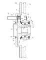
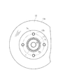
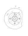
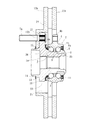
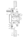
図1は、本発明に係るブレーキロータ付き車輪用軸受装置の第1の実施形態を示す縦断面図、図2は、図1の側面図である。なお、以下の説明では、車両に組み付けた状態で車両の外側寄りとなる側をアウトボード側(図面左側)、中央寄り側をインボード側(図面右側)という。
Hereinafter, embodiments of the present invention will be described in detail with reference to the drawings.
FIG. 1 is a longitudinal sectional view showing a first embodiment of a wheel bearing device with a brake rotor according to the present invention, and FIG. 2 is a side view of FIG. In the following description, the side closer to the outer side of the vehicle when assembled to the vehicle is referred to as the outboard side (left side in the drawing), and the side closer to the center is referred to as the inboard side (right side in the drawing).
このブレーキロータ付き車輪用軸受装置は駆動輪用であって、ハブ輪1と複列の転がり軸受2とをユニット化した、所謂第3世代と称される構成を備えている。
複列の転がり軸受2は、外方部材4と内方部材3と複列の転動体(ボール)5、5とを有し、外方部材4は、S53C等の炭素0.40〜0.80wt%を含む中炭素鋼からなり、外周に車体(図示せず)に取り付けるための車体取付フランジ4bを一体に有している。内周には複列の外側転走面4a、4aが形成され、高周波焼入れによって表面硬さを54〜64HRCの範囲に硬化層が形成されている。
This wheel bearing device with a brake rotor is for a driving wheel, and has a so-called third generation configuration in which the
The double-
一方、内方部材3は、前記した外方部材4の外側転走面4a、4aに対向する複列の内側転走面1a、6aが形成されている。これら複列の内側転走面1a、6aのうち一方の内側転走面1aはハブ輪1の外周に、他方の内側転走面6aは、ハブ輪1に圧入された内輪6の外周にそれぞれ一体に形成されている。この場合、内方部材3はハブ輪1と内輪6を指す。
On the other hand, the
ハブ輪1は、S53C等の炭素0.40〜0.80wt%を含む中炭素鋼からなり、アウトボード側の端部に車輪(図示せず)を取り付けるための車輪取付フランジ7を一体に有し、外周に内側転走面1aと、この内側転走面1aから軸方向に延びる円筒状の小径段部1bが形成されている。そして、この小径段部1bに内輪6が圧入されると共に、小径段部1bの端部を径方向に塑性変形させて加締部8が形成されている。この加締部8により、内輪6はハブ輪1に対して軸方向に固定され、所謂セルフリテイン構造をなしている。これにより、従来のようにナット等で強固に緊締して予圧量を管理する必要がないため、軽量・コンパクト化を図ることができると共に、ハブ輪1の強度・耐久性を向上させ、かつ長期間その予圧量を維持することができる。
The
外方部材4および内方部材3の両転走面間には複列の転動体5、5がそれぞれ収容され、保持器9、9によって転動自在に保持されている。また、外方部材4の端部にはシール10、11が装着され、軸受内部に封入された潤滑グリースの漏洩と、外部から軸受内部に雨水やダスト等が侵入するのを防止している。
Double
また、ハブ輪1には、アウトボード側のシール10が摺接するシールランド部から内側転走面1aおよび小径段部1bに亙って高周波焼入れによって表面硬さを54〜64HRCの範囲に硬化層が形成されている。これにより、車輪取付フランジ7の基部となるシールランド部は耐摩耗性が向上するばかりでなく、車輪取付フランジ7に負荷される回転曲げ荷重に対して充分な機械的強度を有し、ハブ輪1の耐久性が一層向上する。なお、加締部8は、鍛造後の素材表面硬さ24HRC以下の未焼入れ部としている。これにより、加締部8を塑性変形させる時の加工性が向上すると共に、加工時におけるクラック等の発生を防止してその品質の信頼性が向上する。
Also, the
ハブ輪1における車輪取付フランジ7には、周方向等配に車輪を固定するためのハブボルト7aが植設され、車輪取付フランジ7のアウトボード側には、ブレーキロータ12を支持する円筒状のブレーキパイロット部13と、このブレーキパイロット部13からさらにアウトボード側に、ブレーキパイロット部13よりも小径にホイールパイロット部14が一体に形成されている。
A
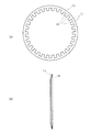
本実施形態では、ブレーキロータ12が車輪取付フランジ7のフランジ側面7bに止め輪15によって固定されている。この止め輪15は、図3に示すように、ばね鋼等の鋼板をプレス加工によって皿状に形成され、内周に複数の凹所16が打ち抜かれている。その結果、これらの凹所16間には複数の爪部17が形成されている。ここで、爪部17の内径は、ホイールパイロット部14の外径より僅かに小径に設定されている。
In the present embodiment, the
次に、ブレーキロータ12の組立手順について説明する。
1.先ず、ブレーキロータ12に穿設された円孔12bと車輪取付フランジ7のハブボルト7aの位相を合わせた状態でブレーキロータ12をブレーキパイロット部13に嵌合させる。
2.次に、フランジ側面7bにブレーキロータ12を衝合させ、この状態で止め輪15をホイールパイロット部14に嵌挿させる。
3.その後、止め輪15の内周部をリング状の治具(図示せず)等で押圧し、爪部17を弾性変形させてホイールパイロット部14に嵌着させる。
Next, the assembly procedure of the
1. First, the
2. Next, the
3. Thereafter, the inner peripheral portion of the retaining
本実施形態では、止め輪15が皿状に形成され、その内径がホイールパイロット部14の外径より僅かに小径に設定されているため、爪部17がホイールパイロット部14に食い込み、ブレーキロータ12はガタなくフランジ側面7bに固定される。これにより、ブレーキロータ12は、従来のようにボルト等で締結することなく、簡便に車輪取付フランジ7に固定することができる。したがって、ブレーキロータ12にボルト孔等を加工する工数およびブレーキロータ12の組立工数の削減を図ることができ、低コスト化を達成することができる。
In this embodiment, the retaining
次に、ブレーキロータ12における側面12aの面振れの規制方法について説明する。
1.先ず、車輪用軸受装置を組み立てた状態で、固定側部材となる外方部材4を測定台(図示せず)に固定する。
2.ハブ輪1における車輪取付フランジ7のフランジ側面7bにダイヤルゲージ(図示せず)を当て、固定された外方部材4を基準に、内方部材3を一回転させてフランジ側面7bの軸方向の振れ幅が所定の規格値内、例えば、30μm以下に規制される。
3.次に、ブレーキロータ12単体において、その側面12aの軸方向の振れ幅を測定し、前記フランジ側面7bの振れ幅に基いて所望の振れ幅を有するブレーキロータ12を適宜選択する。
4.その後、前述したブレーキロータ12の組立手順に沿ってブレーキロータ12を車輪取付フランジ7のフランジ側面7bに固定する。
5.再度、外方部材4を測定台に固定すると共に、ブレーキロータ12の側面12aにダイヤルゲージを当て、固定された外方部材4を基準に、内方部材3を一回転させ、ブレーキロータ12における側面12aの軸方向の振れ幅が所定の規格値内、例えば、50μm以下に規制され管理される。
Next, a method for regulating surface runout of the
1. First, in a state where the wheel bearing device is assembled, the
2. A dial gauge (not shown) is applied to the
3. Next, in the
4). Thereafter, the
5). Again, the
このように、本実施形態におけるブレーキロータ付き車輪用軸受装置は、車輪軸受メーカーから出荷される際に、予めブレーキロータ12の側面12aの振れ幅が規格値内に規制されているので信頼性が高く、自動車組立工場において面倒なブレーキロータ12の振れ調整を行なう必要がなくなる。
As described above, the wheel bearing device with a brake rotor according to the present embodiment is reliable because the runout width of the
当然のことながら、ブレーキロータ12を車輪取付フランジ7に固定する前のフランジ側面7bの面振れ規格値、およびブレーキロータ12単体での側面12aの面振れ規格値双方を厳しく規制することにより、ブレーキロータ付き車輪用軸受装置におけるブレーキロータ12の側面12aの面振れを所定の規格値内に規制することができるが、フランジ側面7bとブレーキロータ12単体での側面12aのそれぞれの振れ幅に基き、両者を選択組み合わせしても良い。
As a matter of course, by strictly regulating both the surface runout standard value of the
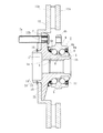
図4は本発明に係る車輪用軸受装置の第2の実施形態を示す縦断面図、図5は、図4の側面図である。なお、この実施形態は前述した実施形態とブレーキロータの固定手段のみが異なるだけで、その他同一部位、同一部品、あるいは同一の機能を有する部位には同じ符号を付けてその詳細な説明を省略する。 4 is a longitudinal sectional view showing a second embodiment of the wheel bearing device according to the present invention, and FIG. 5 is a side view of FIG. Note that this embodiment is different from the above-described embodiment only in the fixing means of the brake rotor, and the same parts, the same parts, or the parts having the same function are denoted by the same reference numerals and detailed description thereof is omitted. .
ハブ輪1’は、そのアウトボード側の端部に車輪取付フランジ7を一体に有し、この車輪取付フランジ7のアウトボード側には、ブレーキロータ12を支持する円筒状のブレーキパイロット部13と、このブレーキパイロット部13からさらにアウトボード側に、ブレーキパイロット部13よりも小径にホイールパイロット部14’が一体に形成されている。このホイールパイロット部14’の外周には後述する止め輪18が装着される環状溝19が形成されている。
The
本実施形態では、ブレーキロータ12が車輪取付フランジ7のフランジ側面7bに止め輪18によって固定されている。この止め輪18は有端のC形をなし、その端部には治具を係止するための係止孔18aが形成されている。前述した実施形態と同様、先ず、ブレーキロータ12に穿設された円孔12bと車輪取付フランジ7のハブボルト7aの位相を合わせた状態でブレーキロータ12をブレーキパイロット部13に嵌合させ、フランジ側面7bにブレーキロータ12を衝合させ、この状態で止め輪18の係止孔18aに治具(図示せず)を係止させて拡径させながら止め輪18をホイールパイロット部14’に嵌挿させる。その後、環状溝19の位置で治具を外し、この環状溝19に止め輪18を嵌着させる。
In the present embodiment, the
本実施形態では、止め輪18がC形の形状をなし拡縮自在であるため、ホイールパイロット部14’の環状溝19に容易に嵌着させることができる。したがって、ブレーキロータ12は、従来のようにボルト等で締結することなく、簡便に車輪取付フランジ7に固定することができ、また抜け止めとしての信頼性が高い。
In the present embodiment, the retaining
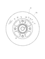
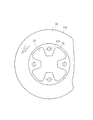
図6は本発明に係る車輪用軸受装置の第3の実施形態を示す縦断面図、図7は、図6の側面図である。なお、この実施形態は前述した第1の実施形態とハブ輪およびブレーキロータの形状が異なり、その他同一部位、同一部品、あるいは同一の機能を有する部位には同じ符号を付けてその詳細な説明を省略する。 FIG. 6 is a longitudinal sectional view showing a third embodiment of the wheel bearing device according to the present invention, and FIG. 7 is a side view of FIG. This embodiment is different from the first embodiment described above in the shapes of the hub wheel and the brake rotor, and other parts that are the same, the same parts, or the same function are denoted by the same reference numerals and detailed descriptions thereof are made. Omitted.
ハブ輪20は、そのアウトボード側の端部に車輪取付フランジ21を一体に有している。この車輪取付フランジ21は、図8に示すように、円周4箇所等配にハブボルト7aが固定されるボルト挿通孔22が形成され、このボルト挿通孔22の周辺を避けて、各ボルト挿通孔22間において、車輪取付フランジ21の外周にR形状の切欠き部23が形成されている。
The
切欠き部23は、ボルト挿通孔22のピッチ円直径Aより内径側で、かつ隣接するボルト挿通孔22の中心を結ぶ弦Bにその最深部23aが近接するように形成されている。これによりハブ輪20の軽量化を図ることができる。
The
一方、ブレーキロータ24は、図9に示すように、円周4箇所等配にハブボルト7aが挿通される円孔12bが形成され、この円孔12bの周辺を避けて、各円孔12b間において、ブレーキロータ24の内周に切欠き部25が形成されている。これによりブレーキロータ24の軽量化を図ることができる。
On the other hand, as shown in FIG. 9, the
本実施形態では、車輪取付フランジ21が、ハブボルト挿通孔22の近傍を除く部分を切欠いて、各ハブボルト挿通孔22間において、車輪取付フランジ21の外周にR形状の切欠き部23が形成され、また、ブレーキロータ24が、円孔12bの周辺を避けて、各円孔12b間において、ブレーキロータ24の内周に切欠き部25が形成されているので、ブレーキロータ付き車輪用軸受装置を組み立てた状態で、外方部材4をナックル(図示せず)に締結する際に、これら車輪取付フランジ21およびブレーキロータ24に邪魔されることなく、工具にて容易にナックルボルト(図示せず)を締結することができ、組立作業を簡便化することができる。
In the present embodiment, the
以上、本発明の実施の形態について説明を行ったが、本発明はこうした実施の形態に何等限定されるものではなく、あくまで例示であって、本発明の要旨を逸脱しない範囲内において、さらに種々なる形態で実施し得ることは勿論のことであり、本発明の範囲は、特許請求の範囲の記載によって示され、さらに特許請求の範囲に記載の均等の意味、および範囲内のすべての変更を含む。 The embodiment of the present invention has been described above, but the present invention is not limited to such an embodiment, and is merely an example, and various modifications can be made without departing from the scope of the present invention. Of course, the scope of the present invention is indicated by the description of the scope of claims, and further, the equivalent meanings described in the scope of claims and all modifications within the scope of the scope of the present invention are included. Including.
本発明に係るブレーキロータ付き車輪用軸受装置は、駆動輪用、従動輪用、転動体がボール、円錐ころ、あるいは内輪回転タイプ、外輪回転タイプに係らず、車輪取付フランジを一体に有する車輪用軸受装置に適用することができる。 The wheel bearing device with a brake rotor according to the present invention is for a drive wheel, a driven wheel, a wheel having a wheel mounting flange integrally, regardless of whether the rolling element is a ball, a tapered roller, an inner ring rotating type, or an outer ring rotating type. It can be applied to a bearing device.
1、1’、20・・・・・・・・・・ハブ輪
1a、6a・・・・・・・・・・・・内側転走面
1b・・・・・・・・・・・・・・・小径段部
2・・・・・・・・・・・・・・・・複列の転がり軸受
3・・・・・・・・・・・・・・・・内方部材
4・・・・・・・・・・・・・・・・外方部材
4a・・・・・・・・・・・・・・・外側転走面
4b・・・・・・・・・・・・・・・車体取付フランジ
5・・・・・・・・・・・・・・・・転動体
6・・・・・・・・・・・・・・・・内輪
7、21・・・・・・・・・・・・・車輪取付フランジ
7a・・・・・・・・・・・・・・・ハブボルト
7b・・・・・・・・・・・・・・・フランジ側面
8・・・・・・・・・・・・・・・・加締部
9・・・・・・・・・・・・・・・・保持器
10、11・・・・・・・・・・・・シール
12、24・・・・・・・・・・・・ブレーキロータ
12a・・・・・・・・・・・・・・側面
12b・・・・・・・・・・・・・・円孔
13・・・・・・・・・・・・・・・ブレーキパイロット部
14、14’・・・・・・・・・・・ホイールパイロット部
15、18・・・・・・・・・・・・止め輪
16・・・・・・・・・・・・・・・凹所
17・・・・・・・・・・・・・・・爪部
18a・・・・・・・・・・・・・・係止孔
19・・・・・・・・・・・・・・・環状溝
22・・・・・・・・・・・・・・・ボルト挿通孔
23、25・・・・・・・・・・・・切欠き部
23a・・・・・・・・・・・・・・最深部
51・・・・・・・・・・・・・・・外方部材
51a・・・・・・・・・・・・・・外側転走面
51b・・・・・・・・・・・・・・車体取付フランジ
52・・・・・・・・・・・・・・・車輪取付フランジ
52a・・・・・・・・・・・・・・フランジ側面
53・・・・・・・・・・・・・・・ハブ輪
53a、54a・・・・・・・・・・内側転走面
53b・・・・・・・・・・・・・・小径段部
54・・・・・・・・・・・・・・・内輪
55・・・・・・・・・・・・・・・内方部材
56・・・・・・・・・・・・・・・転動体
57・・・・・・・・・・・・・・・シール
58・・・・・・・・・・・・・・・ハブボルト
59・・・・・・・・・・・・・・・ブレーキロータ
59a・・・・・・・・・・・・・・側面
60・・・・・・・・・・・・・・・ブレーキパイロット部
61・・・・・・・・・・・・・・・ホイールパイロット部
A・・・・・・・・・・・・・・・・ボルト挿通孔のピッチ円直径
B・・・・・・・・・・・・・・・・ボルト挿通孔の中心を結ぶ弦
1, 1 ', 20 ··················
Claims (6)
前記車輪取付フランジのアウトボード側に前記ブレーキロータを支持する円筒状のブレーキパイロット部と、このブレーキパイロット部からさらにアウトボード側にこのブレーキパイロット部よりも小径にホイールパイロット部が一体に形成されると共に、このホイールパイロット部に止め輪が嵌着され、この止め輪によって前記ブレーキロータが前記車輪取付フランジに固定されていることを特徴とするブレーキロータ付き車輪用軸受装置。 An outer member in which a double row outer rolling surface is formed on the inner periphery, an inner member in which an inner rolling surface facing the outer rolling surface in the double row is formed on the outer periphery, and the inner member and A double-row rolling element housed between the rolling surfaces of the outer member so as to roll freely, and a wheel mounting flange is integrally provided on either the inner member or the outer member, In the wheel bearing device with a brake rotor in which the brake rotor is attached to the wheel mounting flange,
A cylindrical brake pilot portion that supports the brake rotor on the outboard side of the wheel mounting flange, and a wheel pilot portion having a smaller diameter than the brake pilot portion on the outboard side further from the brake pilot portion. In addition, a wheel bearing device with a brake rotor, wherein a retaining ring is fitted to the wheel pilot portion, and the brake rotor is fixed to the wheel mounting flange by the retaining ring.
Priority Applications (1)
| Application Number | Priority Date | Filing Date | Title |
|---|---|---|---|
| JP2004119771A JP2005297878A (en) | 2004-04-15 | 2004-04-15 | Bearing device for vehicle wheel with brake rotor |
Applications Claiming Priority (1)
| Application Number | Priority Date | Filing Date | Title |
|---|---|---|---|
| JP2004119771A JP2005297878A (en) | 2004-04-15 | 2004-04-15 | Bearing device for vehicle wheel with brake rotor |
Publications (1)
| Publication Number | Publication Date |
|---|---|
| JP2005297878A true JP2005297878A (en) | 2005-10-27 |
Family
ID=35329934
Family Applications (1)
| Application Number | Title | Priority Date | Filing Date |
|---|---|---|---|
| JP2004119771A Pending JP2005297878A (en) | 2004-04-15 | 2004-04-15 | Bearing device for vehicle wheel with brake rotor |
Country Status (1)
| Country | Link |
|---|---|
| JP (1) | JP2005297878A (en) |
Cited By (3)
| Publication number | Priority date | Publication date | Assignee | Title |
|---|---|---|---|---|
| JP2007186029A (en) * | 2006-01-12 | 2007-07-26 | Jtekt Corp | Rolling bearing device for wheels |
| KR100757171B1 (en) | 2006-04-06 | 2007-09-07 | 위아 주식회사 | Automotive hub assembly device |
| JP2007283960A (en) * | 2006-04-19 | 2007-11-01 | Ntn Corp | Bearing for wheel and its shape design method |
-
2004
- 2004-04-15 JP JP2004119771A patent/JP2005297878A/en active Pending
Cited By (3)
| Publication number | Priority date | Publication date | Assignee | Title |
|---|---|---|---|---|
| JP2007186029A (en) * | 2006-01-12 | 2007-07-26 | Jtekt Corp | Rolling bearing device for wheels |
| KR100757171B1 (en) | 2006-04-06 | 2007-09-07 | 위아 주식회사 | Automotive hub assembly device |
| JP2007283960A (en) * | 2006-04-19 | 2007-11-01 | Ntn Corp | Bearing for wheel and its shape design method |
Similar Documents
| Publication | Publication Date | Title |
|---|---|---|
| JP5752873B2 (en) | Wheel bearing device | |
| JP4484104B2 (en) | Wheel bearing device | |
| JP2010100156A5 (en) | ||
| CN101848816A (en) | Bearing device for wheel | |
| JP4489672B2 (en) | Wheel bearing device | |
| US20070204461A1 (en) | Method of manufacturing bearing device for a wheel | |
| JP2010089664A (en) | Bearing device for wheel | |
| JP2006349059A (en) | Bearing device for wheel | |
| JP2005096617A (en) | Bearing device for wheel | |
| JP2005297878A (en) | Bearing device for vehicle wheel with brake rotor | |
| JP2005306257A (en) | Bearing device for wheel with brake rotor | |
| JP2006329320A (en) | Wheel bearing device | |
| JP5057553B2 (en) | Wheel bearing device | |
| JP2007085372A (en) | Bearing device for drive wheel | |
| JP4693752B2 (en) | Manufacturing method of wheel bearing device | |
| JP5252838B2 (en) | Wheel bearing device | |
| JP2006112516A (en) | Bearing device for vehicle | |
| JP2007051665A (en) | Wheel bearing device | |
| JP5147100B2 (en) | Wheel bearing device | |
| JP2008168797A (en) | Bearing device for driving wheel | |
| JP4844967B2 (en) | Wheel bearing device | |
| JP2007139039A (en) | Wheel bearing device | |
| JP4439334B2 (en) | Wheel bearing device | |
| JP2005306290A (en) | Bearing equipment for wheel with brake rotor | |
| JP2005349928A (en) | Bearing device for wheel |