JP2005335455A - Bearing device for wheel - Google Patents
Bearing device for wheel Download PDFInfo
- Publication number
- JP2005335455A JP2005335455A JP2004154309A JP2004154309A JP2005335455A JP 2005335455 A JP2005335455 A JP 2005335455A JP 2004154309 A JP2004154309 A JP 2004154309A JP 2004154309 A JP2004154309 A JP 2004154309A JP 2005335455 A JP2005335455 A JP 2005335455A
- Authority
- JP
- Japan
- Prior art keywords
- wheel
- mounting flange
- wheel mounting
- hub
- bearing device
- Prior art date
- Legal status (The legal status is an assumption and is not a legal conclusion. Google has not performed a legal analysis and makes no representation as to the accuracy of the status listed.)
- Pending
Links
Images
Abstract
Description
本発明は、自動車等の車輪を懸架装置に対して回転自在に支承する車輪用軸受装置、特に、操縦安定性の向上を図った車輪用軸受装置に関するものである。 The present invention relates to a wheel bearing device that rotatably supports a wheel of an automobile or the like with respect to a suspension device, and more particularly to a wheel bearing device that improves steering stability.
近年、省資源あるいは公害等の面から燃費向上に対する要求は厳しいものがある。自動車部品において、中でも車輪軸受装置の軽量化はこうした要求に応える要因として注目され、強く望まれて久しい。特に、自動車等の車両の中でも軽四輪あるいはスモールカーをはじめとした軽車両においては、低コスト化は言うまでもなく、この軽量化に対する要求は益々増大してきている。従来から軽量化を図った車輪用軸受装置に関する提案は種々のものがあるが、それと共に車輪を回転自在に支承する車輪用軸受装置においては、この軽量化と一面では相反するNVH(ノイズ・バイブレーション・ハーシュネス)を抑制し、かつ操縦安定性を向上させることも重要な要因となっている。 In recent years, demands for improving fuel efficiency have been severe from the viewpoint of resource saving or pollution. In automobile parts, the weight reduction of wheel bearing devices has been attracting attention as a factor to meet such demands and has been strongly desired for a long time. In particular, among vehicles such as automobiles, light vehicles such as light four-wheel vehicles or small cars are not only cost-reduced, but demands for this weight reduction are increasing. There have been various proposals related to wheel bearing devices that have been reduced in weight, and in the wheel bearing device that supports the wheel rotatably together with this, the NVH (noise vibration) is contrary to this weight reduction.・ Suppressing harshness and improving steering stability are also important factors.
このNVHの中でも特に、車両の低速走行時にブレーキを作動させた時に発生する低周波の不快な騒音、所謂ブレーキジャダーに関しては、未だその明確な原因が究明されていないが、その一つの要因として、ブレーキロータを取り付けるフランジ側面の面振れが挙げられる。この種の車輪用軸受装置は、車輪軸受メーカーから自動車メーカーの自動車組立工場に納入され、その車輪取付フランジのフランジ側面には、自動車組立工場において別部品として納入されたブレーキロータがボルトによって固定される。ところが、組立後に、このブレーキロータの側面に面振れがあると、高速走行における制動時の振動の原因となったり、ブレーキの偏摩耗の原因になったりする。また、面振れの程度によっては、低速走行でも振動が発生する場合がある。 Among these NVHs, especially for low frequency unpleasant noise that occurs when the brakes are operated when the vehicle is running at low speed, so-called brake judder, the clear cause has not been investigated yet, but as one of the factors, The runout of the side surface of the flange to which the brake rotor is attached is mentioned. This type of wheel bearing device is delivered from a wheel bearing manufacturer to an automobile manufacturer's automobile assembly plant, and a brake rotor delivered as a separate part at the automobile assembly plant is fixed to the side surface of the flange of the wheel mounting flange with bolts. The However, if there is surface vibration on the side surface of the brake rotor after assembly, it may cause vibration during braking during high-speed running or cause uneven wear of the brake. Further, depending on the degree of surface runout, vibration may occur even at low speeds.
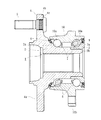
こうした問題を解決したものとして、本出願人は図5に示すような車輪用軸受装置を提案している。この車輪用軸受装置は、外周に懸架装置(図示せず)に取り付けられる車体取付フランジ51bを一体に有し、内周に複列の外側転走面51a、51aが形成された外方部材51と、一端部に車輪(図示せず)を取り付けるための車輪取付フランジ52を一体に有し、外周に前記複列の外側転走面51a、51aに対向する一方の内側転走面53aと、この内側転走面53aから軸方向に延びる円筒状の小径段部53bが形成されたハブ輪53、およびこのハブ輪53の小径段部53bに圧入され、外周に前記複列の外側転走面51a、51aに対向する他方の内側転走面54aが形成された内輪54とからなる内方部材55と、この内方部材55と外方部材51との間に転動自在に介装された複列の転動体(ボール)56、56と、外方部材51の両端部に装着されたシール57、57とからなる。
As a solution to these problems, the present applicant has proposed a wheel bearing device as shown in FIG. This wheel bearing device is integrally provided with a vehicle body mounting flange 51b attached to a suspension device (not shown) on the outer periphery, and an
車輪取付フランジ52には、周方向等配に車輪を固定するためのハブボルト58が植設され、車輪取付フランジ52のアウトボード側にブレーキロータ59を支持する円筒状のブレーキパイロット部60と、このブレーキパイロット部60からさらにアウトボード側にホイールパイロット部61が一体に形成されている。そして、フランジ側面52aにブレーキロータ59がボルト62によって固定される。
The
ここで、固定部材となる外方部材51を基準に回転駆動させた状態で、ブレーキロータ59を取り付けるフランジ側面52aの面振れが規格値内、例えば50μm以下に規制されているので、信頼性が高く、ブレーキロータ59を取り付ける時、または後に、面倒なブレーキロータ59の振れ調整を行なう必要がなくなる。
こうした従来の車輪用軸受装置は、ブレーキロータ59を取り付けるフランジ側面52aの面振れが規格値内に規制されているので、信頼性が高く、ブレーキロータ59を取り付ける時、または後に、面倒なブレーキロータ59の振れ調整を行なう必要がない。しかし、自動車のNVH対策に対する要求は益々厳しくなり、この面振れの規制をするだけではこの厳しくなってきているNVHを抑制することは難しくなってきている。一方、通常車輪自体はそれを装着する前、所定の規定値内にホイールバランスを調整してアンバランスを抑制しているが、この種の車軸においてはバランス調整は実施されていない。
Such a conventional wheel bearing device has high reliability because the surface runout of the
車軸においては、バランス(釣合い良さ)の等級として一応大まかな推奨値(JIS B 0905−1992)が提案されている。これは上限値であって、この種の振動をはじめ、複雑な要因によって誘発されるNVHを抑制するだけの効果があるか否かの検証はなされていない。このような状況において、製造現場でアンバランスを調整することは未だ実施されていないのが現状である。この車軸のアンバランスが大きくなると、NVH及び操縦安定性に悪影響を及ぼすことが考えられる。増してや、除肉がなされ軽量化が進む傾向にある車輪用軸受装置にあってはそのアンバランスは無視できない。 For axles, a rough recommended value (JIS B 0905-1992) has been proposed as a balance (goodness of balance) grade. This is an upper limit value, and it has not been verified whether or not there is an effect to suppress NVH induced by complicated factors including this kind of vibration. Under such circumstances, the current situation is that adjustment of imbalance at the manufacturing site has not yet been carried out. If this axle imbalance becomes large, it is considered that NVH and steering stability are adversely affected. In addition, the unbalance cannot be ignored in a wheel bearing device that tends to be thinned and lightened.
本発明は、このような事情に鑑みてなされたもので、ハブ輪の軽量・コンパクト化を図ると共に、車両のNVHを抑制し、かつ操縦安定性を向上させた車輪用軸受装置を提供することを目的としている。 The present invention has been made in view of such circumstances, and provides a wheel bearing device in which the hub wheel is reduced in weight and size, the NVH of the vehicle is suppressed, and the steering stability is improved. It is an object.
係る目的を達成すべく、本発明のうち請求項1に記載の発明は、内周に複列の外側転走面が形成された外方部材と、外周に前記複列の外側転走面に対向する複列の内側転走面が形成された内方部材と、この内方部材および前記外方部材のそれぞれの転走面間に転動自在に収容された複列の転動体とを備え、前記内方部材または外方部材のいずれか一方に車輪取付フランジが一体に設けられると共に、この車輪取付フランジの円周等配位置にハブボルトが植設された車輪用軸受装置において、前記ハブボルトが予め質量の異なる複数のグループに分類され、前記車輪取付フランジの静アンバランス量に対応して選択されて取り付けられている構成を採用した。
In order to achieve such an object, the invention according to
このように、ハブボルトが予め質量の異なる複数のグループに分類され、車輪取付フランジの静アンバランス量に対応して選択して圧入されることにより、車輪取付フランジの静アンバランス量が所定の管理されているので、調整作業が簡素化でき、低コスト化が図れると共に、車両のNVHを抑制し、かつ操縦安定性を向上させた車輪用軸受装置を提供することができる。 As described above, the hub bolts are classified into a plurality of groups having different masses in advance, and selected according to the static unbalance amount of the wheel mounting flange and press-fitted, so that the static unbalance amount of the wheel mounting flange is controlled in a predetermined manner. Therefore, the adjustment work can be simplified, the cost can be reduced, the vehicle wheel NVH can be suppressed, and the steering stability can be improved.
また、請求項2に記載の発明は、前記車輪取付フランジの静アンバランス量の規格値が450g・mmとされているので、種々の構造の車輪用軸受装置において、NVHを抑制し、かつ操縦安定性を向上させる。
In the invention according to
また、請求項3に記載の発明は、前記静アンバランス量が、前記車輪取付フランジの外径部または前記ハブボルトのボルト座面、あるいは両方の切削によって調整されているので、車輪取付フランジ自体の強度・剛性を損なうことなく、必要最小限の修正量で済んで効果的である。 According to a third aspect of the present invention, since the static unbalance amount is adjusted by cutting the outer diameter portion of the wheel mounting flange, the bolt seat surface of the hub bolt, or both, the wheel mounting flange itself It is effective to use the minimum necessary correction amount without losing strength and rigidity.
また、請求項4に記載の発明は、固定部材となる前記内方部材または外方部材を基準に回転駆動させた状態で、ブレーキロータを取り付ける前記車輪取付フランジのフランジ側面の面振れが規格値内に規制されているので、車両のNVHを抑制すると共に、ブレーキの偏摩耗を防止することができる。 In the invention according to claim 4, the runout on the flange side surface of the wheel mounting flange to which the brake rotor is mounted is a standard value in a state where the inner member or the outer member serving as the fixing member is rotationally driven with reference to the reference member. Therefore, the NVH of the vehicle can be suppressed and uneven wear of the brake can be prevented.
また、請求項5に記載の発明は、前記内方部材が、一端部に車輪取付フランジを一体に有し、外周に小径段部が形成されたハブ輪、およびこのハブ輪の小径段部に圧入され、外周に前記複列の外側転走面に対向する内側転走面が形成された少なくとも一つの内輪とを備え、前記車輪取付フランジが、円周方向複数に分割され、それぞれの車輪取付フランジに前記ハブボルトが圧入されるボルト挿通孔が穿設されると共に、前記車輪取付フランジは、前記ボルト挿通孔の近傍を除く部分を切欠いて、各ボルト挿通孔の形成部分と略同じ幅でもって環状の基部から放射状に突出するように形成され、そのインボード側の側面に、その基部に向って漸次肉厚になるようにリブが形成されているので、ハブ輪の剛性を損なうことなく可及的に軽量化を達成することができる。 According to a fifth aspect of the present invention, the inner member includes a hub wheel integrally having a wheel mounting flange at one end and a small-diameter step portion formed on the outer periphery, and a small-diameter step portion of the hub ring. At least one inner ring that is press-fitted and formed on the outer periphery with an inner rolling surface facing the double-row outer rolling surface, and the wheel mounting flange is divided into a plurality of circumferential directions, each wheel mounting A bolt insertion hole into which the hub bolt is press-fitted is formed in the flange, and the wheel mounting flange is cut out at a portion other than the vicinity of the bolt insertion hole and has substantially the same width as the formation portion of each bolt insertion hole. It is formed so as to protrude radially from the annular base, and ribs are formed on the side surface on the inboard side so as to gradually increase in thickness toward the base, so that it is possible without impairing the rigidity of the hub wheel. As light as possible It can be formed.
また、請求項6に記載の発明は、前記外方部材が、外周に懸架装置を構成するナックルに取り付けられ、円周方向複数に分割された車体取付フランジを一体に有し、それぞれの車体取付フランジの外周部にボルト挿通孔が穿設されると共に、前記車体取付フランジが、前記ボルト挿通孔の近傍を除く部分を切欠いて、各ボルト挿通孔の形成部分と略同じ幅でもって環状の基部から放射状に突出するように形成されているので、外方部材の剛性を損なうことなく可及的に軽量化を達成することができる。 According to a sixth aspect of the present invention, the outer member is integrally attached to a knuckle that constitutes a suspension device on the outer periphery, and has a vehicle body mounting flange that is divided into a plurality of circumferential directions. A bolt insertion hole is formed in the outer peripheral portion of the flange, and the vehicle body mounting flange is cut out at a portion other than the vicinity of the bolt insertion hole, and has an annular base portion having substantially the same width as the formation portion of each bolt insertion hole. Therefore, the weight can be reduced as much as possible without impairing the rigidity of the outer member.
本発明に係る車輪用軸受装置は、内周に複列の外側転走面が形成された外方部材と、外周に前記複列の外側転走面に対向する複列の内側転走面が形成された内方部材と、この内方部材および前記外方部材のそれぞれの転走面間に転動自在に収容された複列の転動体とを備え、前記内方部材または外方部材のいずれか一方に車輪取付フランジが一体に設けられると共に、この車輪取付フランジの円周等配位置にハブボルトが植設された車輪用軸受装置において、前記ハブボルトが予め質量の異なる複数のグループに分類され、前記車輪取付フランジの静アンバランス量に対応して選択されて取り付けられているので、調整作業が簡素化でき、低コスト化が図れると共に、車両のNVHを抑制し、かつ操縦安定性を向上させた車輪用軸受装置を提供することができる。 The wheel bearing device according to the present invention includes an outer member having a double row outer raceway formed on the inner periphery, and a double row inner raceway facing the outer row raceway on the outer periphery. An inner member formed, and a double row rolling element that is rotatably accommodated between the rolling surfaces of the inner member and the outer member, the inner member or the outer member In the wheel bearing device in which the wheel mounting flange is integrally provided on one of the wheels and the hub bolt is implanted at the circumferentially equidistant position of the wheel mounting flange, the hub bolts are classified into a plurality of groups having different masses in advance. Since the wheel mounting flange is selected and mounted according to the static unbalance amount, the adjustment work can be simplified, the cost can be reduced, the vehicle NVH can be suppressed, and the driving stability can be improved. Proposed wheel bearing device It can be.
内周に複列の外側転走面が形成された外方部材と、一端部に車輪取付フランジを一体に有し、外周に前記複列の外側転走面に対向する一方の内側転走面と、この内側転走面から軸方向に延びる円筒状の小径段部が形成されたハブ輪、およびこのハブ輪の小径段部に圧入され、前記複列の外側転走面に対向する他方の内側転走面が形成された内輪とからなる内方部材と、この内方部材と前記外方部材の両転走面間に転動自在に収容された複列の転動体とを備え、前記車輪取付フランジの円周等配位置にハブボルトが植設された車輪用軸受装置において、前記ハブボルトが予め質量の異なる複数のグループに分類され、前記車輪取付フランジの静アンバランス量に対応して選択されることにより当該車輪取付フランジの静アンバランス量が所定の規格値内に規制されている。 An outer member having a double row outer raceway formed on the inner circumference, and a wheel mounting flange at one end, and one inner raceway facing the double row outer raceway on the outer circumference. A hub wheel formed with a cylindrical small-diameter step portion extending in the axial direction from the inner rolling surface, and the other of the hub wheel pressed into the small-diameter step portion of the hub wheel and facing the outer rolling surface of the double row An inner member composed of an inner ring formed with an inner rolling surface, and a double row rolling element that is slidably accommodated between both rolling surfaces of the inner member and the outer member, In a wheel bearing device in which hub bolts are implanted at circumferentially equidistant positions on the wheel mounting flange, the hub bolts are classified into a plurality of groups having different masses in advance, and selected according to the static unbalance amount of the wheel mounting flange. The static unbalance amount of the wheel mounting flange is It is regulated within the rated value.
以下、本発明の実施の形態を図面に基いて詳細に説明する。
図1は、本発明に係る車輪用軸受装置の第1の実施形態を示す縦断面図である。なお、以下の説明では、車両に組み付けた状態で車両の外側寄りとなる側をアウトボード側(図面左側)、中央寄り側をインボード側(図面右側)という。
Hereinafter, embodiments of the present invention will be described in detail with reference to the drawings.
FIG. 1 is a longitudinal sectional view showing a first embodiment of a wheel bearing device according to the present invention. In the following description, the side closer to the outer side of the vehicle when assembled to the vehicle is referred to as the outboard side (left side in the drawing), and the side closer to the center is referred to as the inboard side (right side in the drawing).
この車輪用軸受装置は、内方部材1と外方部材10、および両部材1、10間に転動自在に収容された複列の転動体(ボール)6、6とを備えている。内方部材1は、ハブ輪2と、このハブ輪2に外嵌された別体の内輪3とからなる。ハブ輪2は、アウトボード側の端部に車輪(図示せず)を取り付けるための車輪取付フランジ4を一体に有し、この車輪取付フランジ4の円周等配位置には車輪を固定するためのハブボルト5が植設されている。また、ハブ輪2の外周には内側転走面2aと、この内側転走面2aから軸方向に延びる小径段部2bが形成されている。そして、外周に内側転走面3aが形成された内輪3がこの小径段部2bに圧入されている。
The wheel bearing device includes an
外方部材10は、外周に車体(図示せず)に取り付けるための車体取付フランジ10bを一体に有し、内周には複列の外側転走面10a、10aが形成されている。そして、それぞれの転走面10a、2aと10a、3a間に複列の転動体6、6が収容され、保持器7、7によりこれら複列の転動体6、6が転動自在に保持されている。また、外方部材10の端部にはシール装置8、9が装着され、軸受内部に封入した潤滑グリースの漏洩を防止すると共に、外部からの雨水やダスト等が軸受内部に侵入するのを防止している。
The
ここでは、ハブ輪2の外周に直接内側転走面2aが形成された第3世代と呼称される車輪用軸受装置を例示したが、本発明に係る車輪用軸受装置はこうした構造に限定されず、例えば、図示はしないが、ハブ輪の小径段部に一対の内輪を圧入した、第1世代あるいは第2世代構造であっても良い。なお、転動体6、6をボールとした複列アンギュラ玉軸受を例示したが、これに限らず転動体に円すいころを使用した複列円すいころ軸受であっても良い。
Here, the wheel bearing device referred to as the third generation in which the
ハブ輪2は、S53C等の炭素0.40〜0.80重量%を含む中炭素鋼で形成され、アウトボード側の内側転走面2aをはじめ、アウトボード側のシール装置8が摺接するシールランド部、および小径段部2bに亙り高周波焼入れによって表面硬さを58〜64HRCの範囲に硬化処理されている。また、外方部材10は、S53C等の炭素0.40〜0.80重量%を含む中炭素鋼で形成され、複列の外側転走面10a、10aをはじめ、シール装置8、9が嵌合する端部内径面に亙って高周波焼入れによって表面硬さを58〜64HRCの範囲に硬化処理されている。
The
本実施形態では、従来と同様、ハブ輪2の鍛造工程後に車輪取付フランジ4のフランジ側面4aが切削により仕上げ加工され、固定部材となる外方部材10を基準に回転駆動させた状態で、ブレーキロータ(図示せず)を取り付けるフランジ側面4aの面振れが規格値内、例えば50μm以下に規制されている。さらに、車輪取付フランジ4のバランス調整が実施されている。
In the present embodiment, the
この車輪取付フランジ4のバランス調整は、ハブ輪2および内輪3のみで行なっても良いが、車輪用軸受装置を組み立て、外方部材10を基準に回転駆動させた状態で、車輪取付フランジ4のアンバランス位置および静アンバランス量を実測することによって行なわれるのが好ましい。また、ハブボルト5は、予め質量の異なる複数のグループに分類されている。そして、前述した実測値に対応して複数のグループのうち、適宜所定の質量範囲のグループを選択し、車輪取付フランジ4にハブボルト5を圧入することにより、車輪取付フランジ4の静アンバランス量が所定の規格値内に規制されている。こうしたマッチング作業による調整作業は、オンライン上で行なうことができ、作業自体が簡素化できて低コスト化が図れると共に、車両のNVHを抑制し、かつ操縦安定性を向上させた車輪用軸受装置を提供することができる。
The balance adjustment of the wheel mounting flange 4 may be performed only by the
ここで、各グループの質量範囲を狭く設定し、分類するグループ数を増やすことにより、バランス調整をより高精度化することも可能であるが、マッチング作業が煩雑化し、作業性が低下する恐れがあるので、グループ数は3〜5の範囲が好ましい。さらに、バランス調整をより高精度化するため、こうしたマッチング作業後に、車輪取付フランジ4の外径部4bあるいはハブボルト5が圧入される円形のボルト座面4cを切削により追加工しても良い。
Here, it is possible to make the balance adjustment more precise by setting the mass range of each group narrow and increasing the number of groups to be classified, but there is a risk that the matching work becomes complicated and the workability is reduced. Therefore, the number of groups is preferably in the range of 3-5. Furthermore, in order to make the balance adjustment more accurate, after such a matching operation, the circular
また、マッチング作業前に、予めハブボルト5が圧入される円形のボルト座面4cを切削により加工することにより、鍛造後のアンバランスをある程度解消し、マッチング作業時に、車輪取付フランジ4の外径部4bを切削により追加工するようにしても良い。この外径部4bの切削加工は、ハブボルト5の圧入後であっても可能である。なお、アンバランス修正部は、車輪取付フランジ4のどの部位でも可能であるが、必要最小限の修正量で済む外径部4bあるいはこの外径部4bとハブボルト5のボルト座面4cが効果的である。これら外径部4bあるいはハブボルト5のボルト座面4cであれば、車輪取付フランジ4自体の強度・剛性を損なうことなく、また、ボルト座面4cの切削加工により、面粗さが向上してハブボルト5の圧入精度の向上やスリップトルクを増大させる効果も期待できる。
Further, by machining the circular
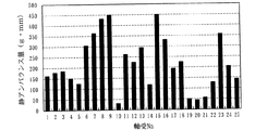
図2は、本出願人が実測した種々の構造における車輪取付フランジ4の静アンバランス量を示すグラフである。なお、軸受NO.1乃至NO.20は、第2世代構造、軸受NO.21乃至NO.25は、第3世代構造における静アンバランス量を示している。このグラフから解るように、軸受構造に係らず、車輪取付フランジ4の質量、転動体6の位置、および重心位置の違いによって静アンバランス量が25〜450g・mmの範囲に大きく推移している。ここで、静アンバランスとは、釣合いの状態にあるロータ上に余分に(または不足に)存在する質量のことを言う。
FIG. 2 is a graph showing the static unbalance amount of the wheel mounting flange 4 in various structures actually measured by the present applicant. Bearing NO. 1 to NO. 20 is a second generation structure, bearing NO. 21 to NO. Reference numeral 25 denotes a static unbalance amount in the third generation structure. As can be seen from this graph, regardless of the bearing structure, the static unbalance amount has greatly changed in the range of 25 to 450 g · mm depending on the mass of the wheel mounting flange 4, the position of the rolling
一方、前述したJISにおいて、許容残留不釣合いUは、U=e×m×10−3で示されている。ここで、eは許容不釣合い(μm)、mは車輪取付フランジ4の質量(g)を言い、許容不釣合いeは実用最高回転数n(r/min.)から算出される。因みに、実用最高回転数nを1600r/min.とし、車輪取付フランジ4の質量mを2000gとした場合、自動車用車軸の釣合い良さの等級G40では、その許容残留不釣合いUの計算値は略560g・mmとなる。実際には、この種の車輪用軸受装置の車輪取付フランジ4にはブレーキロータが取り付けられるため、さらに許容残留不釣合いは大きくなることが予想できる。したがって、ブレーキロータが装着された状態で許容残留不釣合いが、少なくとも560g・mm以下になるよう、本実施形態では、車輪取付フランジ4の静アンバランス量がその略80%の450g・mm以下に規制されている。 On the other hand, in the JIS described above, the allowable residual unbalance U is indicated by U = e × m × 10 −3 . Here, e is the allowable unbalance (μm), m is the mass (g) of the wheel mounting flange 4, and the allowable unbalance e is calculated from the practical maximum rotational speed n (r / min.). Incidentally, the practical maximum rotational speed n is set to 1600 r / min. When the mass m of the wheel mounting flange 4 is 2000 g, the calculated value of the allowable residual unbalance U is approximately 560 g · mm in the balance grade G40 of the axle for automobiles. Actually, since the brake rotor is attached to the wheel mounting flange 4 of this type of wheel bearing device, it can be expected that the allowable residual unbalance will be further increased. Therefore, in this embodiment, the static unbalance amount of the wheel mounting flange 4 is approximately 80% of 450 g · mm or less so that the allowable residual imbalance is at least 560 g · mm or less with the brake rotor mounted. It is regulated.
因みに、ホイールバランスを調整することにより、NVHおよび操縦安定性は向上すると言われ、一般乗用車用として用いられているホイール径14インチ(半径略180mm)でのリム上5g(バランスウェイトの最小単位)のアンバランス量は略900g・mmとなる。本実施形態では、車輪取付フランジ4の静アンバランス量がこのホイールバランスの調整可能域の略1/2に規制されることになるため、NVHおよび操縦安定性に対して充分な効果を発揮する。 Incidentally, by adjusting the wheel balance, NVH and steering stability are said to be improved, and 5g (minimum unit of balance weight) on the rim with a wheel diameter of 14 inches (radius approximately 180mm) used for ordinary passenger cars. The unbalance amount is about 900 g · mm. In this embodiment, since the amount of static unbalance of the wheel mounting flange 4 is regulated to approximately ½ of the adjustable range of the wheel balance, a sufficient effect is exhibited for NVH and steering stability. .
本実施形態では、軽量・コンパクト化を図ると共に、固定部材となる外方部材10を基準に回転駆動させた状態で、ブレーキロータを取り付けるフランジ側面4aの面振れが規格値内に規制され、さらに、ハブボルト5が予め質量の異なる複数のグループに分類され、車輪取付フランジ4の静アンバランス量に対応して選択されることにより、車輪取付フランジ4の静アンバランス量が所定の規格値内に規制されているので、車両のNVHの抑制は言うまでもなく操縦安定性を向上させた車輪用軸受装置を提供することができる。
In the present embodiment, the surface runout of the
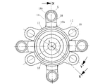
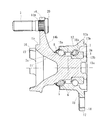
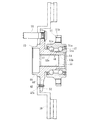
図3は、本発明に係る車輪用軸受装置の第2の実施形態を示す正面図、図4は図3の縦断面図である。この実施形態はハブ輪と外方部材が除肉されたもので、その他前述した実施形態と同一部品同一部位には同じ符号を付してその詳細な説明を省略する。なお、図4において、ハブ輪は図3のX−O−X線に沿った断面、外方部材は図3のX−O−Y線に沿った断面をそれぞれ示している。 FIG. 3 is a front view showing a second embodiment of the wheel bearing device according to the present invention, and FIG. 4 is a longitudinal sectional view of FIG. In this embodiment, the hub wheel and the outer member are thinned, and the same components and parts as those in the above-described embodiment are denoted by the same reference numerals, and detailed description thereof is omitted. In FIG. 4, the hub wheel shows a cross section taken along line XX in FIG. 3, and the outer member shows a cross section taken along line XX in FIG. 3.
この車輪用軸受装置は、従動輪を回転自在に支承する車輪用軸受装置であって、内方部材11と外方部材12、および両部材11、12間に転動自在に収容された複列の転動体(ボール)6、6とを備えている。ここで、内方部材11は、ハブ輪13と、このハブ輪13に圧入された内輪3とを指す。
This wheel bearing device is a wheel bearing device that rotatably supports a driven wheel, and is a double row accommodated in an freely rotatable manner between the
ハブ輪13は、外周のアウトボード側の端部に円周方向複数(4つ)に分割された車輪取付フランジ14を一体に有し、それぞれの車輪取付フランジ14の外周部には車輪を締結するためのハブボルト5が植設されている。車輪取付フランジ14は、ボルト挿通孔14aの近傍を除く部分を切欠いて、各ボルト挿通孔14aの形成部分と略同じ幅でもって環状の基部、すなわち、後述するブレーキパイロット部15から放射状に突出するように形成されている。さらに、車輪取付フランジ14のインボード側の側面には、その基部に向って漸次肉厚になるようにリブ14bが形成されている。これにより、ハブ輪13の剛性を損なうことなく軽量化を達成することができる。
The
なお、本実施形態では、車輪取付フランジ14が、ボルト挿通孔14aの近傍を除く部分を切欠いて、各ボルト挿通孔14aの形成部分と略同じ幅でもって、その環状の基部から放射状に突出するように形成されたものを例示したが、これに限らず、図示はしないが、ボルト挿通孔の周辺を避けてボルト挿通孔間に、このボルト挿通孔のピッチ円直径より内径側まで深くR形状の切欠きが形成された車輪取付フランジのようなものであっても良い。
In the present embodiment, the
また、ハブ輪13における車輪取付フランジ14のインボード側の外周には内側転走面2aと、この内側転走面2aから軸方向に延びる円筒状の小径段部13aが形成され、この小径段部13aに内輪3が所定のシメシロを介して圧入されている。そして、小径段部13aの端部を径方向外方に塑性変形させて加締部13bが形成されている。この加締部13bにより、内輪3はハブ輪13に対して軸方向に固定され、所謂セルフリテイン構造を構成している。これにより、従来のようにナット等で強固に緊締して予圧量を管理する必要がないため、軽量・コンパクト化を図ることができると共に、ハブ輪13の強度・耐久性を向上させ、かつ長期間その予圧量を維持することができる。
Further, an
ハブ輪13は、S53C等の炭素0.40〜0.80wt%を含む中炭素鋼で形成され、車輪取付フランジ14のインボード側の基部から内側転走面2aおよび小径段部13aに亙り高周波焼入れによって表面硬さを58〜64HRCの範囲に硬化処理されている。これにより、車輪取付フランジ14の基部は、車輪取付フランジ14に負荷される回転曲げ荷重に対して充分な機械的強度を有し、ハブ輪13の耐久性が一層向上する。なお、加締部13bは、鍛造後の素材表面硬さ25HRC以下の未焼入れ部としている。これにより、加締部13bを塑性変形させる時の加工性が向上すると共に、加工時におけるクラック等の発生を防止してその品質の信頼性が向上する。
The
ハブ輪13の車輪取付フランジ14の基部には、アウトボード側に延びる円筒状のブレーキパイロット部15が形成され、ブレーキロータ(図示せず)の内径面を案内している。また、このブレーキパイロット部15からさらにアウトボード側に延びるホイールパイロット部16が形成されている。このホイールパイロット部16は、ブレーキロータに重ねて装着されるホイールハブ(図示せず)の内径面を案内するもので、前記ブレーキパイロット部15よりも僅かに小径に形成されている。そして、その円周方向の複数箇所に切欠きが設けられ、断続して突片状に形成されている。ここでは、この断続したホイールパイロット部16は、複数に分割された車輪取付フランジ14間に形成されている。これにより、ハブ輪13の剛性を低下させることなく可及的に軽量化を図ることができる。
A cylindrical
一方、外方部材12は、外周に懸架装置を構成するナックル(図示せず)に取り付けられる円周方向複数(4つ)に分割された車体取付フランジ17を一体に有し、それぞれの車体取付フランジ17の外周部にボルト挿通孔18が穿設されている。この車体取付フランジ17は、ボルト挿通孔18の近傍を除く部分を切欠いて、各ボルト挿通孔18の形成部分と略同じ幅でもって環状の基部12aから放射状に突出するように形成されている。そして、ボルト挿通孔18に貫通するナックルボルト(図示せず)によりナックルに固定される。さらに、外方部材12のインボード側の端部には、前記車体取付フランジ17から軸方向に延びる円筒状のナックルパイロット部12bが形成され、このナックルパイロット部12bの外径面にナックルが嵌合される。
On the other hand, the
外方部材12のアウトボード側の端部にはシール装置8が装着され、外方部材12と内方部材11との環状空間を密封している。一方、外方部材12のインボード側の端部には、カップ状のシールキャップ(図示せず)が装着され、外方部材12の開口部を閉塞している。これらシール装置8およびシールキャップにより、軸受内部に封入された潤滑グリースの外部への漏洩と、外部から雨水やダスト等が軸受内部に侵入するのを防止している。
A
また、外方部材12は、ハブ輪13と同様、S53C等の炭素0.40〜0.80wt%を含む中炭素鋼で形成され、複列の外側転走面10a、10aに高周波焼入れによって表面硬さを58〜64HRCの範囲に硬化処理されている。
Further, the
このように、外方部材12は、外周に円周方向複数に分割された車体取付フランジ15を一体に有し、この車体取付フランジ17の外周部に複数のボルト挿通孔18が穿設されると共に、このボルト挿通孔18の近傍を除く部分を切欠いて、各ボルト挿通孔18の形成部分と略同じ幅でもって環状の基部12aから放射状に突出するように形成されているので、外方部材12の剛性を損なうことなく可及的に軽量化を達成することができる。なお、前記ナックルパイロット部12bが、その円周方向の複数箇所に切欠きが設けられ、断続して突片状に形成されていても良い。これにより、外方部材12の軽量化を一層図ることができる。
Thus, the
また、ハブ輪13の車輪取付フランジ14が、ボルト挿通孔14aの近傍を除く部分を切欠いて、各ボルト挿通孔14aの形成部分だけが環状の基部から外径側に略同じ幅でもって突出するように形成されているので、外方部材12をナックルに締結する際に、この車輪取付フランジ14に邪魔されることなく、工具にて容易にナックルボルトを締結することができ、組立作業を簡便化することができる。
Further, the
本実施形態では、ハブ輪13および外方部材12は前述した実施形態よりも一段と除肉され、その車輪取付フランジ14が複数に分割されると共に、その肉厚自体も薄く形成されているので、車輪取付フランジ14に質量バランスが崩れる恐れがある。しかしながら、車輪取付フランジ14の側面に、バランス修正面となる環状のボルト座面20がそれぞれ切削により形成されると共に、ハブボルト5が予め質量の異なる複数のグループに分類され、車輪取付フランジ14の静アンバランス量に対応して選択されることにより、車輪取付フランジ14の静アンバランス量が所定の規格値内に規制されている。これにより、軽量・コンパクト化を図ると共に、車両のNVHを抑制し、かつ操縦安定性を向上させた車輪用軸受装置を提供することができる。
In the present embodiment, the
以上、本発明の実施の形態について説明を行ったが、本発明はこうした実施の形態に何等限定されるものではなく、あくまで例示であって、本発明の要旨を逸脱しない範囲内において、さらに種々なる形態で実施し得ることは勿論のことであり、本発明の範囲は、特許請求の範囲の記載によって示され、さらに特許請求の範囲に記載の均等の意味、および範囲内のすべての変更を含む。 The embodiment of the present invention has been described above, but the present invention is not limited to such an embodiment, and is merely an example, and various modifications can be made without departing from the scope of the present invention. Of course, the scope of the present invention is indicated by the description of the scope of claims, and further, the equivalent meanings described in the scope of claims and all modifications within the scope of the scope of the present invention are included. Including.
本発明に係る車輪用軸受装置は、駆動輪用あるいは従動輪用の第1世代乃至第3世代の車輪用軸受装置に適用できる。 The wheel bearing device according to the present invention can be applied to first-generation to third-generation wheel bearing devices for driving wheels or driven wheels.
1、11・・・・・・・内方部材
2、13・・・・・・・ハブ輪
2a、3a・・・・・・内側転走面
2b、13a・・・・・小径段部
3・・・・・・・・・・内輪
4、14・・・・・・・車輪取付フランジ
4a・・・・・・・・・フランジ側面
4b・・・・・・・・・外径部
4c、19、20・・・ボルト座面
5・・・・・・・・・・ハブボルト
6・・・・・・・・・・転動体
7・・・・・・・・・・保持器
8・・・・・・・・・・アウトボード側のシール装置
9・・・・・・・・・・インボード側のシール装置
10、12・・・・・・外方部材
10a・・・・・・・・外側転走面
10b、17・・・・・車体取付フランジ
14a、18・・・・・ボルト挿通孔
14b・・・・・・・・リブ
15・・・・・・・・・ブレーキパイロット部
16・・・・・・・・・ホイールパイロット部
51・・・・・・・・・外方部材
51a・・・・・・・・外側転走面
51b・・・・・・・・車体取付フランジ
52・・・・・・・・・車輪取付フランジ
52a・・・・・・・・フランジ側面
53・・・・・・・・・ハブ輪
53a、54a・・・・内側転走面
53b・・・・・・・・小径段部
54・・・・・・・・・内輪
55・・・・・・・・・内方部材
56・・・・・・・・・転動体
57・・・・・・・・・シール
58・・・・・・・・・ハブボルト
59・・・・・・・・・ブレーキロータ
60・・・・・・・・・ブレーキパイロット部
61・・・・・・・・・ホイールパイロット部
62・・・・・・・・・ボルト
e・・・・・・・・・・許容不釣合い
m・・・・・・・・・・車輪取付フランジの質量
n・・・・・・・・・・実用最高回転数
U・・・・・・・・・・許容残留不釣合い
1, 11 ······
Claims (6)
外周に前記複列の外側転走面に対向する複列の内側転走面が形成された内方部材と、
この内方部材および前記外方部材のそれぞれの転走面間に転動自在に収容された複列の転動体とを備え、
前記内方部材または外方部材のいずれか一方に車輪取付フランジが一体に設けられると共に、この車輪取付フランジの円周等配位置にハブボルトが植設された車輪用軸受装置において、
前記ハブボルトが予め質量の異なる複数のグループに分類され、前記車輪取付フランジの静アンバランス量に対応して選択されて取り付けられていることを特徴とする車輪用軸受装置。 An outer member having a double row outer raceway formed on the inner periphery;
An inner member in which a double row inner rolling surface facing the outer row rolling surface of the double row is formed on the outer periphery;
A double-row rolling element housed movably between the rolling surfaces of the inner member and the outer member;
In the wheel bearing device in which either one of the inner member and the outer member is integrally provided with a wheel mounting flange, and hub bolts are implanted at circumferentially equidistant positions of the wheel mounting flange.
The wheel bearing device according to claim 1, wherein the hub bolts are classified into a plurality of groups having different masses in advance, and are selected and mounted in accordance with a static unbalance amount of the wheel mounting flange.
Priority Applications (1)
| Application Number | Priority Date | Filing Date | Title |
|---|---|---|---|
| JP2004154309A JP2005335455A (en) | 2004-05-25 | 2004-05-25 | Bearing device for wheel |
Applications Claiming Priority (1)
| Application Number | Priority Date | Filing Date | Title |
|---|---|---|---|
| JP2004154309A JP2005335455A (en) | 2004-05-25 | 2004-05-25 | Bearing device for wheel |
Publications (1)
| Publication Number | Publication Date |
|---|---|
| JP2005335455A true JP2005335455A (en) | 2005-12-08 |
Family
ID=35489504
Family Applications (1)
| Application Number | Title | Priority Date | Filing Date |
|---|---|---|---|
| JP2004154309A Pending JP2005335455A (en) | 2004-05-25 | 2004-05-25 | Bearing device for wheel |
Country Status (1)
| Country | Link |
|---|---|
| JP (1) | JP2005335455A (en) |
Cited By (4)
| Publication number | Priority date | Publication date | Assignee | Title |
|---|---|---|---|---|
| JP2013223869A (en) * | 2012-04-20 | 2013-10-31 | Ntn Corp | Wheel bearing device and method for manufacturing the same |
| CN104455140A (en) * | 2014-11-14 | 2015-03-25 | 孙欣 | Damper for vehicle suspension |
| JP2015081542A (en) * | 2013-10-22 | 2015-04-27 | Ntn株式会社 | Turbocharger bearing device and turbocharger bearing device manufacturing method |
| US10443683B2 (en) | 2017-09-14 | 2019-10-15 | Fanuc Corporation | Bearing and eccentricity correction method |
-
2004
- 2004-05-25 JP JP2004154309A patent/JP2005335455A/en active Pending
Cited By (8)
| Publication number | Priority date | Publication date | Assignee | Title |
|---|---|---|---|---|
| JP2013223869A (en) * | 2012-04-20 | 2013-10-31 | Ntn Corp | Wheel bearing device and method for manufacturing the same |
| US9573419B2 (en) | 2012-04-20 | 2017-02-21 | Ntn Corporation | Wheel bearing apparatus and its manufacturing method |
| JP2015081542A (en) * | 2013-10-22 | 2015-04-27 | Ntn株式会社 | Turbocharger bearing device and turbocharger bearing device manufacturing method |
| WO2015060304A1 (en) * | 2013-10-22 | 2015-04-30 | Ntn株式会社 | Bearing device for turbocharger, and method for manufacturing bearing device for turbocharger |
| CN105593489A (en) * | 2013-10-22 | 2016-05-18 | Ntn株式会社 | Bearing device for turbocharger, and method for manufacturing bearing device for turbocharger |
| US9784315B2 (en) | 2013-10-22 | 2017-10-10 | Ntn Corporation | Bearing assembly for a turbocharger, and a method for manufacturing a bearing assembly for a turbocharger |
| CN104455140A (en) * | 2014-11-14 | 2015-03-25 | 孙欣 | Damper for vehicle suspension |
| US10443683B2 (en) | 2017-09-14 | 2019-10-15 | Fanuc Corporation | Bearing and eccentricity correction method |
Similar Documents
| Publication | Publication Date | Title |
|---|---|---|
| US7942585B2 (en) | Wheel bearing apparatus for a vehicle | |
| JP4484104B2 (en) | Wheel bearing device | |
| JP6587851B2 (en) | Wheel bearing device | |
| JP5134356B2 (en) | Wheel bearing device | |
| JP5030082B2 (en) | Wheel bearing device | |
| JP5057553B2 (en) | Wheel bearing device | |
| JP6366233B2 (en) | Wheel bearing device | |
| JP2006036020A (en) | Bearing device for drive wheel | |
| JP2010089664A (en) | Bearing device for wheel | |
| JP2006036112A (en) | Bearing device for wheel | |
| JP4844967B2 (en) | Wheel bearing device | |
| JP4439334B2 (en) | Wheel bearing device | |
| JP2005335455A (en) | Bearing device for wheel | |
| JP2003154801A (en) | Bearing device for wheel | |
| JP2000185507A (en) | Constant velocity joint | |
| JP2006007791A (en) | Bearing unit for wheel | |
| JP4993342B2 (en) | Wheel bearing device | |
| JP2007176485A (en) | Bearing device for wheel | |
| JP2004338584A (en) | Manufacturing method of bearing unit for driving wheel and drive unit for wheel | |
| JP5116131B2 (en) | Drive wheel bearing device | |
| JP2003175702A (en) | Bearing device for driving wheel | |
| JP2006007910A (en) | Bearing device for wheel | |
| JP2005337311A (en) | Bearing device for wheel | |
| JP4969899B2 (en) | Wheel bearing device | |
| JP2005289147A (en) | Bearing device for wheel |