JP2005297853A - Trailer - Google Patents
Trailer Download PDFInfo
- Publication number
- JP2005297853A JP2005297853A JP2004119219A JP2004119219A JP2005297853A JP 2005297853 A JP2005297853 A JP 2005297853A JP 2004119219 A JP2004119219 A JP 2004119219A JP 2004119219 A JP2004119219 A JP 2004119219A JP 2005297853 A JP2005297853 A JP 2005297853A
- Authority
- JP
- Japan
- Prior art keywords
- floor
- loading platform
- concave groove
- trailer
- shaped
- Prior art date
- Legal status (The legal status is an assumption and is not a legal conclusion. Google has not performed a legal analysis and makes no representation as to the accuracy of the status listed.)
- Pending
Links
Images

Abstract
Description
本発明は、コイル状重量物の搬送が可能なトレーラに関するものである。 The present invention relates to a trailer capable of conveying a coiled heavy object.
従来から、コイル状重量物の搬送が可能な荷台を備えたトレーラが発明されている(例えば、特許文献1参照。)。 2. Description of the Related Art Conventionally, a trailer having a cargo bed capable of transporting a coiled heavy object has been invented (see, for example, Patent Document 1).
本発明は、コイル状重量物の搬送が可能なトレーラを様々な用途に使用可能とすることにある。また、コイル状重量物の荷役作業をより円滑に行うことを可能とすることにある。 An object of the present invention is to make it possible to use a trailer capable of transporting a coiled heavy article in various applications. Another object of the present invention is to make it possible to carry out the cargo handling work of coiled heavy objects more smoothly.
上記課題を解決するための、本発明に係るトレーラは、床構成部材の姿勢を変更することによって、平床またはV字状床を形成可能な荷台を備えることを特徴とするものである。
本発明によれば、貨物の荷役作業時に、床構成部材の姿勢を変更することのみによって、汎用性の高い平床と、V字状床、すなわち、コイル状重量物の外周面を下方から挟み込むようにして支持することで搭載時の安定性を高めることが可能な床とを、1台のトレーラでありながら、必要に応じて使い分けることが可能となる。
In order to solve the above problems, a trailer according to the present invention is characterized by including a loading platform capable of forming a flat floor or a V-shaped floor by changing the posture of a floor constituent member.
According to the present invention, a highly versatile flat floor and a V-shaped floor, that is, an outer peripheral surface of a coiled heavy object is sandwiched from below only by changing the posture of the floor constituent member during cargo handling work. Thus, it is possible to properly use a floor that can increase the stability when mounted by supporting it as needed while being a single trailer.
また、当該トレーラにおいて、荷台の少なくとも一部に、荷台の幅方向中央部で二分割された可動式の床板を備え、当該床板に水平姿勢を取らせることで前記平床が形成され、 当該床板の荷台外側端部が荷台中央側端部に比して高い傾斜姿勢を取らせることで前記V字状床が形成されるものである。
この構成によれば、可動式の床板の姿勢を変化させることで、荷台の形状を平床とV字状床との転換が可能となる。
Further, in the trailer, at least a part of the loading platform is provided with a movable floor plate that is divided into two at the center in the width direction of the loading platform, and the flat floor is formed by causing the floor plate to take a horizontal posture. The V-shaped floor is formed by causing the loading platform outer end portion to take a higher inclined posture than the loading platform central side end portion.
According to this configuration, it is possible to change the shape of the loading platform between a flat floor and a V-shaped floor by changing the posture of the movable floor board.
また、当該トレーラにおいて、荷台の幅方向中央部を荷台前後方向に延びる凹溝を備え、前記床板は、その一部が前記凹溝に覆い被さるように配置されていることが望ましい。
本発明によれば、床板の、荷台の幅方向中央部に設けた凹溝に覆い被さる部分を、凹溝に落し込むことによってV字状床を構成することが可能となり、V字状床の形成時における貨物の搭載高さを低く抑えることが可能となる。また、床板の凹溝に覆い被さる部分以外の部分は、凹溝から斜め上方へと突出し、広い面積の傾斜面を形成することとなるので、コイル状重量物の直径が比較的小径の物から比較的大径の物まで、適切な部位を安定支持することが可能となる。
In the trailer, it is preferable that a concave groove extending in the front-rear direction of the loading platform is provided in the center in the width direction of the loading platform, and the floor board is disposed so as to partially cover the concave groove.
ADVANTAGE OF THE INVENTION According to this invention, it becomes possible to comprise a V-shaped floor by dropping the part which covers a concave groove provided in the width direction center part of the loading platform into a concave groove, and the V-shaped floor of a floor board can be comprised. It becomes possible to keep the cargo loading height at the time of formation low. In addition, since the portion other than the portion covering the concave groove of the floor board protrudes obliquely upward from the concave groove and forms a large area inclined surface, the diameter of the coiled heavy article is from a relatively small diameter. It is possible to stably support an appropriate part up to a relatively large diameter.
さらに、前記凹溝を構成する面には、前記V字状床の形成時に前記床板の下面の一部が密着するための、荷台幅方向外側から荷台幅方向中央部へ向けて下降する傾斜面が含まれることが望ましい。
この構成により、床板の下面の一部が凹溝の傾斜面に当接し、前記V字状床の形成時における、前記床板の姿勢の安定性を高めることが可能となる。
Furthermore, an inclined surface that descends from the outer side in the loading platform width direction toward the central portion in the loading platform width direction so that a part of the lower surface of the floor board is in close contact with the surface constituting the concave groove when the V-shaped floor is formed Is preferably included.
With this configuration, a part of the lower surface of the floor board comes into contact with the inclined surface of the concave groove, and it becomes possible to improve the stability of the posture of the floor board when the V-shaped floor is formed.
さらに、前記凹溝の外縁を構成する稜線が、前記床板の姿勢変化時の回転中心として機能することが望ましい。
この構成は、荷台の構造物に床板をヒンジ結合することなく、床板の姿勢変化を可能とするものであり、ヒンジを用いた場合に憂慮される当該ヒンジへの荷重の集中が生じ得ず、可動式の床板の可動機構の信頼性を高めることができる。
Furthermore, it is desirable that a ridge line constituting the outer edge of the concave groove functions as a rotation center when the posture of the floor board is changed.
This configuration allows the posture of the floor plate to change without the floor plate being hinged to the structure of the loading platform, and load concentration on the hinge, which is a concern when using a hinge, cannot occur. The reliability of the movable mechanism of the movable floor board can be improved.
さらに、当該トレーラが、前記床板の姿勢変化に係るアクチュエータを備えることが望ましい。このアクチュエータによって、荷台の形状を平床とV字状床との間で転換させる作業の、容易化を図ることができる。 Furthermore, it is desirable that the trailer includes an actuator related to the posture change of the floor board. By this actuator, the work of changing the shape of the loading platform between the flat floor and the V-shaped floor can be facilitated.
加えて、前記V字状床の形成時における前記床板の姿勢変化を阻止するための、前記床板下面に挿入されるストッパを備えることが望ましい。
このストッパによって、前記V字状床の形成時における前記床板の姿勢変化を阻止し、前記V字状床の形成時における、前記床板の姿勢の安定性をより一層高めることが可能となる。
In addition, it is desirable to provide a stopper that is inserted into the bottom surface of the floor plate for preventing a change in the posture of the floor plate when the V-shaped floor is formed.
With this stopper, it is possible to prevent a change in the posture of the floor board when the V-shaped floor is formed, and to further improve the stability of the posture of the floor board when the V-shaped floor is formed.
また、本発明の一実施例として、前記トレーラが、前記ストッパの未装着状態を表示する警報手段を備えることとしてもよい。
この警報手段によって、前記V字状床の形成時における作業者の点検作業の簡便化を図ることができる。
As an embodiment of the present invention, the trailer may be provided with an alarm means for displaying an unmounted state of the stopper.
By this warning means, it is possible to simplify the operator's inspection work when forming the V-shaped floor.
具体的には、前記警報手段は、前記ストッパの存在を検知して開放するエアバルブと、当該エアバルブを介して供給されるエアにより作動するエアシリンダと、当該エアシリンダに駆動され、ストッパの装着未完了時に荷台上に突出し、装着完了時に荷台下に格納される表示部材とを備えるものとすることができる。
本発明によれば、エア駆動によって荷台下に格納される表示部材により、ストッパの装着完了を作業者に明確に認知させることができる。
Specifically, the alarm means detects the presence of the stopper, opens the air valve, operates the air cylinder supplied through the air valve, is driven by the air cylinder, and the stopper is not mounted. And a display member that protrudes above the loading platform when completed and is stored under the loading platform when the mounting is completed.
According to the present invention, the operator can clearly recognize the completion of the mounting of the stopper by the display member stored under the cargo bed by air drive.
また、上記各構成とは異なり、当該トレーラにおいて、荷台の少なくとも一部に設けられた、荷台の幅方向中央部を荷台前後方向に延びる断面V字状の凹溝と、荷台の幅方向で対称形をなし、前記凹溝を構成する傾斜面に自らの傾斜面を密着させた状態で前記凹溝内に格納可能なブロック対とを備え、当該ブロック対が前記凹溝内に格納された状態で前記平床が形成され、前記ブロック対が前記凹溝の外縁に沿って荷台上に載置された状態で、前記ブロック対の傾斜面と前記凹溝の傾斜面とにより前記V字状床が構成されるものとすることも可能である。 Further, unlike each of the above configurations, in the trailer, a V-shaped groove having a V-shaped cross section extending in the longitudinal direction of the loading platform provided in at least a part of the loading platform, and symmetrical in the width direction of the loading platform. A block pair that can be stored in the concave groove with its inclined surface in close contact with the inclined surface that forms the concave groove, and the block pair is stored in the concave groove The V-shaped floor is formed by the inclined surface of the block pair and the inclined surface of the concave groove in a state where the flat floor is formed and the block pair is placed on the loading platform along the outer edge of the concave groove. It can also be configured.
本発明によれば、ブロック対の姿勢を変化させることのみによって、汎用性の高い平床と、V字状床とを、1台のトレーラでありながら、必要に応じて使い分けることが可能となる。しかも、V字状床を構成する傾斜面が凹溝の傾斜面とブロック対の傾斜面との連続面として形成されることから、広い面積の傾斜面を形成することとなり、コイル状重量物の直径が比較的小径の物から比較的大径の物まで、適切な部位を安定支持することが可能となる。また、V字状床の底部は凹溝の底部でもあることから、V字状床は荷台に落し込まれるように構成されることとなり、V字状床の形成時における貨物の搭載高さを低く抑えることが可能となる。 According to the present invention, it is possible to selectively use a highly versatile flat floor and a V-shaped floor as needed, although it is a single trailer, only by changing the posture of the block pair. In addition, since the inclined surface constituting the V-shaped floor is formed as a continuous surface of the inclined surface of the concave groove and the inclined surface of the block pair, an inclined surface having a large area is formed, and the coiled heavy object is formed. It is possible to stably support an appropriate part from a relatively small diameter to a relatively large diameter. In addition, since the bottom of the V-shaped floor is also the bottom of the concave groove, the V-shaped floor is configured to be dropped into the loading platform, and the cargo loading height when forming the V-shaped floor is increased. It can be kept low.
また、かかるトレーラは、前記V字状床の構成時に、前記ブロック対の位置を固定するステーキを着脱自在に備えることが望ましい。
本発明によれば、前記V字状床の構成時に、ステーキによってブロック対の位置を固定することで、前記V字状床の形成時における、ブロック対の安定性をより一層高めることが可能となる。
In addition, it is desirable that the trailer is detachably provided with a steak for fixing the position of the block pair when the V-shaped floor is configured.
According to the present invention, it is possible to further improve the stability of the block pair at the time of forming the V-shaped floor by fixing the position of the block pair with the steak when the V-shaped floor is configured. Become.
なお、上記各構成を備える低床式トレーラとすることで、V字状床の形成時における貨物の搭載高さをより低く抑えることができる。 In addition, by setting it as the low floor type trailer provided with said each structure, the mounting height of the cargo at the time of formation of a V-shaped floor can be restrained more lower.
本発明はこのように構成したので、コイル状重量物の搬送が可能なトレーラを様々な用途に使用可能とすることが可能となる。また、コイル状重量物の荷役作業をより円滑に行うことが可能となる。 Since this invention was comprised in this way, it becomes possible to use the trailer which can convey a coiled heavy article for various uses. Moreover, it becomes possible to perform the cargo handling work of a coiled heavy article more smoothly.
以下、本発明を実施するための最良の形態を添付図面に基づいて説明する。なお、従来技術と同一部分、若しくは相当する部分については同一符号で示し、詳しい説明を省略する。 The best mode for carrying out the present invention will be described below with reference to the accompanying drawings. In addition, the same part as a prior art, or a part corresponding to it is shown with the same code | symbol, and detailed description is abbreviate | omitted.
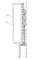
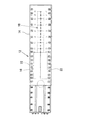
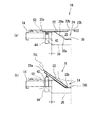
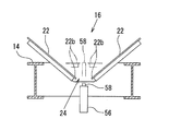
図1および図2には、本発明の実施の形態に係るトレーラ12を示している。このトレーラ12は、いわゆる低床式トレーラであり、床構成部材の姿勢を変更することによって、平床またはV字状床を形成可能な荷台14を備えるものである。図示のトレーラ12は、荷台14の前方寄りの一定範囲には第1の床形状転換構造16を備え、荷台14の後方寄りの一定範囲には第2の床形状転換構造18を備えている。また、荷台14は、図1に示すように、電動開閉式の幌20によって覆われている。
1 and 2 show a
まず、第1の床形状転換構造16について、図2〜図9を参照しながら説明する。
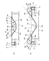
第1の床形状転換構造16は、荷台14の少なくとも一部に、荷台の幅方向中央部で二分割された可動式の床板22を備えている。そして、図4(a)、図5(a)に示すように、床板22に水平姿勢を取らせることで平床が形成される。一方、図4(b)、図5(b)に示すように、床板22の荷台外側端部22aが荷台中央側端部22bに比して高い傾斜姿勢を取らせることで、V字状床が形成されるものである。
First, the first floor
The first floor
また、荷台14には、幅方向中央部を荷台前後方向に延びる凹溝24が設けられている。この凹溝24は、荷台14を構成する複数の横根太26の、荷台幅方向中央部に、荷台幅方向外側から荷台幅方向中央部へ向けて下降する傾斜面28aを有する凹部28(図4(a)、図5(a)参照)を形成し、各横根太26の凹部28を荷台前後方向につなぐようにして板材30で覆うことにより、形成されている。したがって、凹溝24は、各横根太26の凹部28を構成する傾斜面28aに倣った、板材30からなる傾斜面30aをその構成面として有している。そして、床板22は、図4(a)、図5(a)に示すように、その一部が凹溝24に覆い被さるように配置されている。
Further, the
また、第1の床形状転換構造16は、床板22の姿勢変化に係るアクチュエータ32を備えている。アクチュエータ32は、図4に示すように、高圧エアを受けてシリンダロッド34aを伸長させるエアシリンダ34と、内部に封入されたスプリングによってシリンダロッド36aを伸長させ、エアシリンダ34のシリンダロッド34aを押戻すスプリングシリンダ36と、シリンダロッド34a、36aの伸縮動作を、コネクティングロッド38の昇降動作に変換するリンク機構40とを備えている。なお、コネクティングロッド38は、床板22の荷台外側端部22aと、凹溝24の外縁を構成する稜線24aとの間で、床板22の下面に対し軸着されている。図示の例では、このアクチュエータ32は床板22一枚につき一箇所づつ設けられている。
The first floor
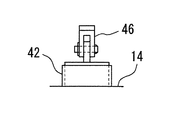
さらに、図5に示すように、床板22の荷台外側端部22aと、凹溝24の外縁を構成する稜線24aとの間の、床板22の下面には、ガイドポスト42が軸着されている。ガイドポスト42は、荷台14に固定されたガイドスリーブ44の内部を上下に摺動自在となっており、ガイドポスト42がガイドスリーブ44内を昇降することにより、床板22に所定の姿勢変化を誘導するガイド手段として機能する。なお、ガイドポスト42は、図3(a)に示すように、床板22一枚につき三箇所づつ設けられている。また、図6には、ガイドポスト42と床板22の下面とをつなぐジョイント46を拡大して示している。
Further, as shown in FIG. 5, a
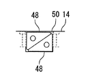
また、第1の床形状転換構造16は、図4(c)に示すように、V字状床の形成時における床板22の姿勢変化を阻止するための、床板22の下面と荷台14との間に挿入されるストッパ48を備えている。ストッパ48は三角形のブロックである。また、未使用時、すなわち、平床の形成時には、ストッパ48は荷台14に形成された収納ポケット50(図3(b)、図7)に、二個一組で収納され、使用時、すなわちV字状溝の形成時には収納ポケット50から取り出され、床板22の荷台外側端部22aと、凹溝24の外縁を構成する稜線24aとの間の、床板22の下面と荷台14との間の複数箇所(図3の例では床板22一枚につき8箇所)に挿入されることで、床板22の全体が安定支持される。なお、図4(c)に示すように、荷台14には、床板22の下面および荷台14に対するストッパ48の密着状態を維持するため、ストッパ48の位置決め用突起52が固定されている。
Moreover, as shown in FIG.4 (c), the 1st floor
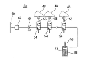
さらに、第1の床形状転換構造16は、図8にその概略的構成を示すように、ストッパ48の未装着状態を表示するための警報手段53を、必要に応じて設けることもできる。警報手段53の警報手段は、床板22の下面と荷台14との間の複数箇所に挿入されたストッパ48の存在を、各挿入箇所毎に検知して、開放状態となるエアバルブ54(本実施の形態では、ストッパ48の全数と同数(8×2=16箇所)だけ設けられている。)と、エアバルブ54を介して供給されるエアにより作動するエアシリンダ56と、エアシリンダ56に駆動される表示部材58を備えている。なお、図示の例では、エアシリンダ56のシリンダロッドを表示部材58として用いている。
Further, as shown in FIG. 8, the first floor
エアバルブ54は、三ポート二位置切換弁でかつ常時閉の弁であるが、ストッパ48が所定の位置に挿入されることで、開放位置へと切り替わるように、ストッパ48の検出杆55を備えている。なお、ストッパ55の検出は、センサ等を用い電気的に行うことも可能であり、その場合には、エアバルブ54にも電磁バルブを採用する。さらに、エアバルブ54に対し、トレーラ12に既存のエア供給ライン60(ブレーキサプライライン等)から、プロテクションバルブ62、手動コック64を介して、高圧エアが供給される回路構成を有している。
The
エアシリンダ56の内部には、表示部材58を常時上方へと付勢するためのコイルスプリング57が設けられており、通常は、表示部材58は図9に仮想線で示すように荷台14上に突出し、その先端部が、平床形成時に水平姿勢をとる床板22の、荷台中央側端部22bの隙間に隠れるような状態となっている。しかしながら、V字状床の形成時には、床板22は荷台中央側端部22bを凹溝24に落ち込むことで、表示部材58は凹溝24の底面から上方へと突出した状態が、明確に視認されることとなる。
Inside the
一方、手動コック64を開放して、エアバルブ54に高圧エアを供給すると、エアバルブ54が全て開状態にあるとき(すなわち、全てのストッパ48の装着完了時。)には、高圧エアはエアシリンダ56へと供給され、コイルスプリング57の付勢力に抗して、表示部材58を下方へと押し下げる。よって、表示部材58は図9に実線で示すように、荷台14の凹24の更に下方(荷台下)に格納される。他方、複数のエアバルブの54の一つでも閉状態にあるとき(すなわち、ストッパ48の装着未完了時。)には、高圧エアはエアシリンダ56へは供給されず、表示部材58は、凹溝24の底面から上方へと突出した状態が維持される。
On the other hand, when the
続いて、トレーラ12の、第2の床形状転換構造18について、図2、図10、図11を参照しながら説明する。
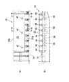
第2の床形状転換構造18は、荷台14の少なくとも一部に設けられた、荷台14の幅方向中央部を荷台前後方向に延びる断面V字状の凹溝24を備えている。凹溝24については、第1の床形状転換構造16と同様であることから、詳しい説明を省略する。そして、第2の床形状転換構造18は、荷台14の幅方向で対称形をなし、凹溝24を構成する傾斜面30aに自らの傾斜面66a、66aを密着させた状態で、凹溝24内に格納可能なブロック対66を備えている。また、ブロック対66、66は、図10(b)に符号A〜Kを付して示すように、荷台14の前後方向に等間隔となるように、複数対(図示の例では11対)設けられている。
Next, the second floor
The second floor
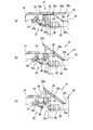
そして、図11(a)に示すように、ブロック対66、66が凹溝24内に格納された状態で平床が形成され、図11(b)に示すように、ブロック対66、66が凹溝24の外縁(稜線24a)に沿って平床上に載置された状態で、ブロック対66、66の傾斜面66a、66aと凹溝24の傾斜面30aとによりV字状床が構成される。
Then, as shown in FIG. 11A, a flat floor is formed in a state where the block pairs 66 and 66 are stored in the recessed
なお、図10(b)に示すように、V字状床の形成時には、ブロック対66、66の傾斜面66a、66aは、一定間隔で帯状に立ちあがり、一定幅の帯状のコイル支持体を構成するものであるが、図10(a)に示すように平床の形成時には、凹溝24の全体を覆い隠すことが可能となるように、ブロック対66、66の水平面66b、66bには、カバープレート68、68が固定されている。なおカバープレート68は、各ブロック66、66毎に独立して設ける必要はなく、図10(a)に示す例では、カバープレート68Bにはブロック対66B、66Cが固定され、カバープレート68Dにはブロック対66E、66Fが固定され、カバープレート68Fにはブロック対66H、66Iが固定されており、カバープレートの数は全部で十六枚(8×2=16)となっている。
As shown in FIG. 10 (b), when the V-shaped floor is formed, the
さらに、第2の床形状転換構造18は、図10(b)、図11(b)に示すV字状床の構成時に、カバープレート68、68の位置決めを行うことによってブロック対66、66の位置を固定するための、複数のステーキ70を、着脱自在に備えている。なお、ステーキ70は、荷台14に設けられたステーキポケット72に対し、向きを変えて指し込むことで、図11(a)に示すように荷台14の下方に隠れる格納状態と、図11(b)に示す突出状態とを変更することができる。そして、図11(b)に示す突出状態では、ステーキ70の位置決め突起70aが、カバープレート68、68、またはブロック対66、66の鉛直面66c、66cと当接し、ブロック対66、66の位置を固定することができる。
Further, the second floor
なお、図示の例では、ブロック対66、66の姿勢を、図11(a)に示す格納状態と、図11(b)に示す突出状態との間で変更する際には、作業者が、カバープレート68、68と一体になったブロック対66、66を各々持上げて、向きおよび載置場所を変更する作業手順をとるものである。しかしながら、例えば、ブロック対66、66を凹溝24の稜線24aにおいて荷台14に軸着することとすれば、カバープレート68、68と共にブロック対66、66を回転させることによって、格納状態と突出状態との変更が可能となる。なお、この場合には、ブロック対66、66の回転作業時にブロック対66、66同士が干渉しないように、ブロック対66、66の鉛直面66c、66cの形状を若干切り欠く必要がある。
In the illustrated example, when the posture of the
上記構成をなす本発明の実施の形態により得られる作用効果は、以下の通りである。まず、本発明の実施の形態に係る第1、第2の床形状転換構造16、18よれば、貨物の荷役作業時に、床構成部材(床板22若しくはブロック対66,66)の姿勢を変更することのみによって、汎用性の高い平床と、V字状床、すなわち、図5(b)、図11(b)に二点鎖線で示すコイル状重量物74L、74Sの外周面を、下方から挟み込むようにして支持することで搭載時の安定性を高めることが可能な床とを、1台のトレーラ12でありながら、必要に応じて使い分けることが可能となる。
The effects obtained by the embodiment of the present invention having the above-described configuration are as follows. First, according to the first and second floor
そして、第1の床形状転換構造16の場合には、可動式の床板22の姿勢を変化させることで、荷台の形状を平床とV字状床との間で転換することが可能となる。
しかも、床板22の、荷台の幅方向中央部に設けた凹溝24に覆い被さる部分を、図4(b)、図5(b)に示すように、凹溝24に落し込むことによってV字状床を構成することが可能となるので、V字状床の形成時におけるコイル状重量物74L、74Sの搭載高さを低く抑えることが可能となる。よって、コイル状重量物の荷役作業をより円滑に行うことが可能となる。しかも、コイル状重量物の積載時における、トレーラ12の重心を低く抑え、より安定した走行が可能となる。
And in the case of the 1st floor
Moreover, as shown in FIGS. 4 (b) and 5 (b), the portion of the
また、床板22の凹溝24に覆い被さる部分以外の部分は、図4(b)、図5(b)に示すように、凹溝から斜め上方へと突出し、広い面積の傾斜面を形成することとなるので、コイル状重量物の直径が比較的小径の物74Sから比較的大径の物74Lまで、床板22を適切な部位に当接させ、これらの貨物を安定支持することが可能となる。
なお、凹溝24の断面形状は図示の例に限定されるものではないが、凹溝24を構成する面には、V字状床の形成時に床板22の下面の一部が密着するための、荷台幅方向外側から荷台幅方向中央部へ向けて下降する傾斜面30aが含まれることで、床板22の下面の一部が凹溝24の傾斜面30aに当接し、V字状床の形成時における、床板22の姿勢の安定性をより高めることができる。
Further, as shown in FIGS. 4B and 5B, the portion other than the portion covering the
In addition, although the cross-sectional shape of the ditch | groove 24 is not limited to the example of illustration, a part of lower surface of the
さらに、第1の床形状転換構造16では、凹溝24の外縁を構成する稜線24aが、床板の姿勢変化時の回転中心として機能するものである。この構成によれば、荷台14の構造物に床板22をヒンジ結合することなく、床板22の姿勢変化を可能とし、ヒンジを用いた場合に憂慮される当該ヒンジへの荷重の集中が生じ得ず、可動式の床板22の、可動機構の信頼性をより高めることに貢献している。
なお、床板22には、ガイドスリーブ44内を昇降するガイドポスト42が軸着されていることにより、床板22を荷台14にヒンジ結合することなく、床板22に所定の姿勢変化を誘導することが可能となっている。
Furthermore, in the 1st floor
The
また、床板22の姿勢変化に係るアクチュエータ32を備えることで、荷台の形状を平床とV字状床との間で転換させる作業の容易化を図ることができる。なお、当該転換作業にアクチュエータを用いることなく、人力によって行うこととすれば、第1の床形状転換構造16はより簡素なものとなる。
また、第1の床形状転換構造16では、ストッパ48によって、V字状床の形成時における床板22の姿勢変化を阻止し、V字状床の形成時における、前記床板の姿勢の安定性をより一層高めている。
In addition, by providing the
Further, in the first floor
さらに、第1の床形状転換構造16に、ストッパ48の未装着状態を表示する警報手段53を設けることとすれば、V字状床の形成時における作業者の点検作業の簡便化を図ることができる。警報手段53は、ストッパ48の存在を検知して開放するエアバルブ54と、エアバルブ54を介して供給されるエアにより作動するエアシリンダ56と、エアシリンダ56に駆動され、ストッパ48の装着未完了時に荷台14上に突出し、装着完了時に荷台下に格納される表示部材58とを備えるものであり、エア駆動によって荷台下に格納される表示部材58により、ストッパの装着完了を作業者に明確に認知させることができる。
Furthermore, if the alarm means 53 for displaying the non-attached state of the
一方、第2の床形状転換構造18によっても、ブロック対66、66の姿勢を変化させることのみによって、汎用性の高い平床(図10(a)、図11(a))と、V字状床(図11(a)、図11(b))とを、1台のトレーラ12でありながら、必要に応じて使い分けることが可能となる。
しかも、V字状床を構成する傾斜面が凹溝24の傾斜面24aとブロック対66、66の傾斜面66a、66aとの連続面として形成されることから、広い面積の傾斜面を形成することとなり、コイル状重量物の直径が比較的小径の物74Sから比較的大径の物74Lまで、傾斜面24aまたは傾斜面66aを適切な部位に当接させ、これらの貨物を安定支持することが可能となる。また、V字状床の底部は凹溝24の底部でもあることから、V字状床の底部は荷台14に落し込まれるように構成されることとなり、V字状床の形成時における貨物の搭載高さを低く抑えることが可能となる。よって、コイル状重量物の荷役作業をより円滑に行うことが可能となる。また、コイル状重量物の積載時における、トレーラ12の重心を低く抑え、より安定した走行が可能となる。
さらに、V字状床の構成時には、ステーキ70によってブロック対66、66の位置を固定することで、V字状床の形成時における、ブロック対の安定性をより一層高めることが可能となる。
On the other hand, the second floor
Moreover, since the inclined surface constituting the V-shaped floor is formed as a continuous surface of the
Furthermore, when the V-shaped floor is configured, the position of the block pairs 66 and 66 is fixed by the
なお、本発明の実施の形態では、第1の床形状転換構造16、第2の床形状転換構造18を、1台の低床式トレーラ12に組み込んだ例を示しているが、いずれか一方の構造に統一してトレーラに組み込むこととしても良い。特に、第1の床形状転換構造16に統一した場合には、床形状の転換作業が容易となる。一方、第2の床形状転換構造18に統一した場合には、低床式トレーラ12への適用が容易となる。
いずれにしても、コイル状重量物の搬送時における荷役作業をより円滑に行うことを可能としつつ、必要に応じて荷台14の形状を平床に転換することで、様々な積荷の搬送が可能となり、1台のトレーラ12を、様々な用途に使用することが可能となる。
In the embodiment of the present invention, an example in which the first floor
In any case, various loads can be transported by changing the shape of the
12:トレーラ、14:荷台、16:第1の床形状転換構造、18:第2の床形状転換構造、22:床板、22a:荷台外側端部、22b:荷台中央側端部、24:凹溝、24a:稜線、30a:傾斜面、32:アクチュエータ、34:エアシリンダ、34a:シリンダロッド、36:スプリングシリンダ、36a:シリンダロッド、38:コネクティングロッド、40:リンク機構、42:ガイドポスト、44:ガイドスリーブ、48:ストッパ、53:警報手段、54:エアバルブ、56:エアシリンダ、57:コイルスプリング、58:表示部材、66:ブロック対、66a:傾斜面、68:カバープレート、70:ステーキ
12: trailer, 14: cargo bed, 16: first floor shape change structure, 18: second floor shape change structure, 22: floor plate, 22a: load bed outer side edge, 22b: load bed center side edge, 24: concave Groove, 24a: Ridge line, 30a: Inclined surface, 32: Actuator, 34: Air cylinder, 34a: Cylinder rod, 36: Spring cylinder, 36a: Cylinder rod, 38: Connecting rod, 40: Link mechanism, 42: Guide post, 44: guide sleeve, 48: stopper, 53: alarm means, 54: air valve, 56: air cylinder, 57: coil spring, 58: display member, 66: block pair, 66a: inclined surface, 68: cover plate, 70: steak
Claims (12)
当該床板に水平姿勢を取らせることで前記平床が形成され、
当該床板の荷台外側端部が荷台中央側端部に比して高い傾斜姿勢を取らせることで前記V字状床が形成されることを特徴とする請求項1記載のトレーラ。 At least a part of the loading platform is provided with a movable floor plate that is divided into two at the center in the width direction of the loading platform
The flat floor is formed by letting the floor plate take a horizontal posture,
2. The trailer according to claim 1, wherein the V-shaped floor is formed by causing the loading platform outer side end portion of the floor board to take a higher inclined posture than the loading platform center side end portion.
当該ブロック対が前記凹溝内に格納された状態で前記平床が形成され、
前記ブロック対が前記凹溝の外縁に沿って荷台上に載置された状態で、前記ブロック対の傾斜面と前記凹溝の傾斜面とにより前記V字状床が構成されることを特徴とする請求項1記載のトレーラ。 A concave groove having a V-shaped cross section extending in the longitudinal direction of the loading platform and a symmetric shape in the width direction of the loading platform, provided in at least a part of the loading platform in the width direction center of the loading platform, and an inclined surface constituting the concave groove With a block pair that can be stored in the concave groove in a state where its inclined surface is closely attached,
The flat floor is formed in a state where the block pair is stored in the concave groove,
The V-shaped floor is constituted by the inclined surface of the block pair and the inclined surface of the concave groove in a state in which the block pair is placed on a cargo bed along the outer edge of the concave groove. The trailer according to claim 1.
The low-floor type trailer according to any one of claims 1 to 11.
Priority Applications (1)
| Application Number | Priority Date | Filing Date | Title |
|---|---|---|---|
| JP2004119219A JP2005297853A (en) | 2004-04-14 | 2004-04-14 | Trailer |
Applications Claiming Priority (1)
| Application Number | Priority Date | Filing Date | Title |
|---|---|---|---|
| JP2004119219A JP2005297853A (en) | 2004-04-14 | 2004-04-14 | Trailer |
Publications (1)
| Publication Number | Publication Date |
|---|---|
| JP2005297853A true JP2005297853A (en) | 2005-10-27 |
Family
ID=35329912
Family Applications (1)
| Application Number | Title | Priority Date | Filing Date |
|---|---|---|---|
| JP2004119219A Pending JP2005297853A (en) | 2004-04-14 | 2004-04-14 | Trailer |
Country Status (1)
| Country | Link |
|---|---|
| JP (1) | JP2005297853A (en) |
Citations (4)
| Publication number | Priority date | Publication date | Assignee | Title |
|---|---|---|---|---|
| JPS49112314A (en) * | 1973-02-14 | 1974-10-25 | ||
| JPS60176838A (en) * | 1984-02-22 | 1985-09-10 | Shin Meiwa Ind Co Ltd | Transport vehicle |
| JPS6234830A (en) * | 1985-08-08 | 1987-02-14 | ベルテイル・イサクソン | Rolling preventive device for circular body |
| JPS63115841U (en) * | 1987-01-22 | 1988-07-26 |
-
2004
- 2004-04-14 JP JP2004119219A patent/JP2005297853A/en active Pending
Patent Citations (4)
| Publication number | Priority date | Publication date | Assignee | Title |
|---|---|---|---|---|
| JPS49112314A (en) * | 1973-02-14 | 1974-10-25 | ||
| JPS60176838A (en) * | 1984-02-22 | 1985-09-10 | Shin Meiwa Ind Co Ltd | Transport vehicle |
| JPS6234830A (en) * | 1985-08-08 | 1987-02-14 | ベルテイル・イサクソン | Rolling preventive device for circular body |
| JPS63115841U (en) * | 1987-01-22 | 1988-07-26 |
Similar Documents
| Publication | Publication Date | Title |
|---|---|---|
| US4754709A (en) | Railroad car for containers having guides for the containers | |
| KR101933858B1 (en) | Container | |
| ES2433366T3 (en) | Transport container with cargo and method of loading stowage in a transport container | |
| WO2007018672A3 (en) | Cargo container handling system and associated method | |
| JP2011148358A (en) | Ship | |
| CN102652100A (en) | Pallet rack, pallet rack unit, and container provided with pallet racks | |
| JP2005297853A (en) | Trailer | |
| FR2894215A1 (en) | METHOD, SYSTEM AND DEVICES FOR TRANSPORTING CONTAINERS | |
| WO2002049875A8 (en) | Pickup truck with cab-over-engine and goods or passenger transport platform | |
| CN101107160A (en) | Cargo handling arrangement and system on a cargo ship | |
| JP3280632B2 (en) | Storage structure for coiled heavy goods pallet and coiled heavy goods loading pallet in transport container | |
| JP2006044730A (en) | Method and apparatus for loading vehicle | |
| NO20052243L (en) | Container for bulk cargo and transport system including such. | |
| JP5010147B2 (en) | Ship | |
| US20170217696A1 (en) | Lift beam system | |
| JP5570624B2 (en) | The structure of a car carrier | |
| JP4866105B2 (en) | Rack freight container | |
| JP3414781B2 (en) | Horizontal mobile cargo handling equipment | |
| JPH0733192A (en) | Container | |
| JP4221325B2 (en) | Vehicle loading method and apparatus | |
| JP3121486U (en) | Open container | |
| JP3223478U (en) | Transition board | |
| ITTO20030143U1 (en) | MODIFIED CONTAINER FOR MARITIME SHIPMENT | |
| JP2009196771A (en) | Bulk cargo unloading device for self-unloading ship | |
| JP2008126723A (en) | Loading truck |
Legal Events
| Date | Code | Title | Description |
|---|---|---|---|
| A621 | Written request for application examination |
Free format text: JAPANESE INTERMEDIATE CODE: A621 Effective date: 20070410 |
|
| A977 | Report on retrieval |
Free format text: JAPANESE INTERMEDIATE CODE: A971007 Effective date: 20091125 |
|
| A131 | Notification of reasons for refusal |
Effective date: 20091216 Free format text: JAPANESE INTERMEDIATE CODE: A131 |
|
| A521 | Written amendment |
Effective date: 20100215 Free format text: JAPANESE INTERMEDIATE CODE: A523 |
|
| A131 | Notification of reasons for refusal |
Effective date: 20100421 Free format text: JAPANESE INTERMEDIATE CODE: A131 |
|
| A02 | Decision of refusal |
Free format text: JAPANESE INTERMEDIATE CODE: A02 Effective date: 20100901 |