JP2005297848A - Refueling port structure of vehicle - Google Patents
Refueling port structure of vehicle Download PDFInfo
- Publication number
- JP2005297848A JP2005297848A JP2004119119A JP2004119119A JP2005297848A JP 2005297848 A JP2005297848 A JP 2005297848A JP 2004119119 A JP2004119119 A JP 2004119119A JP 2004119119 A JP2004119119 A JP 2004119119A JP 2005297848 A JP2005297848 A JP 2005297848A
- Authority
- JP
- Japan
- Prior art keywords
- fuel filler
- vehicle
- fuel
- base
- opening
- Prior art date
- Legal status (The legal status is an assumption and is not a legal conclusion. Google has not performed a legal analysis and makes no representation as to the accuracy of the status listed.)
- Pending
Links
Images
Landscapes
- Cooling, Air Intake And Gas Exhaust, And Fuel Tank Arrangements In Propulsion Units (AREA)
Abstract
【課題】 外観的に見栄えが良好で、コストが安価で、製造工程が簡略化された車両の給油口部構造を提供する。
【解決手段】 ボディサイドアウタパネル3の側方に給油口用の開口部5を設け、該開口部5にフューエルフィラーリッドアセンブリ13を設けた車両の給油口部構造であって、前記フューエルフィラーリッドアセンブリ13は、前記開口部5の周縁のフランジ7に取り付けられるフューエルフィラーベース9と、該フューエルフィラーベース9に開閉自在に支持されたフューエルフィラーリッド15と備え、これらのフューエルフィラーベース9及びフューエルフィラーリッド15を一体に組み付けたのちにボディサイドアウタパネル3に取り付けられることを特徴としている。
【選択図】 図2PROBLEM TO BE SOLVED: To provide a fuel filler opening structure for a vehicle that has a good appearance, is inexpensive, and has a simplified manufacturing process.
A fuel filler opening structure for a vehicle in which an opening portion for a fuel filler opening is provided on a side of a body side outer panel, and a fuel filler lid assembly is provided in the opening portion, the fuel filler lid assembly. 13 includes a fuel filler base 9 attached to the flange 7 on the periphery of the opening 5 and a fuel filler lid 15 supported by the fuel filler base 9 so as to be openable and closable. The fuel filler base 9 and the fuel filler lid 13 15 is attached to the body side outer panel 3 after being assembled integrally.
[Selection] Figure 2
Description
本発明は、車両の給油口部構造に関し、更に詳しくは、モジュールによって一体化を図った給油口部の構造に関する。 The present invention relates to a fuel filler port structure of a vehicle, and more particularly to a structure of a fuel filler port unit integrated by a module.
従来の給油口は、例えば、車両後部に設けられている。具体的には、ボディサイドアウタのリヤフェンダ部及びホイールハウスアウタに開口部を形成し、このホイールハウスアウタの開口部にフューエルチューブを設けると共に、ボディサイドアウタの開口部の周縁には、フューエルフィラーベースを接合しており、このボディサイドアウタとフューエルフィラーベースとの合せ部には、水密用塗装シールが塗布されている。また、ホイールハウスアウタの開口部には、フューエルフィラーリッドが開閉自在に取り付けられている。 The conventional fuel filler port is provided in the rear part of the vehicle, for example. Specifically, an opening is formed in the rear fender portion of the body side outer and the wheel house outer, a fuel tube is provided in the opening portion of the wheel house outer, and a fuel filler base is provided on the periphery of the opening portion of the body side outer. A watertight paint seal is applied to the joint between the body side outer and the fuel filler base. A fuel filler lid is attached to the opening of the wheel house outer so as to be freely opened and closed.
さらに、フューエルフィラーベースの側部には、水密性を確保するために、パッキンを介してフューエルフィラーロックが取り付けられている。 Further, a fuel filler lock is attached to the side portion of the fuel filler base via a packing in order to ensure water tightness.
そして、給油口部の製造手順は、まず、車体工程にてフューエルフィラーベースをボディサイドアウタのリヤフェンダ部に接合したのち、組立工程にて、グロメット、フューエルフィラーロック及びフューエルフィラーリッド等を組み付けている(例えば、特許文献1,2参照)。
しかしながら、前記従来例では、ボディサイドアウタとフューエルフィラーベースとの合せ部に、水密用塗装シールが塗布されているため、外観的に見栄えが良好でないという問題がある。 However, the conventional example has a problem that the appearance is not good because the watertight paint seal is applied to the joint portion of the body side outer and the fuel filler base.
また、パッキンを介してフューエルフィラーロックが取り付けられているため、パッキンの部品コストが嵩み、シール性を充分に確保することが困難であるという問題がある。 Further, since the fuel filler lock is attached via the packing, there is a problem that the cost of the packing parts increases and it is difficult to sufficiently secure the sealing performance.
さらに、給油口部の組付工程が、車体工程と組立工程とに分かれているため、作業が複雑になり、寸法精度の確保が困難になるという問題がある。 Furthermore, since the assembly process of the fuel filler port is divided into a vehicle body process and an assembly process, there is a problem that the operation becomes complicated and it is difficult to ensure dimensional accuracy.
そこで、本発明は、外観的に見栄えが良好で、コストが安価で、製造工程が簡略化された車両の給油口部構造を提供することを目的としている。 SUMMARY OF THE INVENTION Accordingly, an object of the present invention is to provide a vehicle fuel filler port structure that has a good appearance, is inexpensive, and has a simplified manufacturing process.
前記目的を達成するために、本発明に係る車両の給油口部構造は、車体に開口部を設け、該開口部にフューエルフィラーリッドアセンブリを設けた車両の給油口部構造であって、前記フューエルフィラーリッドアセンブリは、前記開口部の周縁に取り付けられるフューエルフィラーベースと、該フューエルフィラーベースに開閉自在に支持されたフューエルフィラーリッドと備え、これらのフューエルフィラーベース及びフューエルフィラーリッドを一体に組み付けたのちに車体に取り付けることを特徴としている。 In order to achieve the above object, a vehicle fuel supply port structure according to the present invention is a vehicle fuel supply port structure in which an opening is provided in a vehicle body, and a fuel filler lid assembly is provided in the opening. The filler lid assembly includes a fuel filler base that is attached to the periphery of the opening, and a fuel filler lid that is supported by the fuel filler base so that it can be opened and closed. After the fuel filler base and the fuel filler lid are assembled together, It is characterized by being attached to the car body.
本発明に係る車両の給油口部構造によれば、フューエルフィラーベース及びフューエルフィラーリッドを一体に組み付けたのちに車体に取り付けるため、作業工数及び作業工程を削減することができる。即ち、従来は、車体工程においてフューエルフィラーベースを車体に取り付けたのち、組立工程においてフューエルフィラーリッドを組み付けるという別々の工程で取付作業を行っていたが、本発明によれば、例えば、組立工程において一時に組み付けることができる。 According to the fuel filler port structure of a vehicle according to the present invention, the fuel filler base and the fuel filler lid are assembled together and then attached to the vehicle body, so that the number of work steps and work steps can be reduced. That is, conventionally, the mounting operation was performed in a separate process of assembling the fuel filler lid in the assembly process after the fuel filler base was mounted on the vehicle body in the vehicle body process, but according to the present invention, for example, in the assembly process Can be assembled at a time.
以下、本発明の実施形態を図面と共に詳述する。 Hereinafter, embodiments of the present invention will be described in detail with reference to the drawings.
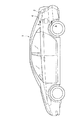
図1は本発明に係る給油口部構造を採用した車両の側面図である。 FIG. 1 is a side view of a vehicle that employs a fuel filler opening structure according to the present invention.
車両1の側部にはボディサイドアウタパネル(車体)3が設けられ、該ボディサイドアウタパネル3の後部のリヤフェンダ部分には、給油口部4が設けられている。
A body side outer panel (vehicle body) 3 is provided at a side portion of the vehicle 1, and a fuel filler opening 4 is provided at a rear fender portion of the rear portion of the body side
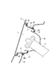
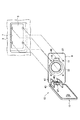
図2は図1のA−A線による拡大断面図、図3は本発明に係る給油口部の分解斜視図である。 2 is an enlarged cross-sectional view taken along line AA in FIG. 1, and FIG. 3 is an exploded perspective view of a fuel filler port according to the present invention.
図2,3に示すように、ボディサイドアウタパネル3には、側面視略矩形状に形成された給油口用の開口部5が設けられ、該開口部5の周縁は、車両内側方向に向けて段差状に落ち込んだフランジ7に形成されている。このフランジ7には、上下にそれぞれ2つずつの取付孔11が穿設されており、後述するように、該取付孔11にリベットを介してフューエルフィラーリッドアセンブリ13が取り付けられる。
As shown in FIGS. 2 and 3, the body side
また、フューエルフィラーリッドアセンブリ13は、ボディサイドアウタパネル3の開口部周縁のフランジ7にリベット(図示せず)を介して取り付けられるフューエルフィラーベース9と、該フューエルフィラーベース9に回動自在に支持されたフューエルフィラーリッド15とが一体に組み付けられてモジュール化されている。これらのフューエルフィラーベース9及びフューエルフィラーリッド15は、共に、合成樹脂によって成形されている。
The fuel
フューエルフィラーベース9の外形は、ボディサイドアウタパネル3の開口部周縁の形状に対応した矩形状に形成されており、上下に2つずつの取付孔11,11が穿設されている。また、フューエルフィラーベース9の中央部には、フューエルチューブ17が挿通するフューエルチューブ用フランジ19が略円錐台状に形成されている。このフューエルチューブ用フランジ19は、平面状のベース本体21から、径が徐々に狭まるように車両内側方向に延びる傾斜部23と、該傾斜部23の車両内側の端部から屈曲してベース本体21とほぼ平行に延びる屈曲部25とから構成されている。図2に示すように、フューエルフィラーベース9の外周縁の裏面側には、水密性を有するシール材であるスポンジ27が設けられ、フューエルフィラーベース9の外周縁は、ボディサイドアウタパネル3のフランジ7にスポンジ27を介して密着して取り付けられている。
The outer shape of the
この傾斜部23の外周には、リング状のグロメット29が固着されている。該グロメット29は、内周側が平坦で、外周側に溝29aが形成されており、この溝29aに、ホイールハウスアウタ31の開口周縁が嵌合されている。
A ring-
また、フューエルフィラーベース9の屈曲部25に形成したフューエルチューブ用孔33の内周縁には、別のグロメット37が嵌合されている。フューエルチューブ17の先端の外周には、筒状のチューブ用パネル39が取り付けられおり、該チューブ用パネル39の車両外側の端部にグロメット37が当接している。
Further, another
そして、フューエルフィラーベース9の前端部には、車両外側に向けて上下一対の舌片41,41が突設されており、これらの舌片41,41に対応して、フューエルフィラーリッド15の前端部にも一対の舌片43,43が設けられている。これらの舌片同士41,43は、ピン45を介して回動自在に結合され、また、このピン45には、フューエルフィラーリッド15が車両外側に開くようにスプリング47が付勢された状態で設けられている。
A pair of upper and
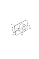
さらに、図3,4に示すように、フューエルチューブ用フランジ19の後部には、フューエルフィラーロック49が配置されている。このフューエルフィラーロック49は、例えば、射出成形などの工法によってフューエルフィラーベース9に一体成形されている。なお、フューエルフィラーロック49の後面には、フューエルフィラーロック用ケーブル51が接続されている。
Further, as shown in FIGS. 3 and 4, a
前記構成を有するフューエルフィラーリッドアセンブリ13を車体に組み付ける手順を簡単に説明する。
A procedure for assembling the fuel
まず、図3に示すように、予め、フューエルフィラーリッドアセンブリ13自体を組み付けておく。例えば、フューエルフィラーベース9の舌片41,41にフューエルフィラーリッド15の舌片43,43を嵌め込み、スプリング47を取り付けたピン45によって、前記舌片同士41,43を結合する。
First, as shown in FIG. 3, the fuel
そして、車両1の組立工程(トリムライン)において、フューエルフィラーリッドアセンブリ13を車両1の外側方向から、ボディサイドアウタパネル3のフランジ7にリベット等によって取り付ける。
Then, in the assembly process (trim line) of the vehicle 1, the fuel
以下に、本発明の実施形態による作用効果を説明する。 Below, the effect by embodiment of this invention is demonstrated.
前記フューエルフィラーリッドアセンブリ13は、フューエルフィラーベース9に一体成形されたフューエルフィラーロック49を更に備えているため、従来からフューエルフィラーロック49に取り付けていた水密性のパッキンが不要になり、部品点数の削減と共に、コスト低減を図ることができる。
Since the fuel
前記フューエルフィラーリッドアセンブリ13を車両1の外側方向からボディサイドアウタパネル3に取り付けるように構成すると共に、このフューエルフィラーリッドアセンブリ13の取付けを車両1の組立工程においてのみ行うようにしたため、従来のように、給油口部の組付工程が複数に分かれることがなくなり、作業工程の簡素化を図ることができ、生産性が向上する。
Since the fuel
そして、ボディサイドアウタパネル3の開口部周縁のフランジ7にスポンジ27を設け、このスポンジ27を介して、フューエルフィラーリッドアセンブリ13のフューエルフィラーベース9を取り付けたため、従来のように、ボディサイドアウタとフューエルフィラーベース9との合せ部に塗布されていた水密用塗装シールが不要になるため、外観的に見栄えが良好となる。
And since the sponge 27 was provided in the flange 7 of the opening part periphery of the body side
前記フューエルフィラーベース9にフューエルチューブ用孔33を設け、該フューエルチューブ用孔33から車両外側に向けてフューエルチューブ17の先端を臨ませると共に、前記フューエルフィラーリッド15とフューエルフィラーベース9を合成樹脂によって成形しているため、車両1が衝突を起こしたときに、フューエルフィラーリッド15とフューエルフィラーベース9を変形させて衝撃エネルギーを効率的に吸収させ、フューエルチューブ17への入力荷重を極力抑制することができる。
The
3…ボディサイドアウタパネル(車体)
4…給油口部
5…開口部
9…フューエルフィラーベース
13…フューエルフィラーリッドアセンブリ
15…フューエルフィラーリッド
17…フューエルチューブ
27…スポンジ(シール材)
33…フューエルチューブ用孔
49…フューエルフィラーロック
3. Body side outer panel (vehicle body)
DESCRIPTION OF SYMBOLS 4 ... Refueling
33 ... Hole for
Claims (5)
前記フューエルフィラーリッドアセンブリは、前記開口部の周縁に取り付けられるフューエルフィラーベースと、該フューエルフィラーベースに開閉自在に支持されたフューエルフィラーリッドと備え、これらのフューエルフィラーベース及びフューエルフィラーリッドを一体に組み付けたのちに車体に取り付けることを特徴とする車両の給油口部構造。 A vehicle fuel filler port structure in which an opening is provided in a vehicle body and a fuel filler lid assembly is provided in the opening,
The fuel filler lid assembly includes a fuel filler base that is attached to the periphery of the opening, and a fuel filler lid that is supported by the fuel filler base so as to be openable and closable. The fuel filler base and the fuel filler lid are assembled together. A vehicle fuel filler opening structure that is attached to a vehicle body afterwards.
Priority Applications (1)
| Application Number | Priority Date | Filing Date | Title |
|---|---|---|---|
| JP2004119119A JP2005297848A (en) | 2004-04-14 | 2004-04-14 | Refueling port structure of vehicle |
Applications Claiming Priority (1)
| Application Number | Priority Date | Filing Date | Title |
|---|---|---|---|
| JP2004119119A JP2005297848A (en) | 2004-04-14 | 2004-04-14 | Refueling port structure of vehicle |
Publications (1)
| Publication Number | Publication Date |
|---|---|
| JP2005297848A true JP2005297848A (en) | 2005-10-27 |
Family
ID=35329908
Family Applications (1)
| Application Number | Title | Priority Date | Filing Date |
|---|---|---|---|
| JP2004119119A Pending JP2005297848A (en) | 2004-04-14 | 2004-04-14 | Refueling port structure of vehicle |
Country Status (1)
| Country | Link |
|---|---|
| JP (1) | JP2005297848A (en) |
Cited By (7)
| Publication number | Priority date | Publication date | Assignee | Title |
|---|---|---|---|---|
| JP2008132953A (en) * | 2006-11-28 | 2008-06-12 | Kia Motors Corp | Fuel door housing equipment |
| US7390048B2 (en) * | 2005-08-26 | 2008-06-24 | Toyoda Gosei Co., Ltd. | Shield member |
| FR2930914A1 (en) * | 2008-05-06 | 2009-11-13 | Renault Sas | DEVICE FOR FASTENING A FUEL TRAP ASSEMBLY |
| EP2168804A1 (en) * | 2008-09-29 | 2010-03-31 | Peugeot Citroën Automobiles S.A. | System for precisely mounting a fuel door in an opening made in the metal sheet of an automobile body |
| JP2013116653A (en) * | 2011-12-02 | 2013-06-13 | Honda Motor Co Ltd | Fuel lid part structure |
| RU2527876C2 (en) * | 2008-06-11 | 2014-09-10 | Рено С.А.С. | Attachment of filling neck hatch assembly at carrier body |
| JP2015044438A (en) * | 2013-08-27 | 2015-03-12 | トヨタ自動車株式会社 | Inlet pipe peripheral structure |
-
2004
- 2004-04-14 JP JP2004119119A patent/JP2005297848A/en active Pending
Cited By (10)
| Publication number | Priority date | Publication date | Assignee | Title |
|---|---|---|---|---|
| US7390048B2 (en) * | 2005-08-26 | 2008-06-24 | Toyoda Gosei Co., Ltd. | Shield member |
| JP2008132953A (en) * | 2006-11-28 | 2008-06-12 | Kia Motors Corp | Fuel door housing equipment |
| FR2930914A1 (en) * | 2008-05-06 | 2009-11-13 | Renault Sas | DEVICE FOR FASTENING A FUEL TRAP ASSEMBLY |
| WO2009138703A1 (en) * | 2008-05-06 | 2009-11-19 | Renault S.A.S. | Device for securing a fuel filler flap assembly |
| CN102015351A (en) * | 2008-05-06 | 2011-04-13 | 雷诺股份公司 | Device for securing a fuel filler flap assembly |
| RU2527876C2 (en) * | 2008-06-11 | 2014-09-10 | Рено С.А.С. | Attachment of filling neck hatch assembly at carrier body |
| EP2168804A1 (en) * | 2008-09-29 | 2010-03-31 | Peugeot Citroën Automobiles S.A. | System for precisely mounting a fuel door in an opening made in the metal sheet of an automobile body |
| FR2936448A1 (en) * | 2008-09-29 | 2010-04-02 | Peugeot Citroen Automobiles Sa | DEVICE FOR PRECISIONALLY FITTING A FUEL HATCH IN AN OPENING MADE IN THE SHEET OF THE BOX OF A MOTOR VEHICLE |
| JP2013116653A (en) * | 2011-12-02 | 2013-06-13 | Honda Motor Co Ltd | Fuel lid part structure |
| JP2015044438A (en) * | 2013-08-27 | 2015-03-12 | トヨタ自動車株式会社 | Inlet pipe peripheral structure |
Similar Documents
| Publication | Publication Date | Title |
|---|---|---|
| JP3920257B2 (en) | Side sill garnish mounting structure | |
| JP6242107B2 (en) | Vehicle back door assembly structure | |
| JP2006015834A (en) | Front fender structure | |
| JP3715172B2 (en) | mirror | |
| JP4738445B2 (en) | Vehicle fuel supply structure | |
| JP5125300B2 (en) | Fixed window structure of automobile | |
| CN111422262A (en) | Hydrogen filling structure | |
| JP2011168213A (en) | Door structure for vehicle | |
| JP2006282119A (en) | Vehicle roof side mounting structure | |
| JP3671912B2 (en) | Rear window structure of automobile | |
| JP5708337B2 (en) | Vehicle door trim | |
| JP5590311B2 (en) | Door trim | |
| JP2008068765A (en) | Resin roof structure for vehicles | |
| JP2012131274A (en) | Tongue storage structure of seat belt | |
| JP4264331B2 (en) | Rear body structure of automobile | |
| JP5521767B2 (en) | Door trim | |
| JP6477353B2 (en) | Door trim | |
| JP5655740B2 (en) | Vehicle fuel adapter mounting structure | |
| JP6052602B2 (en) | Front pillar trim and instrument panel alignment structure | |
| JP2007076617A (en) | Body side structure | |
| JP5343717B2 (en) | Mounting structure for vehicle interior parts | |
| JP2007131281A (en) | Bumper mounting structure | |
| JP2012127394A (en) | Bracket | |
| JP4412668B2 (en) | Interior lining | |
| JP2009248736A (en) | Vehicular door trim |