JP2005297814A - Vehicle travel control device - Google Patents
Vehicle travel control device Download PDFInfo
- Publication number
- JP2005297814A JP2005297814A JP2004118119A JP2004118119A JP2005297814A JP 2005297814 A JP2005297814 A JP 2005297814A JP 2004118119 A JP2004118119 A JP 2004118119A JP 2004118119 A JP2004118119 A JP 2004118119A JP 2005297814 A JP2005297814 A JP 2005297814A
- Authority
- JP
- Japan
- Prior art keywords
- vehicle
- deceleration
- speed
- shift
- gear
- Prior art date
- Legal status (The legal status is an assumption and is not a legal conclusion. Google has not performed a legal analysis and makes no representation as to the accuracy of the status listed.)
- Granted
Links
Images


Landscapes
- Control Of Driving Devices And Active Controlling Of Vehicle (AREA)
- Controls For Constant Speed Travelling (AREA)
- Control Of Vehicle Engines Or Engines For Specific Uses (AREA)
- Control Of Transmission Device (AREA)
Abstract
【課題】運転者のブレーキ又はアクセルの操作による車間距離調整の負荷が低減可能な車両用走行制御装置を提供する。
【解決手段】車両の変速機10を相対的に低速用の変速段又は変速比に変速制御することで、前記車両の前方の先行車との距離を適正に制御する車両用走行制御装置であって、前記先行車の減速度を検出又は推定する先行車減速度検出/推定部と、前記先行車の減速度に基づいて、前記変速制御の際の前記変速機の前記変速段又は変速比を選択する変速段/変速比選択部とを備えている。例えば車間距離や相対車速のような先行車との関係が所定の目標に到達した時点又は以降に、変速制御後の変速段又変速比によるエンジンブレーキ力のみで先行車に対する追従走行が実現されるためには、先行車の減速度に基づいて、変速制御の際の変速段又変速比が決められることが好ましい。
【選択図】 図1The present invention provides a vehicular travel control device capable of reducing a load for adjusting a distance between vehicles by a driver's operation of a brake or an accelerator.
A vehicle travel control apparatus that appropriately controls a distance from a preceding vehicle ahead of the vehicle by performing a shift control of a transmission 10 of the vehicle to a relatively low speed gear ratio or a gear ratio. A preceding vehicle deceleration detection / estimation unit for detecting or estimating the deceleration of the preceding vehicle, and based on the deceleration of the preceding vehicle, the shift stage or speed ratio of the transmission during the shift control. A gear stage / gear ratio selector for selecting is provided. For example, when the relationship with the preceding vehicle such as the inter-vehicle distance or the relative vehicle speed reaches a predetermined target or after, the following traveling with respect to the preceding vehicle is realized only by the engine braking force based on the gear stage or gear ratio after the shift control. For this purpose, it is preferable that the gear stage or the gear ratio in the gear shift control is determined based on the deceleration of the preceding vehicle.
[Selection] Figure 1
Description
本発明は、自動変速機を相対的に低速用の変速段又は変速比に変速する動作により、車両の減速制御を行う車両用走行制御装置に関する。 The present invention relates to a vehicular travel control device that performs deceleration control of a vehicle by an operation of shifting an automatic transmission to a relatively low speed gear ratio or gear ratio.
特開2000−118369号公報(特許文献1)には、車間距離および自車速度から相対速度および自車加速度を算出し、これらの値に基づいて目標減速度を求め、メモリに記憶し、スロットル弁開度の変化から、運転者の減速操作を検出すると、目標減速度に応じて変速機の変速比を制御して減速制御を行う技術が開示されている。 Japanese Patent Laid-Open No. 2000-118369 (Patent Document 1) calculates a relative speed and an own vehicle acceleration from an inter-vehicle distance and an own vehicle speed, obtains a target deceleration based on these values, stores it in a memory, and stores a throttle. A technique is disclosed in which when a driver's deceleration operation is detected from a change in the valve opening, the transmission gear ratio of the transmission is controlled according to a target deceleration to perform deceleration control.
上記特許文献1の技術によれば、減速に必要な変速比を選択して減速することは開示されているが、適正な相対車速になった後の制御については検討されていない。例えば、降坂路で走行しているときなどでは、一旦適正な車間距離になった後で、再び自車両が加速して車間距離が小さくなり、制御が再び行われる制御ハンチングが発生する可能性がある。 According to the technique of the above-mentioned Patent Document 1, it is disclosed to select a speed ratio necessary for deceleration and decelerate, but the control after reaching an appropriate relative vehicle speed has not been studied. For example, when traveling on a downhill road, once the vehicle has reached an appropriate inter-vehicle distance, the host vehicle may accelerate again to reduce the inter-vehicle distance, and control hunting may occur in which control is performed again. is there.
先行車と自車の相対車速などの相対的位置関係が適正になった後の追従走行に際して、運転者によるブレーキ又はアクセルの操作による車間距離調整の負荷が低減されることが望まれている。 In the follow-up traveling after the relative positional relationship such as the relative vehicle speed between the preceding vehicle and the own vehicle becomes appropriate, it is desired that the load of adjusting the inter-vehicle distance by the driver's operation of the brake or the accelerator is reduced.
本発明の目的は、運転者のブレーキ又はアクセルの操作による車間距離調整の負荷が低減可能な車両用走行制御装置を提供することである。 An object of the present invention is to provide a vehicular travel control device that can reduce a load of adjusting an inter-vehicle distance by a driver's operation of a brake or an accelerator.
本発明の車両用走行制御装置は、車両の変速機を相対的に低速用の変速段又は変速比に変速制御することで、前記車両の前方の先行車との距離を適正に制御する車両用走行制御装置であって、前記先行車の減速度を検出又は推定する先行車減速度検出/推定部と、前記先行車の減速度に基づいて、前記変速制御の際の前記変速機の前記変速段又は変速比を選択する変速段/変速比選択部とを備えたことを特徴としている。 The vehicle travel control device of the present invention is for a vehicle that appropriately controls the distance from the preceding vehicle ahead of the vehicle by shifting the vehicle transmission to a relatively low speed gear ratio or gear ratio. A travel control device for detecting or estimating a deceleration of the preceding vehicle; and a shift of the transmission in the shift control based on the deceleration of the preceding vehicle based on the deceleration of the preceding vehicle. A gear stage / gear ratio selector for selecting a gear stage or a gear ratio is provided.
例えば車間距離や相対車速のような先行車との関係が所定の目標に到達した時点又は以降に、変速制御後の変速段又変速比によるエンジンブレーキ力のみで先行車に対する追従走行が実現されるためには、先行車の減速度に基づいて、変速制御の際の変速段又変速比が決められることが好ましい。さらに、その先行車の減速度は、例えば車間距離や相対車速のような先行車との関係が所定の目標に到達した時点又は以降になるべく近い時点での値であることが好ましい。 For example, at the time when the relationship with the preceding vehicle such as the inter-vehicle distance or relative vehicle speed reaches a predetermined target or after, the following traveling with respect to the preceding vehicle is realized only by the engine braking force based on the gear stage or gear ratio after the shift control. For this purpose, it is preferable that the gear stage or the gear ratio in the gear shift control is determined based on the deceleration of the preceding vehicle. Further, the deceleration of the preceding vehicle is preferably a value at the time when the relationship with the preceding vehicle such as the inter-vehicle distance and the relative vehicle speed reaches a predetermined target or as close as possible thereafter.
上記本発明では、変速機の変速段又は変速比により得られる減速度と、先行車の減速度とが比較され、その比較結果に基づいて、変速制御の際の変速機の変速段又は変速比が選択されることができる。変速制御の際の変速機の変速段又は変速比は、その減速度が先行車の減速度以下であって先行車の減速度に最も近いものが選択されることができる。先行車の減速度よりも大きな減速度を発生させる変速段又は変速比が選択されると、先行車から自車が離間していくことになるため、運転者によりアクセルがONとされることが多く、結果として、エンジンブレーキ力のみによる先行車に対する追従走行が実現されない場合が多いためである。 In the present invention described above, the deceleration obtained by the gear stage or gear ratio of the transmission is compared with the deceleration of the preceding vehicle, and based on the comparison result, the gear stage or gear ratio of the transmission at the time of gear shift control is compared. Can be selected. The gear stage or gear ratio of the transmission during the shift control can be selected such that the deceleration is not more than the deceleration of the preceding vehicle and is closest to the deceleration of the preceding vehicle. If a shift speed or gear ratio that generates a deceleration greater than the deceleration of the preceding vehicle is selected, the host vehicle will be separated from the preceding vehicle, so the driver may turn on the accelerator. This is because, as a result, there are many cases where follow-up traveling with respect to a preceding vehicle using only engine braking force is not realized.
本発明の車両用走行制御装置において、前記先行車が減速状態ではないときには、前記変速段/変速比選択部は、前記先行車の減速度に基づく前記変速段又は変速比の選択を行わないことを特徴としている。 In the vehicular travel control apparatus of the present invention, when the preceding vehicle is not in a decelerating state, the gear / gear ratio selection unit does not select the gear or gear ratio based on the deceleration of the preceding vehicle. It is characterized by.
先行車が減速状態ではない場合には、例えば車間距離や相対車速のような先行車との関係が所定の目標に到達した以降は、エンジンブレーキ力のみによる先行車に対する追従走行がそのまま継続されることは少なく、運転者によりアクセルがONされて通常一般の変速マップによりアップシフトされることが多い。このことから、先行車が減速状態ではない場合には、エンジンブレーキ力のみで先行車に対する追従走行が実現されるべく、先行車の減速度に基づいて、変速動作の際の変速段又変速比が決められるのは必ずしも適当ではない。 When the preceding vehicle is not in a decelerating state, for example, after the relationship with the preceding vehicle such as the inter-vehicle distance and relative vehicle speed reaches a predetermined target, the follow-up traveling with respect to the preceding vehicle using only the engine braking force is continued as it is. In many cases, the accelerator is turned on by the driver and is usually upshifted by a general shift map. From this, when the preceding vehicle is not in a decelerating state, based on the deceleration of the preceding vehicle, the gear stage or the gear ratio during the shifting operation is performed so that the following traveling with respect to the preceding vehicle can be realized only by the engine braking force. It is not always appropriate to be determined.
本発明の車両用走行制御装置において、更に、前記車両が走行する道路の勾配を検出又は推定する道路勾配計測/推定部を備え、前記変速段/変速比選択部は、前記先行車の減速度及び前記勾配に基づいて、前記変速制御の際の前記変速機の前記変速段又は変速比を選択することを特徴としている。 The vehicle travel control apparatus according to the present invention further includes a road gradient measurement / estimation unit that detects or estimates a gradient of a road on which the vehicle travels, and the gear stage / speed ratio selection unit is configured to reduce the deceleration of the preceding vehicle. And based on the said gradient, the said gear stage or gear ratio of the said transmission in the case of the said shift control is selected, It is characterized by the above-mentioned.
例えば車間距離や相対車速のような先行車との関係が所定の目標に到達した時点又は以降に、変速制御後の変速段又変速比によるエンジンブレーキ力のみで先行車に対する追従走行が実現されるためには、先行車の減速度と、変速制御の際の変速段又変速比によるエンジンブレーキ力のみが作用する自車の実際の減速度とがなるべく近い値であることが好ましい。この場合、車両に実際に作用する減速度は、変速段又変速比によるエンジンブレーキ力のみではなく、道路勾配により仮想的に車両に作用する減速度が加味された値である。そのため、先行車の減速度のみならず道路勾配に基づいて、変速動作の際の変速機の変速段又は変速比が選択されることが好ましい。 For example, when the relationship with the preceding vehicle such as the inter-vehicle distance or the relative vehicle speed reaches a predetermined target or after, the following traveling with respect to the preceding vehicle is realized only by the engine braking force based on the gear stage or gear ratio after the shift control. For this purpose, it is preferable that the deceleration of the preceding vehicle and the actual deceleration of the vehicle on which only the engine braking force is applied due to the shift speed or gear ratio during the shift control be as close as possible. In this case, the deceleration actually acting on the vehicle is a value in which not only the engine braking force based on the gear stage or gear ratio but also the deceleration acting virtually on the vehicle due to the road gradient is added. For this reason, it is preferable that the gear stage or gear ratio of the transmission at the time of the shift operation is selected based on the road gradient as well as the deceleration of the preceding vehicle.
本発明の車両用走行制御装置において、前記道路が降坂路ではないときには、前記変速段/変速比選択部は、前記先行車の減速度及び前記勾配に基づく前記変速段又は変速比の選択を行わないことを特徴としている。 In the vehicular travel control apparatus of the present invention, when the road is not a downhill road, the shift speed / transmission ratio selection unit selects the shift speed or transmission ratio based on the deceleration and the gradient of the preceding vehicle. It is characterized by not.
道路が降坂路ではない場合には、例えば車間距離や相対車速のような先行車との関係が所定の目標に到達した以降は、エンジンブレーキ力のみによる先行車に対する追従走行がそのまま継続されることは少なく、運転者によりアクセルがONされて通常一般の変速マップによりアップシフトされることが多い。このことから、道路が降坂路ではない場合には、エンジンブレーキ力のみで先行車に対する追従走行が実現されるべく、先行車の減速度及び道路勾配に基づいて、変速動作の際の変速段又変速比が決められるのは必ずしも適当ではない。 If the road is not a downhill road, for example, after the relationship with the preceding vehicle such as the inter-vehicle distance or relative vehicle speed has reached a predetermined target, the follow-up traveling with respect to the preceding vehicle using only the engine braking force is continued as it is. In many cases, the accelerator is turned on by the driver and is usually upshifted by a general shift map. From this, when the road is not a downhill road, it is possible to follow the preceding vehicle with only the engine braking force, and based on the deceleration of the preceding vehicle and the road gradient, It is not always appropriate to determine the gear ratio.
本発明の車両用走行制御装置において、前記変速段/変速比選択部は、更に、前記先行車の減速度に基づく前記変速段又は変速比の選択を行う前に、前記距離に基づいて、前記変速制御の際の前記変速機の前記変速段又は変速比を選択することを特徴としている。 In the vehicular travel control apparatus of the present invention, the gear position / speed ratio selecting unit further selects the gear position or gear ratio based on the deceleration of the preceding vehicle based on the distance. The shift stage or the gear ratio of the transmission at the time of shift control is selected.
上記本発明では、前記距離に基づいて、前記変速制御の際の前記変速機の前記変速段又は変速比が選択されることで、先行車と車両との車間距離や相対車速のような関係が適正になるように制御され、その車間距離や相対車速のような先行車との関係が適正になった時点又は以降に、先行車の減速度に基づいて、変速制御の際の変速段又変速比が決められることができる。 In the present invention, a relationship such as an inter-vehicle distance or a relative vehicle speed between the preceding vehicle and the vehicle is selected by selecting the gear stage or the gear ratio of the transmission at the time of the shift control based on the distance. At the time when the relationship with the preceding vehicle such as the inter-vehicle distance and relative vehicle speed becomes appropriate, or at a later time, based on the deceleration of the preceding vehicle, the gear stage or speed change at the time of the shift control is controlled. The ratio can be determined.
本発明の車両用走行制御装置において、前記変速段/変速比選択部は、前記先行車と前記車両の相対車速に基づいて、前記距離に基づく前記変速段又は変速比の選択から、前記先行車の減速度に基づく前記変速段又は変速比の選択に切り替えることを特徴としている。 In the vehicular travel control apparatus according to the present invention, the shift speed / transmission ratio selection unit is configured to select the preceding vehicle from the selection of the shift speed or the gear ratio based on the distance based on a relative vehicle speed between the preceding vehicle and the vehicle. It is characterized by switching to the selection of the gear position or gear ratio based on the deceleration of the speed.
上記本発明では、前記距離に基づいて、前記変速制御の際の前記変速機の前記変速段又は変速比が選択されることで、先行車と車両との相対車速が適正になるように制御され、その相対車速が適正になった時点又は以降に、先行車の減速度に基づいて、変速制御の際の変速段又変速比が決められる。 In the present invention, the relative vehicle speed between the preceding vehicle and the vehicle is controlled to be appropriate by selecting the gear position or the gear ratio of the transmission at the time of the shift control based on the distance. At the time when the relative vehicle speed becomes appropriate or after, the gear stage or gear ratio for the shift control is determined based on the deceleration of the preceding vehicle.
上記本発明において、前記減速度は、減速加速度又は減速トルクに代表される前記車両の減速の程度(量)を示すものの意味である。 In the present invention, the deceleration means the degree (amount) of deceleration of the vehicle represented by deceleration acceleration or deceleration torque.
本発明の車両用走行制御装置によれば、運転者によるブレーキ又はアクセルの操作による車間距離調整の負荷を低減することができる。 According to the vehicle travel control device of the present invention, it is possible to reduce the load for adjusting the inter-vehicle distance due to the brake or accelerator operation by the driver.
以下、本発明の車両用走行制御装置の一実施形態につき図面を参照しつつ詳細に説明する。 Hereinafter, an embodiment of a vehicle travel control device of the present invention will be described in detail with reference to the drawings.
(第1実施形態)
図1から図13を参照して、第1実施形態について説明する。本実施形態は、自動変速機の変速段又は変速比を制御して減速制御を行う車両用走行制御装置に関する。
(First embodiment)
The first embodiment will be described with reference to FIGS. 1 to 13. The present embodiment relates to a vehicular travel control apparatus that performs deceleration control by controlling a gear stage or a gear ratio of an automatic transmission.
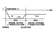
本実施形態は、車間距離情報に基づき、運転者の減速意図に応答して、自動変速機のダウンシフト制御を行って減速制御を行うものについての変速段の決定方法に関する。本実施形態では、図9及び図10に示すように、制御実施領域が二つに分けられる。その一つは、ダウンシフトの開始(本制御の開始)から適正相対車速になるまでの間の領域Aである。もう一つは、適正相対車速になった以降の領域Bである。 The present embodiment relates to a method for determining a gear position for performing a downshift control of an automatic transmission in response to a driver's intention to decelerate based on the inter-vehicle distance information. In the present embodiment, as shown in FIGS. 9 and 10, the control execution area is divided into two. One of them is a region A from the start of downshift (start of this control) to the appropriate relative vehicle speed. The other is the area B after the appropriate relative vehicle speed is reached.
前者の領域Aでは、車間距離・相対車速により目標変速段が決定され、後者の領域Bでは、道路勾配・前車加速度により目標変速段が決定される。領域A,Bが切り替わるタイミングで目標変速段を切り替える。これにより、車間距離が詰まったことによる減速、及び相対車速が適正になった後の追従走行のそれぞれに対応できる変速段が設定されることができ、運転者のブレーキやアクセル操作による車間距離調整の負荷が低減される。 In the former area A, the target shift speed is determined by the inter-vehicle distance and relative vehicle speed, and in the latter area B, the target shift speed is determined by the road gradient and the front vehicle acceleration. The target shift speed is switched at the timing when the areas A and B are switched. As a result, it is possible to set a gear stage that can respond to each of deceleration due to clogging of the inter-vehicle distance and follow-up traveling after the relative vehicle speed becomes appropriate, and adjustment of the inter-vehicle distance by the driver's brake or accelerator operation. Load is reduced.
本実施形態の構成としては、以下に詳述するように、自車と前方の車両との車間距離を計測できる手段と、上記車間距離の情報と運転者の減速意図に基づいて、自動変速機(AT、CVT、ハイブリッド車に搭載されたAT)の変速制御を行う減速制御手段と、走行道路の勾配を計測又は推定できる手段が前提となる。 As described in detail below, the configuration of this embodiment includes an automatic transmission based on means for measuring an inter-vehicle distance between the host vehicle and a preceding vehicle, information on the inter-vehicle distance, and the driver's intention to decelerate. It is premised on deceleration control means for performing shift control of (AT, CVT, AT mounted on a hybrid vehicle) and means capable of measuring or estimating the gradient of the traveling road.
図2において、符号10は自動変速機、40はエンジンである。自動変速機10は、電磁弁121a、121b、121cへの通電/非通電により油圧が制御されて6段変速が可能である。図2では、3つの電磁弁121a、121b、121cが図示されるが、電磁弁の数は3に限定されない。電磁弁121a、121b、121cは、制御回路130からの信号によって駆動される。
In FIG. 2,
スロットル開度センサ114は、エンジン40の吸気通路41内に配置されたスロットルバルブ43の開度を検出する。エンジン回転数センサ116は、エンジン40の回転数を検出する。車速センサ122は、車速に比例する自動変速機10の出力軸120cの回転数を検出する。シフトポジションセンサ123は、シフトポジションを検出する。パターンセレクトスイッチ117は、変速パターンを指示する際に使用される。加速度センサ90は、車両の減速度(減速加速度)を検出する。車間距離計測部100は、車両前部に搭載されたレーザーレーダーセンサ又はミリ波レーダーセンサなどのセンサを有し、先行車両との車間距離を計測する。路面μ検出・推定部115は、路面の摩擦係数μ、又は滑りやすさを検出、あるいは推定する。
The
道路勾配計測・推定部118は、CPU131の一部として設けられることができる。道路勾配計測・推定部118は、加速度センサ90により検出された加速度に基づいて、道路勾配を計測又は推定するものであることができる。また、道路勾配計測・推定部118は、平坦路での加速度を予めROM133に記憶させておき、実際に加速度センサ90により検出した加速度と比較して道路勾配を求めるものであることができる。
The road gradient measurement /
制御回路130は、スロットル開度センサ114、エンジン回転数センサ116、車速センサ122、シフトポジションセンサ123、加速度センサ90の各検出結果を示す信号を入力し、また、パターンセレクトスイッチ117のスイッチング状態を示す信号を入力し、また、路面μ検出・推定部115による検出又は推定の結果を示す信号を入力し、また、車間距離計測部100による計測結果を示す信号を入力する。
The
制御回路130は、周知のマイクロコンピュータによって構成され、CPU131、RAM132、ROM133、入力ポート134、出力ポート135、及びコモンバス136を備えている。入力ポート134には、上述の各センサ114、116、122、123、90からの信号、上述のスイッチ117からの信号、路面μ検出・推定部115及び車間距離計測部100のそれぞれからの信号が入力される。出力ポート135には、電磁弁駆動部138a、138b、138cが接続されている。
The
ROM133には、予め図1のフローチャートに示す動作(制御ステップ)が格納されているとともに、自動変速機10のギヤ段を変速するための変速マップ及び変速制御の動作(図示せず)が格納されている。制御回路130は、入力した各種制御条件に基づいて、自動変速機10の変速を行う。
The
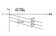
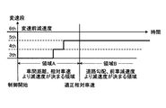
次に、図9を参照して、本実施形態におけるダウンシフト量の考え方について説明する。図9は、車間距離情報に基づく追従制御が行われる際に自動変速機の変速制御がなされることで車両に作用する減速度を示す図である。 Next, the concept of the downshift amount in this embodiment will be described with reference to FIG. FIG. 9 is a diagram illustrating the deceleration acting on the vehicle by performing the shift control of the automatic transmission when the follow-up control based on the inter-vehicle distance information is performed.
図9において、縦軸は加速度、横軸は時間である。変速前減速度501は、本実施形態の変速制御が開始される前の減速度であり、現状のギヤ段により得られるエンジンブレーキ力に対応する減速度である。目標減速度305とは、自車に対してその目標減速度305に基づく減速制御が行われたときに、前方車両との関係が目標の車間距離や相対車速になるような値(減速加速度)である。目標減速度305は、リアルタイムで求められることができる。また、目標減速度305は、所定の判断がなされたときに再度求められることができる。
In FIG. 9, the vertical axis represents acceleration and the horizontal axis represents time. The pre-shift deceleration 501 is a deceleration before the shift control of the present embodiment is started, and is a deceleration corresponding to the engine braking force obtained by the current gear stage. The
第1変速後減速度503aは、相対車速が適正になる前の変速制御によりダウンシフトされた後の変速段により発生する減速度である。第2変速後減速度503bは、相対車速が適正になった後の変速制御によりダウンシフトされた後の変速段により発生する減速度である。
The
図9において、自動変速機の変速制御が開始されて、相対車速が適正になる前の変速制御によりダウンシフトされると、自車に作用する減速度は、変速前減速度501から、第1変速後減速度503aまで増大する。これにより、制御開始時点よりも車間距離が大きくされ、相対車速が小さくなり、やがて、相対車速が適正値となる。 In FIG. 9, when the shift control of the automatic transmission is started and the downshift is performed by the shift control before the relative vehicle speed becomes appropriate, the deceleration acting on the host vehicle is changed from the deceleration 501 before the shift to the first. The deceleration increases after shifting to 503a. As a result, the inter-vehicle distance is made larger than that at the start of control, the relative vehicle speed is reduced, and the relative vehicle speed eventually becomes an appropriate value.
そして、相対車速が適正になった後の変速制御によりダウンシフトされると、自車に作用する減速度は、第1変速後減速度503aから、第2変速後減速度503bまで減少する。相対車速が適正値となる前の領域Aは、自車と前方車両との間の相対車速を小さくしている領域である。相対車速が適正になった後の領域Bは、相対車速が所定の値になった後に、前方車両に自車が追従している領域である。
When the downshift is performed by the shift control after the relative vehicle speed becomes appropriate, the deceleration acting on the host vehicle decreases from the deceleration after the
上記のように、第2変速後減速度503bの設定(相対車速が適正になった後の変速制御におけるダウンシフト後の変速段の選択)に関しては、車間距離や相対車速が所定の値になった後に、前方車両に自車が追従していく上で、最適な変速段が選択される必要がある。
As described above, regarding the setting of the
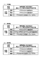
次に、図13を参照して、車間距離又は相対車速が適正な値になった後の自車の状態予測をシチュエーション別に整理する。 Next, referring to FIG. 13, the state prediction of the host vehicle after the inter-vehicle distance or the relative vehicle speed becomes an appropriate value is organized by situation.
(1)走行道路が平坦路である場合
走行道路が平坦路である場合には、車間距離又は相対車速が適正な値になった後に、前方車両が定常運転又は加速すると、自車は、アクセルをONにして前方車両に対する追従走行を行うと予想される。アクセルがONにされると、車間距離情報に基づく減速制御の実施が停止され、通常一般の変速マップに従う変速に復帰するため、第2変速後減速度503bの選択に際して、特別な配慮は不要である。一方、前方車両が減速すると、その前方車両の車速に合わせるべく、自車は、アクセルをOFFのままブレーキをONにすると思われる。そのため、前方車両が減速した場合には、第2変速後減速度503bの設定に関して特に配慮する必要がある。
(1) When the driving road is a flat road When the driving road is a flat road, if the vehicle ahead is steady driving or accelerating after the inter-vehicle distance or relative vehicle speed has reached an appropriate value, It is expected that the vehicle will follow and follow the vehicle ahead. When the accelerator is turned on, the deceleration control based on the inter-vehicle distance information is stopped and the shift to the normal shift map is resumed. Therefore, no special consideration is required when selecting the
(2)走行道路が降坂路である場合
走行道路が降坂路である場合には、車間距離又は相対車速が適正な値になった後に、前方車両が定常運転すると、自車は、アクセルをOFFにして前方車両に対する追従走行を行うと予想される。また、前方車両が加速すると、自車は、アクセルをOFF又はアクセルをONにして前方車両に対する追従走行を行うと予想される。また、前方車両が減速すると、その前方車両の車速に合わせるべく、自車は、アクセルをOFFのままブレーキをONにすると思われる。以上のことから、前方車両が定常運転、加速又は減速した場合には、第2変速後減速度503bの設定に関して特に配慮する必要がある。
(2) When the traveling road is a downhill road When the traveling road is a downhill road, the vehicle turns off the accelerator when the vehicle ahead operates normally after the inter-vehicle distance or relative vehicle speed has reached an appropriate value. Thus, it is expected to follow the vehicle ahead. Further, when the preceding vehicle accelerates, the host vehicle is expected to follow the preceding vehicle with the accelerator turned off or the accelerator turned on. Further, when the preceding vehicle decelerates, it is considered that the own vehicle turns on the brake while keeping the accelerator off in order to match the vehicle speed of the preceding vehicle. From the above, when the front vehicle is in steady operation, accelerated or decelerated, it is necessary to give special consideration to the setting of the
(3)走行道路が登坂路である場合
走行道路が登坂路である場合には、車間距離又は相対車速が適正な値になった後に、前方車両が定常運転又は加速すると、自車は、アクセルをONにして前方車両に対する追従走行を行うと予想される。アクセルがONにされると、車間距離情報に基づく減速制御の実施が停止され、通常一般の変速マップに従う変速に復帰するため、変速後減速度503の選択に際して、特別な配慮は不要である。一方、前方車両が減速すると、その前方車両の車速に合わせるべく、自車は、アクセルをOFFのままブレーキをONにすると思われる。そのため、前方車両が減速した場合には、第2変速後減速度503bの設定に関して特に配慮する必要がある。
(3) When the traveling road is an uphill road When the traveling road is an uphill road, if the front vehicle is in steady operation or accelerates after the inter-vehicle distance or relative vehicle speed has reached an appropriate value, It is expected that the vehicle will follow and follow the vehicle ahead. When the accelerator is turned on, the execution of the deceleration control based on the inter-vehicle distance information is stopped, and the shift to the normal shift map is resumed. Therefore, no special consideration is required when selecting the deceleration 503 after the shift. On the other hand, when the preceding vehicle decelerates, it is considered that the own vehicle turns on the brake while keeping the accelerator off in order to match the vehicle speed of the preceding vehicle. Therefore, when the preceding vehicle decelerates, it is necessary to pay particular attention to the setting of the deceleration after the
図13の上記(1)〜(3)の自車の状態予想結果から、相対車速が適正値になった後のエンジンブレーキ力の大きさに関して特別な配慮が必要であるのは、主に、降坂路である場合と、前方車両が減速した場合であることが分かる。即ち、図13の網掛けで示したケースは、アクセル全閉で前方車両に追従していく場面であるため、それらのケースにおいて適切な減速度が発生するような変速段が選択されることが必要である。 From the above (1) to (3) state prediction results of FIG. 13, the special consideration is necessary regarding the magnitude of the engine braking force after the relative vehicle speed becomes an appropriate value. It turns out that it is a case where it is a downhill road and a front vehicle decelerates. That is, the cases shown by the shaded area in FIG. 13 are scenes in which the accelerator is fully closed and the vehicle follows the vehicle ahead. Therefore, in these cases, a gear stage that generates an appropriate deceleration may be selected. is necessary.
図1及び図2を参照して、本実施形態の動作を説明する。 The operation of this embodiment will be described with reference to FIGS.
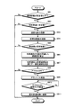
[ステップS1]
まず、図1のステップS1に示すように、制御回路130では、車間距離計測部100から入力した車間距離を示す信号に基づいて、自車と前方の車両との車間距離が所定値以下であるか否かを判定する。ステップS1の結果、車間距離が所定値以下であると判定されれば、ステップS2に進む。一方、車間距離が所定値以下であると判定されなければ、本制御フローは終了する。
[Step S1]
First, as shown in step S <b> 1 of FIG. 1, in the
制御回路130では、車間距離が所定値以下であるか否かを直接的に判定する代わりに、車間距離が所定値以下に詰まったことが判るパラメータ、例えば衝突時間(車間距離/相対車速)、車間時間(車間距離/自車速)、それらの組み合わせなどにより、間接的に車間距離が所定値以下であるか否かを判定してもよい。
In the
[ステップS2]
ステップS2では、制御回路130により、スロットル開度センサ114からの信号に基づいて、アクセルがOFFの状態か否かが判定される。ステップS2では、運転者による減速意図が確認される。ステップS2の結果、アクセルがOFFの状態であると判定されれば、ステップS3に進む。ステップS3から車両の追従制御が開始される。一方、アクセルがOFFの状態であると判定されなければ、本制御フローは終了する。
[Step S2]
In step S2, the
[ステップS3]
ステップS3では、制御回路130により、車間時間及び相対車速に基づいて、変速制御によるダウンシフト先としての変速段が決定される。ステップS3において、変速段は、予めROM133に記憶された、車間時間・相対車速による変速段決定マップ(図3)を参照して求められる。図3に示すように、変速段は、自車と前方車両との相対車速[km/h]と車間時間[sec]に基づいて求められる。
[Step S3]
In step S <b> 3, the
図3において、例えば、相対車速が−40[km/h]であって、車間時間が1.0[sec]であるときの変速段は3速である。自車と前方車両との関係が安全な相対車速や車間距離に近づく程、変速段は、高い変速段として(減速しないように)設定される。即ち、変速段は、自車と前方車両との距離が十分に確保される程、図3のマップの右上側の高い変速段として求められ、自車と前方車両とが接近している程、同マップの左下側の低い変速段として求められる。なお、図10の例では、車間距離、相対車速により減速度が決まる領域Aにおける変速段は、3速として示されている。 In FIG. 3, for example, when the relative vehicle speed is −40 [km / h] and the inter-vehicle time is 1.0 [sec], the gear position is the third speed. As the relationship between the host vehicle and the preceding vehicle approaches a safe relative vehicle speed or inter-vehicle distance, the gear position is set to a higher gear position (so as not to decelerate). That is, the shift speed is calculated as a higher shift speed on the upper right side of the map of FIG. 3 as the distance between the own vehicle and the preceding vehicle is sufficiently secured, and the closer the own vehicle and the preceding vehicle are, It is obtained as a lower gear position on the lower left side of the map. In the example of FIG. 10, the gear position in the region A where the deceleration is determined by the inter-vehicle distance and the relative vehicle speed is shown as the third speed.
上記では、変速段決定マップ(図3)を用いて、変速段を決定する方法について説明したが、上記方法に代えて、以下に説明するような方法により、変速段を決定することもできる。 In the above description, the method for determining the shift speed using the shift speed determination map (FIG. 3) has been described. However, instead of the above method, the shift speed can also be determined by a method described below.
即ち、制御回路130により、自動変速機10による目標減速度(以下、変速段目標減速度)が求められ、その変速段目標減速度に基づいて、自動変速機10の変速制御(シフトダウン)に際して選択すべき変速段が決定される。以下、この方法の内容を(1)、(2)に項分けして説明する。
That is, the
(1)まず、変速段目標減速度を求める。
変速段目標減速度は、自動変速機10の変速制御により得ようとするエンジンブレーキ力(減速加速度)に対応したものである。変速段目標減速度は、後述する最大目標減速度以下の値として設定される。変速段目標減速度の求め方としては、以下の3つの方法が考えられる。
(1) First, the gear position target deceleration is obtained.
The gear stage target deceleration corresponds to the engine braking force (deceleration acceleration) to be obtained by the shift control of the
まず、変速段目標減速度の第1の求め方について説明する。
変速段目標減速度は、図4の目標減速度マップにより求めた最大目標減速度に、0よりも大きく1以下の係数を乗算した値として設定する。
First, a first method for obtaining the speed target deceleration will be described.
The gear stage target deceleration is set as a value obtained by multiplying the maximum target deceleration obtained by the target deceleration map of FIG. 4 by a coefficient greater than 0 and 1 or less.
目標減速度は、予めROM133に記憶された目標減速度マップ(図4)を参照して求められる。図4に示すように、目標減速度は、自車と前方車両との相対車速[km/h]と車間時間[sec]に基づいて求められる。なお、ここで、車間時間は、上記の通り、車間距離/自車速である。
The target deceleration is obtained with reference to a target deceleration map (FIG. 4) stored in advance in the
図4において、例えば、相対車速が−40[km/h]であって、車間時間が1.0[sec]であるときの目標減速度は−0.26(G)である。自車と前方車両との関係が安全な相対車速や車間距離に近づく程、目標減速度は、小さな値として(減速しないように)設定される。即ち、目標減速度は、自車と前方車両との距離が十分に確保される程、図4の目標減速度マップの右上側の小さな値として求められ、自車と前方車両とが接近している程、同目標減速度マップの左下側の大きな値として求められる。 In FIG. 4, for example, when the relative vehicle speed is −40 [km / h] and the inter-vehicle time is 1.0 [sec], the target deceleration is −0.26 (G). The target deceleration is set to a smaller value (so as not to decelerate) as the relationship between the host vehicle and the preceding vehicle approaches a safe relative vehicle speed or inter-vehicle distance. That is, the target deceleration is obtained as a small value on the upper right side of the target deceleration map in FIG. 4 as the distance between the host vehicle and the preceding vehicle is sufficiently secured. The higher the value, the larger the value on the lower left side of the target deceleration map.
ここで求められる目標減速度は、減速制御の開始条件(ステップS1及びS2)が成立した後、変速制御(ステップS4)が実際に実行される前の時点(減速制御開始時点)での目標減速度として、特に、最大目標減速度と称される。即ち、目標減速度は、後述するように、減速制御の途中段階においてもリアルタイムに求められることが可能であるため、変速制御が実際に実行された後(実行継続中)に求められる目標減速度と区別する意味で、ここで求められる目標減速度は、特に、最大目標減速度と称される。 The target deceleration obtained here is the target deceleration at the time (deceleration control start time) before the speed change control (step S4) is actually executed after the deceleration control start condition (steps S1 and S2) is satisfied. The speed is particularly referred to as the maximum target deceleration. That is, the target deceleration can be obtained in real time even in the middle of the deceleration control, as will be described later. Therefore, the target deceleration obtained after the shift control is actually executed (during execution). The target deceleration obtained here is particularly referred to as the maximum target deceleration.
例えば、最大目標減速度が−0.26Gである場合には、例えば0.5の係数を乗算してなる値である、−0.13Gが変速段目標減速度として設定されることができる。 For example, when the maximum target deceleration is −0.26 G, for example, −0.13 G, which is a value obtained by multiplying a coefficient of 0.5, can be set as the shift stage target deceleration.
次に、変速段目標減速度の第2の求め方について説明する。
予めROM133に、変速段目標減速度マップ(図5)が登録されている。図5の変速段目標減速度マップが参照されて、変速段目標減速度が求められる。図5に示すように、変速段目標減速度は、図4の目標減速度と同様に、自車と前方車両との相対車速[km/h]と車間時間[sec]に基づいて求められる。例えば、上記例の場合と同様に、相対車速が−40[km/h]であって、車間時間が1.0[sec]である場合には、−0.15Gが変速段目標減速度として求められる。図4及び図5から明らかなように、相対車速が大きく急激に接近する場合、車間時間が短い場合、あるいは車間距離が短い場合は、早期に車間距離を適正な状態にする必要があるため、減速度をより大きくする必要がある。また、このことから、上記の状況ではより低速段が選択されることになる。
Next, a second method for obtaining the shift speed target deceleration will be described.
A gear stage target deceleration map (FIG. 5) is registered in the
次に、変速段目標減速度の第3の求め方について説明する。
まず、本制御開始前の自動変速機10の現状のギヤ段のアクセルOFF時のエンジンブレーキ力(減速G)を求める(以下、変速前減速度501と称する)。予めROM133に各ギヤ段減速度マップ(図6)が登録されている。図6の各ギヤ段減速度マップが参照されて、変速前減速度501が求められる。図6に示すように、変速前減速度501は、ギヤ段と自動変速機10の出力軸120cの回転数NOに基づいて求められる。例えば、現状ギヤ段が5速で出力回転数が1000[rpm]であるときには、変速前減速度501は−0.04Gである。なお、図10の例では、現状ギヤ段は、5速として示されている。
Next, a third method for obtaining the speed target deceleration will be described.
First, the engine braking force (deceleration G) at the time of acceleration OFF of the current gear stage of the
なお、変速前減速度501は、車両のエアコン作動の有無やフューエルカットの有無などの諸状況に応じて、各ギヤ段減速度マップにより求めた値を補正してもよい。また、車両のエアコン作動の有無やフューエルカットの有無などの諸状況毎に、複数の各ギヤ段減速度マップをROM133に用意しておき、それらの諸状況に応じて使用する各ギヤ段減速度マップを切り換えてもよい。
Note that the pre-shift deceleration 501 may be corrected by a value obtained from each gear speed deceleration map in accordance with various situations such as whether the vehicle is operating an air conditioner or whether there is a fuel cut. In addition, a plurality of gear speed deceleration maps are prepared in the
次いで、変速前減速度501と最大目標減速度との間の値として、変速段目標減速度が設定される。即ち、変速段目標減速度は、変速前減速度501よりも大きく、最大目標減速度以下の値として求められる。変速段目標減速度と変速前減速度501及び最大目標減速度との関係の一例を図7に示す。 Next, the speed target deceleration is set as a value between the pre-shift deceleration 501 and the maximum target deceleration. That is, the speed target deceleration is obtained as a value that is greater than the pre-shift deceleration 501 and less than or equal to the maximum target deceleration. An example of the relationship between the speed target deceleration, the pre-shift deceleration 501 and the maximum target deceleration is shown in FIG.
変速段目標減速度は、以下の式により求められる。
変速段目標減速度=(最大目標減速度−変速前減速度501)×係数+変速前減速度501
上記式において、係数は0より大きく1以下の値である。
The speed target deceleration is obtained by the following equation.
Shift target deceleration = (maximum target deceleration−deceleration before shifting 501) × coefficient + deceleration before shifting 501
In the above formula, the coefficient is a value greater than 0 and less than or equal to 1.
上記例では、最大目標減速度=−0.26G、変速前減速度501=−0.04Gであり、係数を0.5と設定して計算すると、変速段目標減速度は−0.15Gとなる。 In the above example, maximum target deceleration = −0.26G, pre-shift deceleration 501 = −0.04G, and calculation is performed with the coefficient set to 0.5, the shift speed target deceleration is −0.15G. Become.
上記のように、変速段目標減速度の第1及び第3の求め方では、係数が用いられたが、その係数の値は、理論上から求まる値ではなく、各種条件から適宜設定可能な適合値である。即ち、例えば、スポーツカーでは、減速すべきときには相対的に大きな減速度が好まれるため、上記係数の値を大きな値に設定することができる。また、同じ車両であっても、車速やギヤ段に応じて、上記係数の値を可変に制御することができる。運転者の操作に対する車両の応答性を高め、きびきびとした車両走行を意図した所謂スポーツモードと、運転者の操作に対する車両の応答性をゆったりとしたものとして、低燃費となるような車両走行を意図した所謂ラグジュアリーモードやエコノミーモードと呼ばれるモードが選択可能な車両の場合、スポーツモード選択時には、変速段目標減速度はラグジュアリーモードやエコノミーモードよりも大きな変速段変化が起きるように設定される。 As described above, a coefficient is used in the first and third methods for determining the target gear position deceleration, but the value of the coefficient is not a theoretical value, but can be appropriately set from various conditions. Value. That is, for example, in a sports car, a relatively large deceleration is preferred when decelerating, and therefore the value of the coefficient can be set to a large value. Further, even for the same vehicle, the value of the coefficient can be variably controlled according to the vehicle speed and the gear stage. The vehicle responsiveness to the driver's operation is improved, the so-called sport mode intended for sharp vehicle driving, and the vehicle's responsiveness to the driver's operation is relaxed, so that the vehicle travels with low fuel consumption. In the case of a vehicle in which a mode called an intended so-called luxury mode or economy mode can be selected, when the sport mode is selected, the gear stage target deceleration is set such that a larger gear stage change occurs than in the luxury mode or the economy mode.
(2)次に、上記(1)で求めた変速段目標減速度に基づいて、自動変速機10の変速制御に際して選択すべき変速段が決定される。予めROM133に、図8に示すようなアクセルOFF時の各ギヤ段の車速毎の減速Gを示す車両特性のデータが登録されている。
(2) Next, based on the shift speed target deceleration obtained in the above (1), the shift speed to be selected in the shift control of the
ここで、上記例と同様に、出力回転数が1000[rpm]であり、変速段目標減速度が−0.15Gである場合を想定すると、図8において、出力回転数が1000[rpm]のときの車速に対応し、かつ変速段目標減速度の−0.15Gに最も近い減速度となるギヤ段は、3速であることが判る。これにより、上記例の場合、ステップS3では、選択すべきギヤ段は、3速であると決定される。 As in the above example, assuming that the output rotational speed is 1000 [rpm] and the gear stage target deceleration is −0.15 G, the output rotational speed is 1000 [rpm] in FIG. It can be seen that the gear stage corresponding to the vehicle speed at the time and having the closest deceleration to the gear stage target deceleration of -0.15G is the third speed. Thus, in the case of the above example, in step S3, the gear to be selected is determined to be the third speed.
なお、ここでは、変速段目標減速度に最も近い減速度となるギヤ段を選択すべきギヤ段として選択したが、選択すべきギヤ段は、変速段目標減速度以下(又は以上)の減速度であって変速段目標減速度に最も近い減速度となるギヤ段を選択してもよい。ステップS3の次にステップS4が実行される。 Here, the gear stage that is the closest to the gear stage target deceleration is selected as the gear stage to be selected, but the gear stage to be selected is a deceleration below (or above) the gear stage target deceleration. In this case, the gear stage that is the closest to the gear stage target deceleration may be selected. Step S4 is executed after step S3.
[ステップS4]
ステップS4では、制御回路130により、変速制御が開始される。即ち、ステップS3で決定された選択すべきギヤ段(ステップS3の上記例では、3速)に変速制御される。それに伴い、エンジンブレーキ力が増加する。ステップS4の次に、ステップS5が実行される。図10の例では、制御開始前のギヤ段が5速であり、制御が開始されると、上記ステップS3において車間時間、相対車速に基づいて決定された、3速の変速段に変速制御される。
[Step S4]
In step S4, the
[ステップS5]
ステップS5では、制御回路130により、相対車速が予め設定された所定値より小さいか否かが判定される。ステップS5の判定の結果、相対車速が所定値よりも小さければ、ステップS6に進み、そうでなければ、相対車速が所定値より小さくなるまでステップS5が繰り返し行われる。ステップS5において、相対車速が所定値よりも小さいと判定されると、図10において、相対車速が適正値であると判定された後の領域Bに入る。
[Step S5]
In step S5, the
なお、ステップS5は、車間時間、衝突時間、相対車速などの前車との関係を示すパラメータに基づいて判定してもよいし、これらのパラメータを適宜組み合わせることにより判定してもよい。 Note that step S5 may be determined based on parameters indicating the relationship with the preceding vehicle such as inter-vehicle time, collision time, and relative vehicle speed, or may be determined by appropriately combining these parameters.
[ステップS6]
ステップS6では、制御回路130の道路勾配計測・推定部118により、自車が走行する道路の勾配が求められる。ROM133には、上述したように、図6に示すような各ギヤ段でのアクセル全閉時の減速度が記述された各ギヤ段減速度マップが格納されている。図6に示すように、そのマップには、平坦路における各ギヤ段の車速毎の減速度が記述されている。道路勾配計測・推定部118は、予めROM133にマップとして記憶された平坦路での加速度と、実際に加速度センサ90により検出した加速度とを比較して、実加速度がマップの加速度よりも大きい場合には降坂路であり、実加速度がマップの加速度よりも小さい場合には登坂路である。この場合、実加速度とマップの加速度の偏差0.01G≒道路勾配1%に対応する。
[Step S6]
In step S6, the road gradient measuring /
いま、5速の変速段で自動変速機10の出力軸120cの回転数Noが1000rpmで走行しているとする。その場合の実加速度は、−0.06Gであったとする。同じ条件で、マップ(図6)には平坦路である場合の加速度として、−0.04Gと記述されている。この場合には、道路勾配2%の降坂路であると計測又は推定される。ステップS6の次には、ステップS7が行われる。
It is assumed that the rotation speed No of the
[ステップS7]
ステップS7では、制御回路130により、前方車両の加速度が求められる。前方車両と自車との車間距離を2回微分することにより相対加速度が求められ、その相対加速度と自車の加速度との差をとることで、前方車両の加速度が求められる。本例では、例えば前方車両の減速度は、−0.082Gであるとする。ステップS7の次には、ステップS8が行われる。
[Step S7]
In step S7, the acceleration of the vehicle ahead is obtained by the
[ステップS8]
ステップS8では、制御回路130により、上記ステップS6及びステップS7の演算結果に基づいて、自車が走行している道路が降坂路であるか否か、又は前方車両が減速状態にあるか否かが判定される。その判定の結果、自車が走行している道路が降坂路又は前方車両が減速状態である場合には、ステップS9に進み、そうでない場合にはステップS12に進む。
[Step S8]
In step S8, the
[ステップS9]
ステップS9では、制御回路130により、上記ステップS6の演算結果に基づいて、各変速段の道路勾配を考慮した減速度が算出される。ステップS9では、ステップS6にて求められた道路勾配分だけ図6のマップに記述された各減速度の値を補正する。その補正に際して、上記ステップS6において求められた道路勾配1%=0.01Gで近似することができ、登坂路では正の値、降坂路では負の値として加算される。
[Step S9]
In step S9, the
上記例では、道路勾配が2%の降坂路であると判定されているため、ステップS9では、図6のマップに記述された各減速度の値には、−0.02Gがそれぞれ加算される。例えば、自動変速機10の出力軸120cの回転数Noが2000rpmである各変速段の減速度は、5速が−0.07G、4速が−0.08G、3速が−0.09Gとされる。なお、道路勾配が無い平坦路であり、上記ステップS6にて道路勾配が0%であるとされた場合には、ステップS9の結果としての各変速段の減速度は、図6のマップに記述された値と同じである。ステップS9の次に、ステップS10が行われる。
In the above example, since it is determined that the road gradient is 2% downhill, -0.02G is added to each deceleration value described in the map of FIG. 6 in step S9. . For example, the deceleration of each shift stage in which the rotation speed No of the
[ステップS10]
ステップS10では、制御回路130により、相対車速が適正になった後の変速制御によるダウンシフト先として、最適な変速段が選択される。その選択された変速段による減速度が第2変速後減速度503bである(図9)。ここで、選択される最適な変速段とは、“上記ステップS9で求められた道路勾配が考慮された変速段の減速度が、上記ステップS7にて求められた前方車両の減速度以上の変速段である”という条件を満たす変速段のうち、一番低速段である。
[Step S10]
In step S10, the
上記例では、上記ステップS7にて求められた前方車両の減速度は、−0.082Gである。上記ステップS9で求められた道路勾配が考慮された変速段の減速度が、−0.082G以上である変速段は、4速、5速になり、それらのうちで一番低速段である変速段は4速である。そのため、本例では、4速の変速段が選択される。なお、図10の例では、道路勾配、前車減速度より減速度が決定される領域Bの変速段は、4速として示されている。 In the above example, the deceleration of the forward vehicle obtained in step S7 is -0.082G. The gears having a deceleration of -0.082G or more in consideration of the road gradient obtained in step S9 are the fourth gear and the fifth gear, and the gear speed that is the slowest among them is the gear. The stage is 4th speed. Therefore, in this example, the fourth speed is selected. In the example of FIG. 10, the gear position in the region B where the deceleration is determined based on the road gradient and the front vehicle deceleration is shown as the fourth speed.
なお、有段の自動変速機10である場合には、上記のような関係を満たす変速段のうちの一番低い変速段が選択されるのに対し、無段変速機である場合には、道路勾配を加味した変速比の減速度が、前方車両の減速度と等しい変速比が選択されることができる。ステップS10の次に、ステップS11が行われる。
In the case of the stepped
[ステップS11]
ステップS11では、制御回路130により、変速制御が行われる。即ち、ステップS10で決定された選択すべきギヤ段(ステップS10の上記例では、4速)に変速制御される。それに伴い、エンジンブレーキ力が減少する。本実施形態によれば、相対車速が適正値になった後も、道路勾配、前車減速度より決定される変速段に変速制御されるため、従来技術のように、降坂路などにおいて制御ハンチングが発生することが最小限に抑制される。ステップS11の次に、ステップS12が実行される。
[Step S11]
In step S <b> 11, shift control is performed by the
[ステップS12]
ステップS12では、制御回路130により、アクセルがONにされ、そのアクセルのONに応答してスタートした復帰タイマーカウント値が所定値以上であるか否かが判定される。カウント値が所定値以上でなければ、ステップS12に戻る。カウント値が所定値以上になれば、ステップS13に進む。
[Step S12]
In step S12, the
[ステップS13]
ステップS13では、制御回路130による、変速制御(ダウンシフト制御)が終了し、予めROM133に格納された通常の変速マップ(変速線)に従いアクセル開度と車速に基づき決定される変速段に復帰する。ステップS13が実施されると、本制御フローは終了する。
[Step S13]
In step S13, the shift control (downshift control) by the
図13を参照して説明したように、走行道路が降坂路である、又は前方車両が減速状態である場合以外(ステップS8−N)には、相対車速が適正値になった後においてアクセルがONにされて、変速点制御が解除されて、通常の変速マップに従う変速に復帰する可能性が高い。即ち、走行道路が降坂路である、又は前方車両が減速状態である場合以外(ステップS8−N)には、変速点制御の状態のまま、図9及び図10の領域Bに入る可能性は少ないことから、変速点制御により発生させる領域Bにおける減速度の設定(領域Bにおけるダウンシフト先の変速段の選択)に関して、道路勾配や前方車両の減速度のような前方車両との車間距離や相対車速に影響を与えるパラメータを特に考慮する必要はない。そのため、領域Bには行った後にも、領域Aの変速段が切り替えられることが無い(ステップS8−N)。 As described with reference to FIG. 13, except when the traveling road is a downhill road or the preceding vehicle is in a decelerating state (step S8-N), after the relative vehicle speed has reached an appropriate value, the accelerator is There is a high possibility that the shift point control is canceled when the switch is turned on and the shift to the shift according to the normal shift map is restored. That is, there is a possibility of entering the region B in FIG. 9 and FIG. 10 while maintaining the shift point control except when the traveling road is a downhill road or when the preceding vehicle is in a decelerating state (step S8-N). Since there are few, regarding the setting of the deceleration in the region B generated by the shift point control (selection of the downshift destination gear in the region B), the inter-vehicle distance from the preceding vehicle such as the road gradient and the deceleration of the preceding vehicle, It is not necessary to take into consideration parameters that affect the relative vehicle speed. For this reason, the shift speed of the region A is not switched even after performing the operation in the region B (step S8-N).
本実施形態においては、相対車速が適正になる時点の前後で2つの領域A,Bに分けられている。領域Aでは、変速段は、車間時間と相対車速に基づいて決定される(ステップS3)が、領域Bでは、相対車速が適正になった後の追従走行に際しての運転者のブレーキやアクセル操作による車間距離調整が低減されるべく、走行道路が降坂路である場合、又は前方車両が減速している場合には、自車が走行する降坂路の勾配を考慮した変速段による減速度と、前方車両の減速度とに基づいて、変速段が選択される(ステップS8−Y、ステップS9、ステップS10)。 In the present embodiment, the area is divided into two areas A and B before and after the relative vehicle speed becomes appropriate. In region A, the gear position is determined based on the inter-vehicle time and the relative vehicle speed (step S3), but in region B, it is determined by the driver's brake or accelerator operation during follow-up travel after the relative vehicle speed becomes appropriate. In order to reduce the inter-vehicle distance adjustment, when the road is a downhill road or when the vehicle ahead is decelerating, the deceleration by the shift stage considering the slope of the downhill road where the vehicle travels, A gear position is selected based on the deceleration of the vehicle (step S8-Y, step S9, step S10).
なお、ステップS10では、実際には、3〜5速の変速段の中から変速段が選択されることが好ましい。また、ステップS10において、最大目標減速度よりも大きな減速度を発生する変速段は選択されない。 In step S10, actually, it is preferable to select a gear position from among the third to fifth gear positions. In step S10, a gear stage that generates a deceleration larger than the maximum target deceleration is not selected.
以上に述べた本実施形態によれば、以下の効果を奏することができる。
車間距離情報に基づいて、ダウンシフトにより減速制御を行う場合、目標の車間距離や車速になるような目標変速段を設定する。この目標変速段への変速制御により、相対車速が適正値になる。
According to this embodiment described above, the following effects can be obtained.
When deceleration control is performed by downshifting based on the inter-vehicle distance information, a target shift stage is set such that the target inter-vehicle distance and the vehicle speed are obtained. By the shift control to the target shift stage, the relative vehicle speed becomes an appropriate value.
相対車速が適正になった後のダウンシフトによるエンジンブレーキ力(減速度)に関しては、降坂路走行時又は前方車両が減速時には、アクセル全閉で前方車両に追従可能な変速段が設定される。即ち、降坂路走行時又は前方車両が減速時には、その道路勾配や前方車両の減速度に基づいて、ダウンシフト先の変速段が選択される。これにより、状況に応じた最適な変速段が選択され、降坂路での制御ハンチングが防止され、ドライバビリティが向上する。 With respect to the engine braking force (deceleration) due to downshifting after the relative vehicle speed becomes appropriate, a gear stage that can follow the front vehicle with the accelerator fully closed is set when traveling downhill or when the front vehicle decelerates. That is, when traveling downhill or when the preceding vehicle decelerates, the downshift destination gear is selected based on the road gradient and the deceleration of the preceding vehicle. As a result, the optimum gear position according to the situation is selected, control hunting on the downhill road is prevented, and drivability is improved.
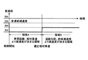
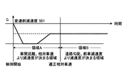
なお、上記の例では、相対車速が適正になる前の領域Aにおける、車間時間、相対車速に基づく変速段の決定は、1回のみ行われた。これに代えて、以下のような動作にしてもよい。即ち、図11及び図12に示すように、領域Aでは、図3のマップ(又は図4〜図8のマップ)を用いて、車間時間、相対車速に応じて、リアルタイムに変速段を更新することができる。減速制御によって、時間の経過と共に減少する車間時間、相対車速に対応した変速段が設定されるため、領域Aの終期においてエンジンブレーキ力が掛かり過ぎることは無い。この場合、領域Aにおいて、予め、領域Bでの変速段を求めておき、領域Aにおいて相対車速の減少に応じてリアルタイムに求められる変速段は、その予め求めておいた領域Bにおける変速段よりも高速段に設定されない(アップシフトされない)ようにガードをかけるのがよい。適正相対車速になる前にアップシフトされて、相対車速になった直後にその変速段からダウンシフトされるのは、運転者に違和感を与え、ドライバビリティの面で良くないためである。 Note that in the above example, the determination of the gear position based on the inter-vehicle time and the relative vehicle speed in the region A before the relative vehicle speed becomes appropriate is performed only once. Instead of this, the following operation may be performed. That is, as shown in FIGS. 11 and 12, in the region A, the gear position is updated in real time according to the inter-vehicle time and the relative vehicle speed using the map of FIG. 3 (or the maps of FIGS. 4 to 8). be able to. Due to the deceleration control, the speed corresponding to the inter-vehicle time and the relative vehicle speed that decrease with the passage of time is set, so that the engine braking force is not excessively applied at the end of the region A. In this case, in the region A, the gear position in the region B is obtained in advance, and the gear step that is obtained in real time in response to the decrease in the relative vehicle speed in the region A is greater than the gear step in the region B that is obtained in advance. It is better to apply a guard so that the high speed stage is not set (not upshifted). The reason for upshifting before reaching the appropriate relative vehicle speed and downshifting from the gear position immediately after reaching the relative vehicle speed is because it gives the driver a sense of incongruity and is not good in terms of drivability.
本実施形態における領域Bでの変速制御の変速段の設定方法としては、以下のように考えることができる。即ち、相対車速が適正値になった後の第2変速後減速度503bは、例えば相対車速がゼロを含む所定の範囲に収まり(維持され)、前方車両への追従走行がエンジンブレーキ力のみで実現されるための値であることが好ましい。この観点から、基本的な考え方としては、第2変速後減速度503b、即ち、相対車速が適正値になった後のダウンシフト先の変速段は、前方車両の減速度と同じ値であるか、又は近い値であることが好ましい。そのため、有段の自動変速機が使用される本実施形態では、前方車両の減速度以下のエンジンブレーキ力を発生させる変速段のうち、前方車両の減速度に最も近いエンジンブレーキ力を発生させる変速段が選択される(ステップS10)。
A method for setting the gear position of the shift control in the region B in the present embodiment can be considered as follows. In other words, the
上記基本的な考え方を更に発展させると、次のようになる。即ち、相対車速が適正値になった後に、車両にエンジンブレーキ力のみが作用している場合において、車両に実際に作用する減速度が前方車両の減速度になるべく近くであることが好ましい。この場合、車両に実際に作用する減速度は、変速段により発生するエンジンブレーキ力のみではなく、仮想的に道路勾配により生じる減速度を加味した値である。そのため、仮想的に道路勾配により生じる減速度を加味した、変速段により発生するエンジンブレーキ力と、前方車両の減速度に基づいて、変速制御の変速段が設定されることとしている(ステップS9、ステップS10)。 Further development of the above basic idea is as follows. That is, when only the engine braking force is applied to the vehicle after the relative vehicle speed reaches an appropriate value, the deceleration actually acting on the vehicle is preferably as close as possible to the deceleration of the preceding vehicle. In this case, the deceleration actually acting on the vehicle is a value that takes into account not only the engine braking force generated by the shift stage but also the deceleration caused by the road gradient virtually. For this reason, the shift stage of the shift control is set based on the engine braking force generated by the shift stage and the deceleration of the preceding vehicle, taking into account the deceleration caused by the road gradient (step S9, Step S10).
更に、本実施形態では、図13に示したように、相対車速が適正値になった後のエンジンブレーキ力を上記考え方(ステップS9、ステップS10)に基づいて決定すべき状況が、走行道路が降坂路である場合と、前方車両が減速時である場合に鑑みて、これらの場合に限って、上記考え方(ステップS9、ステップS10)を適用している。走行道路が降坂路である場合、又は前方車両が減速時である場合以外のケース(ステップS8−N)では、相対車速が適正値に到達した以降も、相対車速が適正値になる前の変速段から変更が無いとしている(ステップS8−N)。 Furthermore, in the present embodiment, as shown in FIG. 13, the situation in which the engine braking force after the relative vehicle speed becomes an appropriate value should be determined based on the above concept (step S9, step S10) Considering the case of a downhill road and the case where the preceding vehicle is decelerating, the above concept (step S9, step S10) is applied only in these cases. In cases other than when the traveling road is a downhill road or when the preceding vehicle is decelerating (step S8-N), the speed change before the relative vehicle speed reaches the appropriate value even after the relative vehicle speed reaches the appropriate value. It is assumed that there is no change from the stage (step S8-N).
ここで、本発明では、上記実施形態に限定されるものではない。例えば、走行道路が降坂路である場合、又は前方車両が減速時である場合以外のケース(ステップS8−N)であっても、上記基本的考え方(ステップS10)、ないしは、上記ステップS9をも含めた考え方(ステップS9、ステップS10)を適用することが可能である。 Here, the present invention is not limited to the above embodiment. For example, even in a case (step S8-N) other than when the traveling road is a downhill road or when the preceding vehicle is decelerating (step S8-N), the basic idea (step S10) or step S9 is also included. It is possible to apply the concept (step S9, step S10) included.
(第2実施形態)
次に、図14を参照して、第2実施形態について説明する。
第2実施形態では、上記第1実施形態との相違点についてのみ説明する。
(Second Embodiment)
Next, a second embodiment will be described with reference to FIG.
In the second embodiment, only differences from the first embodiment will be described.
上記第1実施形態では、前方車両との車間距離、相対車速が適正値になるまでの減速(領域A)が、自動変速機10の変速制御により行われた例について説明した。第2実施形態では、領域Aでの減速は、運転者がフットブレーキの操作により行い、相対車速が適正になった後の領域Bでは、自動変速機10の変速制御が行われる例について説明する。
In the first embodiment, the example in which the deceleration (region A) until the inter-vehicle distance from the preceding vehicle and the relative vehicle speed become appropriate values (region A) is performed by the shift control of the
図14のステップSA1は、図1のステップS1と同様であり、図14のステップSA4は、図1のステップS5と同様である。以下同様に、図14のステップSA5、ステップSA6、ステップSA7、ステップSA8〜ステップSA10、ステップSA12、ステップSA13は、それぞれ、図1のステップS6、ステップS7、ステップS2、ステップS8〜ステップS10、ステップS12、ステップS13と同様である。よって、これらのステップの詳細な説明は、省略する。 Step SA1 in FIG. 14 is the same as step S1 in FIG. 1, and step SA4 in FIG. 14 is the same as step S5 in FIG. Similarly, Step SA5, Step SA6, Step SA7, Step SA8 to Step SA10, Step SA12, and Step SA13 in FIG. 14 are the same as Step S6, Step S7, Step S2, Step S8 to Step S10 in FIG. It is the same as S12 and step S13. Therefore, detailed description of these steps is omitted.
[ステップSA2]
図14に示すように、車間距離が所定値以下である場合(ステップSA1−Y)に、制御回路130により、運転者によってフットブレーキがONにされたか否かが判定される。ブレーキがONにされた場合には、ステップSA3に進み、そうでない場合には、本制御フローはリターンされる。
[Step SA2]
As shown in FIG. 14, when the inter-vehicle distance is equal to or smaller than a predetermined value (step SA1-Y), the
[ステップSA3]
制御回路130により、運転者によってフットブレーキがOFFにされたか否かが判定される。ステップSA3の判定の結果、フットブレーキがOFFにされたと判定されない場合には、そのように判定されるまでステップSA3が繰り返し行われる。
[Step SA3]
The
[ステップSA7]
ステップSA7では、図1のステップS2と同様に、運転者による減速意図が確認される。
[Step SA7]
In step SA7, the driver's intention to decelerate is confirmed as in step S2 of FIG.
[ステップSA11]
ステップSA11では、制御回路130により、ステップSA10で決定された変速段への変速制御が実行される。相対車速が適正値になった後(ステップSA4−Y)に、自動変速機10が道路勾配、前車減速度に基づいて決定された変速段に変速制御される点(ステップSA8〜ステップSA11)は、上記第1実施形態と共通である。
[Step SA11]
In step SA11, the
第2実施形態は、相対車速が適正値になったことが検出された後に、前車に追従走行していくときの変速段の決定方法に関するものである。第2実施形態によれば、相対車速が適正になった後の追従走行に際して、運転者のブレーキやアクセル操作による車間距離調整の負荷が低減される。上記第2実施形態では、領域Aにおける減速が、運転者によるフットブレーキの操作により行われた例について説明したが、領域Aにおける減速の手段については、特に限定されず、例えば、運転者が手動により自動変速機10を低速段に変速する動作(マニュアルシフト)であってもよい。
The second embodiment relates to a method for determining a gear position when the vehicle travels following the front vehicle after it has been detected that the relative vehicle speed has reached an appropriate value. According to the second embodiment, during the follow-up traveling after the relative vehicle speed becomes appropriate, the load of adjusting the inter-vehicle distance by the driver's brake or accelerator operation is reduced. In the second embodiment, the example in which the deceleration in the region A is performed by the driver operating the foot brake has been described. However, the means for the deceleration in the region A is not particularly limited. Thus, an operation of shifting the
(第3実施形態)
次に、図15を参照して、第3実施形態について説明する。
第3実施形態において、上記実施形態と共通する部分についての説明は省略する。
(Third embodiment)
Next, a third embodiment will be described with reference to FIG.
In the third embodiment, descriptions of parts common to the above embodiment are omitted.
第3実施形態は、車間距離が所定値以下であった状態(ステップSB1−Y)から、ブレーキ操作なしで(アクセル操作のみで)、相対車速が所定値より小さくなった後に、前車に追従走行していくときの変速段の決定方法に関するものである。相対車速が適正値になった後(ステップSB2−Y)に、自動変速機10が道路勾配、前車減速度に基づいて決定された変速段に変速制御される点(ステップSB5〜ステップSB9)は、上記第1、第2実施形態と共通である。
In the third embodiment, from the state in which the inter-vehicle distance is equal to or less than the predetermined value (step SB1-Y), the vehicle follows the front vehicle after the relative vehicle speed becomes smaller than the predetermined value without the brake operation (only by the accelerator operation). The present invention relates to a method for determining a gear position when traveling. After the relative vehicle speed reaches an appropriate value (step SB2-Y), the
第3実施形態によっても、相対車速が適正になった後の追従走行に際して、運転者のブレーキやアクセル操作による車間距離調整の負荷が低減される。 Also according to the third embodiment, the load for adjusting the inter-vehicle distance by the driver's brake or accelerator operation is reduced during the follow-up traveling after the relative vehicle speed becomes appropriate.
なお、上記においては、有段の自動変速機10を例にとり説明したが、CVTに適用することも可能である。その場合、上記の「ギヤ段」や「変速段」は「変速比」に置き換え、「ダウンシフト」は「CVTの調整」に置き換えればよい。特に、第2、第3実施形態においては、最初からアクセルOFFであって(ステップSA7−Y、ステップSB8−Y)、ダウンシフト条件が成立してしまった場合には、トリガなしで突然ダウンシフトが実施されてしまうため運転者が違和感を感じる場合が考えられるが、CVTであれば、その点の問題が無い。また、上記においては、車両が減速すべき量を示す減速度は、減速加速度(G)を用いて説明したが、減速トルクをベースに制御を行うことも可能である。
In the above description, the stepped
10 自動変速機
40 エンジン
90 加速度センサ
100 車間距離計測部
114 スロットル開度センサ
115 路面μ検出・推定部
116 エンジン回転数センサ
118 道路勾配計測・推定部
122 車速センサ
123 シフトポジションセンサ
130 制御回路
131 CPU
133 ROM
305 目標減速度
501 変速前減速度
503a 第1変速後減速度
503b 第2変速後減速度
DESCRIPTION OF
133 ROM
305 Target deceleration 501 Deceleration before
Claims (6)
前記先行車の減速度を検出又は推定する先行車減速度検出/推定部と、
前記先行車の減速度に基づいて、前記変速制御の際の前記変速機の前記変速段又は変速比を選択する変速段/変速比選択部と
を備えたことを特徴とする車両用走行制御装置。 A vehicle travel control device that appropriately controls a distance from a preceding vehicle ahead of the vehicle by performing a shift control of the transmission of the vehicle to a relatively low speed gear stage or a gear ratio,
A preceding vehicle deceleration detection / estimation unit for detecting or estimating the deceleration of the preceding vehicle;
A vehicular travel control device comprising: a gear / gear ratio selection unit that selects the gear or gear ratio of the transmission during the gear shift control based on the deceleration of the preceding vehicle. .
前記先行車が減速状態ではないときには、前記変速段/変速比選択部は、前記先行車の減速度に基づく前記変速段又は変速比の選択を行わない
ことを特徴とする車両用走行制御装置。 The vehicle travel control apparatus according to claim 1,
When the preceding vehicle is not in a deceleration state, the shift speed / speed ratio selection unit does not select the shift speed or the speed ratio based on the deceleration of the preceding vehicle.
更に、
前記車両が走行する道路の勾配を検出又は推定する道路勾配計測/推定部を備え、
前記変速段/変速比選択部は、前記先行車の減速度及び前記勾配に基づいて、前記変速制御の際の前記変速機の前記変速段又は変速比を選択する
ことを特徴とする車両用走行制御装置。 In the vehicle travel control device according to claim 1 or 2,
Furthermore,
A road gradient measuring / estimating unit for detecting or estimating the gradient of the road on which the vehicle travels;
The vehicle speed stage / speed ratio selection unit selects the speed stage or speed ratio of the transmission during the speed change control based on the deceleration and the gradient of the preceding vehicle. Control device.
前記道路が降坂路ではないときには、前記変速段/変速比選択部は、前記先行車の減速度及び前記勾配に基づく前記変速段又は変速比の選択を行わない
ことを特徴とする車両用走行制御装置。 In the vehicle travel control device according to claim 3,
When the road is not a downhill road, the shift speed / speed ratio selection unit does not select the shift speed or speed ratio based on the deceleration and the gradient of the preceding vehicle. apparatus.
前記変速段/変速比選択部は、更に、前記先行車の減速度に基づく前記変速段又は変速比の選択を行う前に、前記距離に基づいて、前記変速制御の際の前記変速機の前記変速段又は変速比を選択する
ことを特徴とする車両用走行制御装置。 The vehicle travel control apparatus according to any one of claims 1 to 4,
The gear stage / gear ratio selecting unit further selects the gear stage or gear ratio based on the deceleration of the preceding vehicle, based on the distance, based on the distance. A vehicle travel control device that selects a gear position or a gear ratio.
前記変速段/変速比選択部は、前記先行車と前記車両の相対車速に基づいて、前記距離に基づく前記変速段又は変速比の選択から、前記先行車の減速度に基づく前記変速段又は変速比の選択に切り替える
ことを特徴とする車両用走行制御装置。 The vehicle travel control apparatus according to claim 5, wherein
The shift speed / transmission ratio selection unit selects the shift speed or speed ratio based on the distance based on the relative vehicle speed between the preceding vehicle and the vehicle, and then selects the shift speed or speed change based on the deceleration of the preceding vehicle. A vehicular travel control device that switches to selection of a ratio.
Priority Applications (1)
| Application Number | Priority Date | Filing Date | Title |
|---|---|---|---|
| JP2004118119A JP4214943B2 (en) | 2004-04-13 | 2004-04-13 | Vehicle travel control device |
Applications Claiming Priority (1)
| Application Number | Priority Date | Filing Date | Title |
|---|---|---|---|
| JP2004118119A JP4214943B2 (en) | 2004-04-13 | 2004-04-13 | Vehicle travel control device |
Publications (2)
| Publication Number | Publication Date |
|---|---|
| JP2005297814A true JP2005297814A (en) | 2005-10-27 |
| JP4214943B2 JP4214943B2 (en) | 2009-01-28 |
Family
ID=35329879
Family Applications (1)
| Application Number | Title | Priority Date | Filing Date |
|---|---|---|---|
| JP2004118119A Expired - Fee Related JP4214943B2 (en) | 2004-04-13 | 2004-04-13 | Vehicle travel control device |
Country Status (1)
| Country | Link |
|---|---|
| JP (1) | JP4214943B2 (en) |
Cited By (7)
| Publication number | Priority date | Publication date | Assignee | Title |
|---|---|---|---|---|
| DE102016101783A1 (en) | 2015-02-27 | 2016-09-01 | Fujitsu Ten Limited | Vehicle control unit, vehicle control system and vehicle control method |
| US9669808B2 (en) | 2011-01-21 | 2017-06-06 | Toyota Jidosha Kabushiki Kaisha | Vehicle engine brake control apparatus |
| JP2018179031A (en) * | 2017-04-04 | 2018-11-15 | 株式会社デンソー | Control device |
| KR20200141641A (en) * | 2019-06-11 | 2020-12-21 | 현대자동차주식회사 | Apparatus and method for controlling transmission of vehicle |
| KR20210146687A (en) * | 2020-05-27 | 2021-12-06 | 현대자동차주식회사 | Apparatus and method for controlling transmission of vehicle |
| US20220250620A1 (en) * | 2021-02-08 | 2022-08-11 | Ford Global Technologies, Llc | Adaptive cruise control with user-defined lateral acceleration threshold |
| JP2023092622A (en) * | 2021-12-22 | 2023-07-04 | トヨタ自動車株式会社 | In-vehicle control device |
Citations (4)
| Publication number | Priority date | Publication date | Assignee | Title |
|---|---|---|---|---|
| JPH0717298A (en) * | 1993-07-06 | 1995-01-20 | Mazda Motor Corp | Running control device for automobile |
| JP2001287568A (en) * | 2000-04-07 | 2001-10-16 | Denso Corp | Vehicle interval control method, and device, vehicle interval warning method and device, and recording medium |
| JP2003054395A (en) * | 2001-08-20 | 2003-02-26 | Honda Motor Co Ltd | Vehicle deceleration control device |
| JP2003211999A (en) * | 2001-11-15 | 2003-07-30 | Denso Corp | Vehicle travel control device |
-
2004
- 2004-04-13 JP JP2004118119A patent/JP4214943B2/en not_active Expired - Fee Related
Patent Citations (4)
| Publication number | Priority date | Publication date | Assignee | Title |
|---|---|---|---|---|
| JPH0717298A (en) * | 1993-07-06 | 1995-01-20 | Mazda Motor Corp | Running control device for automobile |
| JP2001287568A (en) * | 2000-04-07 | 2001-10-16 | Denso Corp | Vehicle interval control method, and device, vehicle interval warning method and device, and recording medium |
| JP2003054395A (en) * | 2001-08-20 | 2003-02-26 | Honda Motor Co Ltd | Vehicle deceleration control device |
| JP2003211999A (en) * | 2001-11-15 | 2003-07-30 | Denso Corp | Vehicle travel control device |
Cited By (12)
| Publication number | Priority date | Publication date | Assignee | Title |
|---|---|---|---|---|
| US9669808B2 (en) | 2011-01-21 | 2017-06-06 | Toyota Jidosha Kabushiki Kaisha | Vehicle engine brake control apparatus |
| DE102016101783A1 (en) | 2015-02-27 | 2016-09-01 | Fujitsu Ten Limited | Vehicle control unit, vehicle control system and vehicle control method |
| JP2018179031A (en) * | 2017-04-04 | 2018-11-15 | 株式会社デンソー | Control device |
| KR20200141641A (en) * | 2019-06-11 | 2020-12-21 | 현대자동차주식회사 | Apparatus and method for controlling transmission of vehicle |
| KR102645059B1 (en) | 2019-06-11 | 2024-03-08 | 현대자동차주식회사 | Apparatus and method for controlling transmission of vehicle |
| KR20210146687A (en) * | 2020-05-27 | 2021-12-06 | 현대자동차주식회사 | Apparatus and method for controlling transmission of vehicle |
| KR102791263B1 (en) | 2020-05-27 | 2025-04-08 | 현대자동차주식회사 | Apparatus and method for controlling transmission of vehicle |
| US20220250620A1 (en) * | 2021-02-08 | 2022-08-11 | Ford Global Technologies, Llc | Adaptive cruise control with user-defined lateral acceleration threshold |
| US11524679B2 (en) * | 2021-02-08 | 2022-12-13 | Ford Global Technologies, Llc | Adaptive cruise control with user-defined lateral acceleration threshold |
| US11820371B2 (en) | 2021-02-08 | 2023-11-21 | Ford Global Technologies, Llc | Adaptive cruise control with user-defined lateral acceleration threshold |
| JP2023092622A (en) * | 2021-12-22 | 2023-07-04 | トヨタ自動車株式会社 | In-vehicle control device |
| JP7711584B2 (en) | 2021-12-22 | 2025-07-23 | トヨタ自動車株式会社 | Vehicle control device |
Also Published As
| Publication number | Publication date |
|---|---|
| JP4214943B2 (en) | 2009-01-28 |
Similar Documents
| Publication | Publication Date | Title |
|---|---|---|
| JP2005226670A (en) | Vehicle deceleration control device | |
| JP2005164010A (en) | Vehicle deceleration control device | |
| JP2005297611A (en) | Vehicle deceleration control device | |
| KR19980087004A (en) | Automatic transmission control device and control method of car | |
| JP2008101742A (en) | VEHICLE CONTROL DEVICE, CONTROL METHOD, PROGRAM FOR IMPLEMENTING THE CONTROL METHOD BY COMPUTER, AND RECORDING MEDIUM CONTAINING THE PROGRAM | |
| JP2008215443A (en) | Shift control device | |
| JP4434101B2 (en) | Vehicle driving force control device | |
| JP2006038078A (en) | Vehicle deceleration control device | |
| JP4214943B2 (en) | Vehicle travel control device | |
| JP2006071084A (en) | Vehicle driving force control device | |
| JP2007139090A (en) | Vehicle travel control device | |
| JP2006015952A (en) | Vehicle deceleration control device | |
| JP2006224882A (en) | Vehicle deceleration control device | |
| JP2006137392A (en) | Vehicle deceleration control device | |
| JP4517710B2 (en) | Transmission control device | |
| JP2006002916A (en) | Vehicle travel control device | |
| JP2006001323A (en) | Vehicle deceleration control device | |
| JP2006213133A (en) | Vehicle deceleration control device | |
| KR100850663B1 (en) | Driving force control apparatus and driving force control method | |
| JP2005308096A (en) | Transmission control device | |
| JP4978254B2 (en) | Vehicle driving force control device | |
| JP2007146998A (en) | Transmission control device | |
| JP2006151127A (en) | Vehicle deceleration control device | |
| JP2006017227A (en) | Vehicle travel control device | |
| JPH07305765A (en) | Shift control device for automatic transmission for vehicle |
Legal Events
| Date | Code | Title | Description |
|---|---|---|---|
| A621 | Written request for application examination |
Free format text: JAPANESE INTERMEDIATE CODE: A621 Effective date: 20060823 |
|
| A131 | Notification of reasons for refusal |
Free format text: JAPANESE INTERMEDIATE CODE: A131 Effective date: 20080617 |
|
| A521 | Written amendment |
Free format text: JAPANESE INTERMEDIATE CODE: A523 Effective date: 20080804 |
|
| TRDD | Decision of grant or rejection written | ||
| A01 | Written decision to grant a patent or to grant a registration (utility model) |
Free format text: JAPANESE INTERMEDIATE CODE: A01 Effective date: 20081014 |
|
| A01 | Written decision to grant a patent or to grant a registration (utility model) |
Free format text: JAPANESE INTERMEDIATE CODE: A01 |
|
| A61 | First payment of annual fees (during grant procedure) |
Free format text: JAPANESE INTERMEDIATE CODE: A61 Effective date: 20081027 |
|
| R151 | Written notification of patent or utility model registration |
Ref document number: 4214943 Country of ref document: JP Free format text: JAPANESE INTERMEDIATE CODE: R151 |
|
| FPAY | Renewal fee payment (event date is renewal date of database) |
Free format text: PAYMENT UNTIL: 20111114 Year of fee payment: 3 |
|
| FPAY | Renewal fee payment (event date is renewal date of database) |
Free format text: PAYMENT UNTIL: 20111114 Year of fee payment: 3 |
|
| FPAY | Renewal fee payment (event date is renewal date of database) |
Free format text: PAYMENT UNTIL: 20121114 Year of fee payment: 4 |
|
| FPAY | Renewal fee payment (event date is renewal date of database) |
Free format text: PAYMENT UNTIL: 20121114 Year of fee payment: 4 |
|
| FPAY | Renewal fee payment (event date is renewal date of database) |
Free format text: PAYMENT UNTIL: 20131114 Year of fee payment: 5 |
|
| LAPS | Cancellation because of no payment of annual fees |