JP2005297812A - Cup holder - Google Patents
Cup holder Download PDFInfo
- Publication number
- JP2005297812A JP2005297812A JP2004118099A JP2004118099A JP2005297812A JP 2005297812 A JP2005297812 A JP 2005297812A JP 2004118099 A JP2004118099 A JP 2004118099A JP 2004118099 A JP2004118099 A JP 2004118099A JP 2005297812 A JP2005297812 A JP 2005297812A
- Authority
- JP
- Japan
- Prior art keywords
- cup holder
- lid member
- lid
- surface opening
- operation member
- Prior art date
- Legal status (The legal status is an assumption and is not a legal conclusion. Google has not performed a legal analysis and makes no representation as to the accuracy of the status listed.)
- Granted
Links
Images

Abstract
Description
本発明は、カップホルダに関する。詳しくは、自動車の車両室内に設置されて、各種の飲料カップ等の飲物容器を載置した状態で保持することのできるカップホルダに関する。 The present invention relates to a cup holder. More specifically, the present invention relates to a cup holder that is installed in a vehicle compartment of an automobile and can hold a beverage container such as various beverage cups.
従来より、例えば、自動車の車両室内には、インストルメントパネルやコンソールボックス等の所定の箇所において、飲料カップ等の飲物容器を一時的に保持しておくためのカップホルダが設置されている。詳しくは、カップホルダは、ホルダ本体に円形等の形状を有したカップ受穴が形成されている。そして、使用時には、飲物容器をこのカップ受穴内に落とし込むようにしてセットすることで、カップ受穴と飲物容器の胴部(外側面)とを係止させて保持状態にすることができるようになっている。また、カップホルダが有底形状のものである場合、カップ受穴内に落とし込まれた飲物容器は、カップ受穴及び/又はカップホルダの底面によって側方や下方から支持され載置される。
また、例えば、後記特許文献1に示すように、カップホルダのホルダ部分をカップ受穴の内部に対し出没動できるようにしたものもある。すなわち、上述のようにカップ受穴内に飲物容器を落とし込んでセットする際に、飲物容器の胴部の径がカップ受穴の穴径よりも小となる場合、飲物容器の胴部とホルダ部分との間に隙間が形成されて安定的に保持することができない。したがって、この開示では、カップ受穴に合わせて形成されたリング状の操作部材の回動操作によって、ホルダ部分をカップ受穴の内部に対して出没動できるようにし、実質的なカップ受穴の径の広狭を調整して保持状態を安定させるようにしている。すなわち、これにより異なる径の飲物容器(大中小サイズの各種飲料カップや飲料缶など)に対して、カップ受穴の実質的な径をそれぞれの飲物容器の胴部の径に合わせて簡単に調整することができる。したがって、様々な大きさの飲物容器を、簡単な操作によって、安定した保持状態とすることができる。
ところで、カップホルダがコンソールボックスに設置されるタイプの場合、実際の使用時には、飲物容器の保持用に供されるに留まらず、容器形状(有底筒形状)であることを利用して、例えば、車両室内における小物入れや小銭入れとして活用されることもある。なお、この種の関連技術としては後記特許文献2が挙げられる。
2. Description of the Related Art Conventionally, for example, a cup holder for temporarily holding a beverage container such as a beverage cup is installed in a vehicle compartment of an automobile at a predetermined location such as an instrument panel or a console box. Specifically, the cup holder has a cup receiving hole having a circular shape or the like formed in the holder body. And, in use, by setting the beverage container so as to drop into the cup receiving hole, the cup receiving hole and the body portion (outer side surface) of the beverage container can be locked and put into a holding state. It has become. When the cup holder has a bottomed shape, the beverage container dropped into the cup receiving hole is supported and placed from the side or below by the cup receiving hole and / or the bottom surface of the cup holder.
Further, for example, as shown in Patent Document 1 described later, there is a type in which the holder portion of the cup holder can be moved in and out with respect to the inside of the cup receiving hole. That is, when the beverage container is dropped and set in the cup receiving hole as described above, if the diameter of the barrel of the beverage container is smaller than the hole diameter of the cup receiving hole, A gap is formed between them and cannot be stably held. Therefore, in this disclosure, the holder portion can be moved in and out of the cup receiving hole by the rotation operation of the ring-shaped operating member formed in accordance with the cup receiving hole. The holding state is stabilized by adjusting the width of the diameter. In other words, for drink containers of different diameters (various cups and beverage cans of large, medium and small sizes), the substantial diameter of the cup receiving hole can be easily adjusted to match the diameter of the body of each drink container. can do. Therefore, drink containers of various sizes can be stably held by a simple operation.
By the way, in the case of a type in which the cup holder is installed in the console box, in actual use, it is not only used for holding a beverage container, but using a container shape (bottomed cylindrical shape), for example, In some cases, it may be used as a glove compartment or a coin purse in the vehicle compartment. In addition, as a related technique of this kind, Patent Document 2 described later can be cited.
しかしながら、上記従来の技術(特許文献1に開示された技術)は、カップホルダを使用しない場合であっても、常にカップ受穴が外部に対して開口した状態とされているため、不使用時に、カップ受穴内(手が届き難い狭い穴内)にゴミや埃が入って溜まったりして見栄えを悪くすることがあった。
また、カップホルダをガムやライターなどの小物入れや小銭入れとして活用する場合には、カップ受穴に入れた物が車外に対して露出した状態(車外から目に付く状態)となってしまう。したがって、このようにカップ受穴を露出した状態にしておくことは、車内インテリアとしての見栄えを損なうことになる。また、これら小物や小銭(貴重品)が車外からの視界に入ることにより、車上狙いに遭う危険性も高くなる。したがって、これら貴重品などは、車内車外を問わず他の者に対して隠蔽した状態にしておくことが好ましい場合がある。しかし、その一方では、乗車の都度、ダッシュボード等の収容ケース内に貴重品を出入れすることは非常に面倒であり、思わずこれら貴重品をカップホルダに入れてしまうというのが実情である。
更に、上記特許文献2では、コンソールボックスに配置されるカップホルダのカップ受穴の上面開口部に、手動操作用の摘み部を有したスライド板(蓋)を設けたものが開示されている。この開示によれば、必要時にこのスライド板の摘み部を摘んで手動操作することにより、カップ受穴の上面開口部を開閉できるようにしている。しかしながら、スライド板にこのような摘み部が形成されていることは、カップホルダ全体の見栄えを損ねるものであり、また、摘み部を把持しながらスライド板自体を手動操作することは、機能感や品質感を欠乏させるものであり、操作も面倒なものであった。
However, in the conventional technique (the technique disclosed in Patent Document 1), even when the cup holder is not used, the cup receiving hole is always open to the outside. In some cases, dirt or dust may accumulate in the cup receiving hole (in a narrow hole that is difficult to reach), resulting in a poor appearance.
In addition, when the cup holder is used as a small case or coin purse such as a gum or a lighter, an object placed in the cup receiving hole is exposed to the outside of the vehicle (a state that is visible from the outside of the vehicle). Therefore, leaving the cup receiving hole exposed in this manner impairs the appearance of the interior of the vehicle. In addition, since these small items and small coins (precious items) enter the field of view from outside the vehicle, there is a high risk of encountering the on-vehicle aim. Therefore, it may be preferable to keep these valuables or the like concealed from others regardless of whether they are inside or outside the vehicle. However, on the other hand, it is very troublesome to put valuables in and out of a storage case such as a dashboard every time a passenger gets on the board, and the fact is that these valuables are unexpectedly put in a cup holder.
Furthermore, in the said patent document 2, what provided the slide plate (lid) which has the knob | pick part for manual operation in the upper surface opening part of the cup receiving hole of the cup holder arrange | positioned at a console box is disclosed. According to this disclosure, the upper surface opening of the cup receiving hole can be opened and closed by manually picking up the knob of the slide plate when necessary. However, the formation of such a knob on the slide plate impairs the appearance of the entire cup holder, and the manual operation of the slide plate itself while holding the knob is a function feeling and It lacks quality and is cumbersome to operate.
本発明は、上記した問題を解決するものとして創案されたものであって、本発明が解決しようとする課題は、主として飲料カップ等の飲物容器や小物を保持するために使用されるカップホルダの上面開口部を簡単な操作によって開閉されるようにし、かつ、カップホルダの意匠性が損なわれない構成とすることにある。 The present invention has been devised to solve the above-described problems, and the problem to be solved by the present invention is that of a cup holder used mainly for holding beverage containers such as beverage cups and small items. The upper surface opening is opened and closed by a simple operation, and the design of the cup holder is not impaired.
上記課題を解決するために、本発明のカップホルダは次の手段をとる。
先ず、本発明の第1の発明は、飲物容器を載置可能に有底で上面が開口された箱形状に形成されており、飲物容器を挿入する上面開口部が蓋部材により開閉可能とされているカップホルダであって、上面開口部を開閉する蓋部材は板状に形成されており、箱形状を形成する構成部材に水平方向に移動可能に設置されており、かつ、上面開口部にはその開口周りにリング状の操作部材が回動可能に配置されており、操作部材の回動運動を蓋部材の水平方向移動運動に変換して伝達する変換伝達機構により操作部材と蓋部材とが連結され、操作部材の回動操作により蓋部材が上面開口部を開閉するものである。
この第1の発明によれば、板状に形成された蓋部材は、リング状の操作部材の回動操作に連動して水平方向移動運動を行う。詳しくは、リング状の操作部材と蓋部材は変換伝達機構によって連結されており、操作部材の回動運動が蓋部材の水平方向移動運動に変換される。したがって、飲物容器を挿入する上面開口部は、この蓋部材の水平方向移動運動により開閉される。
In order to solve the above problems, the cup holder of the present invention takes the following means.
First, the first invention of the present invention is formed in a box shape having a bottom and an open top so that a beverage container can be placed, and the top opening for inserting the beverage container can be opened and closed by a lid member. The lid member that opens and closes the upper surface opening is formed in a plate shape, is installed on a component member that forms a box shape so as to be movable in the horizontal direction, and is formed in the upper surface opening. A ring-shaped operation member is rotatably arranged around the opening, and the operation member and the lid member are converted by a conversion transmission mechanism that converts the rotation movement of the operation member into the horizontal movement movement of the lid member. Are connected, and the lid member opens and closes the upper surface opening by rotating the operation member.
According to the first aspect of the invention, the lid member formed in a plate shape moves in the horizontal direction in conjunction with the turning operation of the ring-shaped operation member. Specifically, the ring-shaped operation member and the lid member are connected by a conversion transmission mechanism, and the rotational movement of the operation member is converted into the horizontal movement movement of the lid member. Therefore, the upper surface opening for inserting the beverage container is opened and closed by the horizontal movement of the lid member.
次に、本発明の第2の発明によれば、上述した第1の発明において、変換伝達機構は歯車伝達の組合わせで構成されているものである。
この第2の発明によれば、操作部材の回動操作を行うと、この回動運動は、変換伝達機構の歯車の伝達によって、蓋部材の水平方向移動運動として変換されて伝達される。
Next, according to the second invention of the present invention, in the first invention described above, the conversion transmission mechanism is constituted by a combination of gear transmission.
According to the second aspect of the present invention, when the operation member is rotated, this rotation is converted and transmitted as a horizontal movement of the lid member by transmission of the gear of the conversion transmission mechanism.
次に、本発明の第3の発明によれば、上述した第1または第2の発明において、蓋部材は2つの部材から成り、リング状の操作部材の回動操作を行うと2つの蓋部材が共に相対的に接近方向または離間方向に水平方向移動運動を行うように構成され、2つの蓋部材が突合わされて上面開口部が閉鎖されるものである。
この第3の発明によれば、操作部材の回動操作を行うと、2つの部材から成る蓋部材は、共に相対的に接近方向または離間方向に水平方向移動運動を行う。そして、2つの蓋部材が突合わされることにより上面開口部が閉鎖された状態となる。したがって、上面開口部を閉鎖状態とするための蓋部材の移動量が少なくて済む。すなわち、上面開口部の開閉操作に必要な操作部材の回動操作量が少なくて済む。
Next, according to the third invention of the present invention, in the first or second invention described above, the lid member is composed of two members, and when the ring-shaped operation member is rotated, the two lid members Are configured to move in the horizontal direction relatively in the approaching direction or the separating direction, and the two lid members are abutted to close the upper surface opening.
According to the third aspect of the present invention, when the operation member is rotated, the lid member composed of the two members relatively moves in the horizontal direction in the approaching or separating direction. And it will be in the state where the upper-surface opening part was closed by abutting two lid members. Therefore, the amount of movement of the lid member for closing the upper surface opening can be reduced. That is, the amount of rotation of the operation member necessary for opening / closing the upper surface opening can be reduced.
次に、本発明の第4の発明によれば、上述した第1から第3のいずれかの発明において、前記変換伝達機構は、流動体を用いたダンパー手段が設けられているものである。
この第4の発明によれば、操作部材と蓋部材とを連結する変換伝達機構にダンパー手段が接続されているため、操作部材の回動操作に対して一定の回動抵抗力が付与される。
Next, according to a fourth aspect of the present invention, in any one of the first to third aspects described above, the conversion transmission mechanism is provided with damper means using a fluid.
According to the fourth aspect of the invention, since the damper means is connected to the conversion transmission mechanism that connects the operation member and the lid member, a constant rotational resistance force is applied to the rotation operation of the operation member. .
本発明は上述した手段をとることにより、次の効果を得ることができる。
先ず、本発明の第1の発明によれば、操作部材の回動操作を行うだけで、蓋部材を移動させてカップホルダの上面開口部を開閉することができる。また、上面開口部から挿入されて載置された飲物容器は、この開閉移動される蓋部材を胴部に当接させることで側方から支持した保持状態とすることができる。したがって、様々な大きさの飲料容器を安定的に保持する機能を有しつつ、簡単な操作によってカップホルダの上面開口部を開閉することができる。また、上面開口部を開閉可能な蓋部材には摘み部等の形状を形成する必要がないため、カップホルダの見栄えが損なわれない。加えて、カップホルダの開閉操作に対する機能感や品質感も向上する。
次に、本発明の第2の発明によれば、カップホルダの上面開口部を開閉するための機構を比較的簡単な構成とすることができ、操作性も向上する。
次に、本発明の第3の発明によれば、開閉操作に必要な操作部材の回動量が少なく済むため、操作性がより一層向上する。
次に、本発明の第4の発明によれば、操作部材の開閉操作に対して一定の回動抵抗が与えられるため、操作感が向上し、蓋部材の良好な開閉がなされる。
The present invention can obtain the following effects by taking the above-described means.
First, according to the first invention of the present invention, it is possible to open and close the upper surface opening of the cup holder by moving the lid member only by rotating the operation member. In addition, the beverage container inserted and placed through the top opening can be held in a supported state from the side by bringing the lid member that is opened and closed into contact with the trunk. Therefore, the upper surface opening of the cup holder can be opened and closed by a simple operation while having a function of stably holding beverage containers of various sizes. Moreover, since it is not necessary to form shapes, such as a knob part, in the cover member which can open and close an upper surface opening part, the appearance of a cup holder is not impaired. In addition, the functional feeling and the quality feeling for the cup holder opening / closing operation are also improved.
Next, according to the second invention of the present invention, the mechanism for opening and closing the upper surface opening of the cup holder can be made relatively simple, and the operability is also improved.
Next, according to the third aspect of the present invention, the amount of rotation of the operating member required for the opening / closing operation is small, so that the operability is further improved.
Next, according to the fourth aspect of the present invention, since a certain rotational resistance is given to the opening / closing operation of the operating member, the operational feeling is improved and the lid member is opened / closed satisfactorily.
以下に、本発明を実施するための最良の形態の実施例について、図面を用いて説明する。
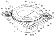
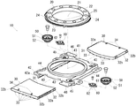
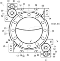
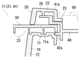
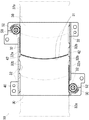
図1〜図6は、カップホルダ10の一実施例を示すものである。図1はカップホルダ10の外観を示す斜視図、図2はカップホルダ10の主要部についての分解斜視図、図3は図1の平面図、図4は図3のA−A線断面図、図5はカップホルダ10の開閉操作に伴う蓋部材30の変位態様を示す図、図6はカップホルダ10の使用状態を示す図である。
本実施例のカップホルダ10は、図1に良く示されるように、有底で上面が開口形状とされるカップ保持具70の上部に、開口を同じくしたリテイナー40(開口部41)が設けられて上面開口部11を形成している。また、図1及び図2に良く示されるように、上面開口部11には、その開口周りにリング状の操作部材20(中央の開口部21によって上面開口部11を形成している)が回動可能に配置されている。なお、本実施例においては、カップホルダ10全体としての開口部を表す概念として上面開口部11を用い、各構成要素に形成された単独の開口部を表す概念として開口部21,41を用いる。
したがって、この上面開口部11に飲物容器80を挿入する(図6参照)ことで、飲物容器80を、カップ保持具70に形成された底面の上に載置することができる。また、リテイナー40に形成された案内部42には、2部材から成る板状の蓋部材30が水平方向に挿入されており、これら蓋部材30のそれぞれが、歯車50を介して操作部材20に連結された構成となっている。したがって、このように構成されたカップホルダ10は、操作部材20を回動操作することで、蓋部材30をこれに連動させて水平方向に移動させ、上面開口部11を開閉できるようになっている。なお、これら操作部材20の回動運動を蓋部材30の水平方向移動運動に変換して伝達する歯車50等の構成(歯車50と連結状態にある操作部材20の歯部23、及び蓋部材30の歯部32a)が、本発明の変換伝達機構に相当する。
Embodiments of the best mode for carrying out the present invention will be described below with reference to the drawings.
1 to 6 show an embodiment of the
As shown well in FIG. 1, the
Therefore, the
以下、上記カップホルダ10の各部の構成について詳細に説明する。
先ず、リング状の操作部材20は、図1から図3に良く示されるように、中央に形成された開口部21と、使用時に手動操作を行う部位とされる把持部22と、把持部22の外周縁に形成された歯部23と、鍔部25と、を有して構成されている。詳しくは、歯部23は、把持部22の外周縁に沿って円弧状に2箇所形成されている。
また、歯部23が形成されたその他の外周縁部位には、鍔部25が形成されており、その端側部位には切欠き部24が形成されている。この切欠き部24は、操作部材20をリテイナー40に装着する際の嵌め入れ部位として機能する。すなわち、操作部材20の切欠き部24をリテイナー40に形成された嵌合爪44に嵌め入れて回動させると、嵌合爪44が鍔部25に嵌合して鍔部25の厚み方向への移動を規制する。なお、操作部材20は、図4に良く示されるように、内部に形成された突出部位26がリテイナー40の摺動面41aに当接状態とされており、操作部材20の回動操作を行うと、この突出部位26が摺動面41a上を摺動する。このようにして、操作部材20がリテイナー40に対して回動可能に配置されている。
Hereinafter, the structure of each part of the
First, as shown in FIGS. 1 to 3, the ring-shaped
Moreover, the
次に、歯車50は、図2及び図3に良く示されるように、リテイナー40の隅位置(2箇所)に回動可能に配置されている。具体的には、歯車50は、上側歯部51と下側歯部52とから成り、上側歯部51が前述した操作部材20に形成された歯部23にそれぞれ噛合わせ状態とされている。したがって、操作部材20を回動操作することで、これら噛合わせ状態にある2つの歯車50は、同時に回動(同一方向に)する。
また、2つの歯車50のそれぞれには、ギヤダンパー60が接続されている。詳しくは、ギヤダンパー60は、ハウジング62に対して歯部61が相対回動可能に形成されている。そして、歯部61が歯車50の上側歯部51と噛合わせ状態とされ、ハウジング62がリテイナー40に対して相対回転不可に固定されている。このギヤダンパー60によれば、ハウジング62内部に充満された流動体による粘性抵抗によって、入力された回動力を内部的に損失させる。すなわち、このギヤダンパー60と接続状態にある歯車50の回動運動に対して一定の抵抗力を付与することができる。ここで、ギヤダンパー60が本発明のダンパー手段に相当する。
Next, the
A
次に、板状に形成された2つの蓋部材30は、図2及び図5に良く示されるように、後述するリテイナー40の案内部42内に挿入されて摺動可能状態で配置されている。詳しくは、図5に良く示されるように、蓋部材30の横縁側部位32には歯部32aが形成されており、前述した歯車50の下側歯部52と噛合わせ状態とされている。更に、横縁側部位32のその他の部位には、歯部32aと突出量の等しい凸部32bが複数形成されており、これら凸部32bがリテイナー40の案内部42に当接状態となっている。更に、図4に良く示されるように、蓋部材30の下面には横縁側部位32の形成方向に凸条33が複数形成されており、後述するカップ保持具70の案内部71に形成された凹条71aに緩やかに嵌合する構成とされている。
したがって、操作部材20の回動操作を行って歯車50を回動させると、この回動力は、歯車50の下側歯部52を介して蓋部材30の歯部32aに伝達される。これにより、蓋部材30は、図5に良く示されるように、リテイナー40の案内部42に沿って水平方向移動運動を行う。換言すると、操作部材20の回動運動は、操作部材20と蓋部材30とを連結する歯車50によって、蓋部材30の水平方向移動運動に変換される。このとき、蓋部材30は、案内部42に当接状態の凸部32bによって、進行方向の横方向への移動が抑止されるため、ガタツキが抑えられて滑らかに摺動する。
Next, as shown in FIGS. 2 and 5, the two
Therefore, when the
次に、図2及び図5に良く示されるように、2つの蓋部材30の前縁側部位31は、互いに突合されて嵌合する曲面形状とされている。詳しくは、一方側の前縁側部位31が全体として凸状に張出した形状とされ、他方側の前縁側部位31が全体として凹状に窪んだ形状とされている。そして、これら蓋部材30は、前縁側部位31が向き合わされるようにして配置されている。
また、操作部材20の回動操作を行うと、蓋部材30に対して反対側に配置された2つの歯車50は同時に同一方向に回動する。したがって、歯車50に連結状態とされている2つの蓋部材30は、共に水平方向移動運動を行って相対的に接近方向または離間方向に移動する。そして、図5に良く示されるように、2つの蓋部材30が相対的に接近方向に移動して、それぞれの前縁側部位31が突合されて嵌合されると、上面開口部11は閉鎖状態となる。このとき、蓋部材30の上面に形成された係止爪34が、リテイナー40に形成された係止溝43に係合し、ストッパーとしての機能をする。
Next, as well shown in FIGS. 2 and 5, the
When the
次に、リテイナー40は、図2に良く示されるように、中央に形成された開口部41と、上述した蓋部材30を下方から支持する支持片42aを有した案内部42と、蓋部材30の係止爪34に係合する係止溝43と、を有して構成されている。また、リテイナー40の隅位置(2箇所)には歯車取付け部45とダンパー取付け部46とが形成されており、スクリュー(図示しない)によって歯車50を回動可能に軸支し、更に、ギヤダンパー60のハウジング62を相対回転不可状態に固定している。また、上面には嵌合爪44が2箇所に形成されており、操作部材20の鍔部25の厚み方向への移動を規制している。
Next, as well shown in FIG. 2, the
次に、カップ保持具70は、図1及び図4に良く示されるように、前述したリテイナー40に対して一体的に固定された状態となっている。具体的には、図4に良く示されるように、蓋部材30の凸条33に緩やかに嵌合する凹条71aが形成された案内部71と、飲物容器80を載置可能な底面を有した(有底の)保持部72と、を有して構成されている。したがって、この案内部71の凹条71aによって、蓋部材30を移動方向に案内することができる。
Next, as shown in FIGS. 1 and 4, the
続いて、本実施例のカップホルダ10の使用方法について説明する。
本実施例のカップホルダ10は、図4及び図6に良く示されるように、アッパーパネル90に対してリング状の操作部材20が露出した状態で配置されている。また、ここでは、操作部材20の回動操作によって、カップホルダ10の上面開口部11が開口状態とされているものとする。したがって、この状態のカップホルダ10に対して、飲物容器80をセットする場合には、先ず、飲物容器80を上面開口部11から挿入する。これにより、飲物容器80はカップ保持具70の底面の上に載置される。
このとき、飲物容器80の胴部の径が上面開口部11の径よりも小さい場合、すなわち、両者の間に隙間が形成される場合には、操作部材20の回動操作を行って、2つの蓋部材30を相対的に接近方向に移動(水平方向に摺動)させる。これにより、蓋部材30の前縁側部位31が飲物容器80の胴部にそれぞれ当接して、飲物容器80を側方から支持した状態となる。
次に、飲物容器80をカップ保持具70から取出した状態において、操作部材20を回動操作して、2つの蓋部材30を接近方向に移動させる。すると、図5に良く示されるように、蓋部材30のそれぞれの前縁側部位31が接近して突合されるため、上面開口部11が閉鎖状態となる。なお、操作部材20を反対方向に回動させれば、蓋部材30が相対的に離間方向に移動するため、上面開口部11が開放状態となる。このような簡単な操作(操作部材20の回動操作)によって、カップホルダ10の開閉操作が行える。
Then, the usage method of the
The
At this time, when the diameter of the body portion of the
Next, in a state where the
このように、本実施例のカップホルダ10は、リング状の操作部材20の回動操作を行うと、2つの蓋部材30を水平方向に移動させることができる。したがって、蓋部材30の前縁側部位31が突合わされる位置まで回動操作を行うという簡単な操作によって、カップホルダ10の上面開口部11を閉鎖状態とすることができる。また、上面開口部11から挿入されて載置された飲物容器80は、この開閉移動される蓋部材30によって側方から支持することができる。よって、簡単な操作によって様々な大きさの飲料容器を安定的に保持させるという機能を有しつつ、上面開口部11から入れた小物などを外部に対して隠蔽した状態にすることができる。なお、操作部材20を反対方向に回動させれば、上面開口部11を簡単に開放状態にすることができる。
更に、操作部材20の回動操作に伴って、2つの蓋部材30を同時に相対的に接近方向または離間方向に移動させることができるため、開閉操作に必要な操作部材20の回動量が少なくて済む。
更に、上述もしたように、蓋部材30は操作部材20の操作に連動するため、蓋部材30に摘み等の部位を形成する必要がない。したがって、カップホルダ10全体の見栄えが損なわれない。また、このような連動機構であるため、カップホルダ10の機能感や操作感を向上させることができる。
更に、歯車50に接続されたギヤダンパー60によって、操作部材20の回動操作に対して一定の回動抵抗を付与することができる。したがって、カップホルダ10の操作感を向上させることができ、蓋部材30の開閉操作を良好に行える。
Thus, the
Further, since the two
Further, as described above, since the
Furthermore, a certain rotational resistance can be applied to the rotational operation of the
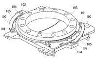
以上、本発明の実施形態を1つの実施例について説明したが、本発明は上記実施例のほか各種の形態で実施できるものである。
すなわち、本実施例においては、リング状の操作部材20の回動運動を蓋部材30の水平方向移動運動に変換して伝達する機構(本発明の変換伝達機構に相当する)を、歯車50を用いた歯車伝達の組合わせで構成されるようにしたものを示したが、例えば、図7に示すようなリンク機構100にしたものであってもよい。すなわち、一端部位101を操作部材103に回動可能に連結し、他端部位102を蓋部材104に回動可能に連結したアーム部105を設け、操作部材103の回動力によってアーム部105を揺動させて蓋部材104を押引するようにしたものであっても、本実施例と同様の作用及び効果を得ることができる。
また、本発明のダンパー手段に相当するギヤダンパー60を、歯車50に噛合わせたものを示したが、操作部材20の歯部23に噛合わせたり、蓋部材30の歯部32aに噛合わせたものであってもよい。この場合であっても、同様にして、操作部材20の回動操作に対して一定の回動抵抗を付与することができる。
更に、本実施例においては、操作部材20の回動操作によって2つの蓋部材30を連動させるものを示したが、長尺形状に形成した1つの蓋部材を連動させるようにしたものであっても良い。しかし、この場合には、本実施例で示した操作部材20の回動操作を余計に行う必要がある。
Although the embodiment of the present invention has been described with respect to one example, the present invention can be implemented in various forms in addition to the above-described example.
That is, in the present embodiment, a mechanism (corresponding to the conversion transmission mechanism of the present invention) that converts the rotational movement of the ring-shaped
Further, although the
Further, in this embodiment, the two
10 カップホルダ
11 上面開口部
20 操作部材
21 開口部
22 把持部
23 歯部(変換伝達機構)
24 切欠き部
25 鍔部
26 突出部位
30 蓋部材
31 前縁側部位
32 横縁側部位
32a 歯部(変換伝達機構)
32b 凸部
33 凸条
34 係止爪
40 リテイナー
41 開口部
41a 摺動面
42 案内部
42a 支持片
43 係止溝
44 嵌合爪
45 歯車取付け部
46 ダンパー取付け部
50 歯車(変換伝達機構)
51 上側歯部
52 下側歯部
60 ギヤダンパー(ダンパー手段)
61 歯部
62 ハウジング
70 カップ保持具
71 案内部
71a 凹条
72 保持部
80 飲物容器
90 アッパーパネル
100 リンク機構
101 一端部位
102 他端部位
103 操作部材
104 蓋部材
105 アーム部
DESCRIPTION OF
24
51
61
Claims (4)
前記上面開口部を開閉する蓋部材は板状に形成されており、前記箱形状を形成する構成部材に水平方向に移動可能に設置されており、かつ、
前記上面開口部にはその開口周りにリング状の操作部材が回動可能に配置されており、該操作部材の回動運動を前記蓋部材の水平方向移動運動に変換して伝達する変換伝達機構により操作部材と蓋部材とが連結され、該操作部材の回動操作により蓋部材が上面開口部を開閉することを特徴とするカップホルダ。 The cup holder is formed in a box shape having a bottom and an upper surface opened so that a beverage container can be placed, and an upper surface opening portion into which the beverage container is inserted can be opened and closed by a lid member,
The lid member that opens and closes the upper surface opening is formed in a plate shape, is installed on the component member that forms the box shape so as to be movable in the horizontal direction, and
A ring-like operation member is rotatably disposed around the upper surface opening, and a conversion transmission mechanism that converts the rotation movement of the operation member into a horizontal movement movement of the lid member and transmits it. The cup holder is characterized in that the operating member and the lid member are connected by the lid, and the lid member opens and closes the upper surface opening by rotating the operating member.
前記変換伝達機構は歯車伝達の組合わせで構成されていることを特徴とするカップホルダ。 The cup holder according to claim 1,
A cup holder, wherein the conversion transmission mechanism is configured by a combination of gear transmission.
前記蓋部材は2つの部材から成り、前記リング状の操作部材の回動操作を行うと該2つの蓋部材が共に相対的に接近方向または離間方向に水平方向移動運動を行うように構成され、該2つの蓋部材が突合わされて前記上面開口部が閉鎖されることを特徴とするカップホルダ。 The cup holder according to claim 1 or 2,
The lid member is composed of two members, and is configured such that when the ring-shaped operation member is rotated, the two lid members perform a horizontal movement in a relatively approaching direction or a separating direction. A cup holder, wherein the two lid members are abutted to close the upper surface opening.
前記変換伝達機構は、流動体を用いたダンパー手段が設けられていることを特徴とするカップホルダ。
The cup holder according to any one of claims 1 to 3,
The said conversion transmission mechanism is provided with the damper means using the fluid, The cup holder characterized by the above-mentioned.
Priority Applications (1)
| Application Number | Priority Date | Filing Date | Title |
|---|---|---|---|
| JP2004118099A JP4519506B2 (en) | 2004-04-13 | 2004-04-13 | Cup holder |
Applications Claiming Priority (1)
| Application Number | Priority Date | Filing Date | Title |
|---|---|---|---|
| JP2004118099A JP4519506B2 (en) | 2004-04-13 | 2004-04-13 | Cup holder |
Publications (2)
| Publication Number | Publication Date |
|---|---|
| JP2005297812A true JP2005297812A (en) | 2005-10-27 |
| JP4519506B2 JP4519506B2 (en) | 2010-08-04 |
Family
ID=35329877
Family Applications (1)
| Application Number | Title | Priority Date | Filing Date |
|---|---|---|---|
| JP2004118099A Expired - Fee Related JP4519506B2 (en) | 2004-04-13 | 2004-04-13 | Cup holder |
Country Status (1)
| Country | Link |
|---|---|
| JP (1) | JP4519506B2 (en) |
Cited By (1)
| Publication number | Priority date | Publication date | Assignee | Title |
|---|---|---|---|---|
| JP2013525207A (en) * | 2010-05-05 | 2013-06-20 | マッカスリン イノベーションズ, リミテッド ライアビリティ カンパニー | A device for substantially minimizing accidental tipping of partially filled containers |
Citations (4)
| Publication number | Priority date | Publication date | Assignee | Title |
|---|---|---|---|---|
| JPS62139747U (en) * | 1986-02-28 | 1987-09-03 | ||
| JPH02143231U (en) * | 1989-05-01 | 1990-12-05 | ||
| JPH04128941U (en) * | 1991-03-27 | 1992-11-25 | 日本プラスト株式会社 | Console box with armrest |
| JPH10226260A (en) * | 1997-02-12 | 1998-08-25 | Fuji Heavy Ind Ltd | On-vehicle console box cup holder |
-
2004
- 2004-04-13 JP JP2004118099A patent/JP4519506B2/en not_active Expired - Fee Related
Patent Citations (4)
| Publication number | Priority date | Publication date | Assignee | Title |
|---|---|---|---|---|
| JPS62139747U (en) * | 1986-02-28 | 1987-09-03 | ||
| JPH02143231U (en) * | 1989-05-01 | 1990-12-05 | ||
| JPH04128941U (en) * | 1991-03-27 | 1992-11-25 | 日本プラスト株式会社 | Console box with armrest |
| JPH10226260A (en) * | 1997-02-12 | 1998-08-25 | Fuji Heavy Ind Ltd | On-vehicle console box cup holder |
Cited By (1)
| Publication number | Priority date | Publication date | Assignee | Title |
|---|---|---|---|---|
| JP2013525207A (en) * | 2010-05-05 | 2013-06-20 | マッカスリン イノベーションズ, リミテッド ライアビリティ カンパニー | A device for substantially minimizing accidental tipping of partially filled containers |
Also Published As
| Publication number | Publication date |
|---|---|
| JP4519506B2 (en) | 2010-08-04 |
Similar Documents
| Publication | Publication Date | Title |
|---|---|---|
| JP4294623B2 (en) | Vehicle storage device | |
| US7757888B2 (en) | Telescoping cup holder for automotive consoles | |
| US8939491B2 (en) | Multiple container holder assembly | |
| US20100102063A1 (en) | Lid body opening and closing device | |
| JP2004203067A (en) | Glove compartment | |
| CA2658623C (en) | Baggage bin and associated door intended in particular for an aircraft | |
| CN107054188B (en) | Automobile seat with folding small table plate | |
| WO2012173246A1 (en) | Lid opening and closing mechanism and storage device | |
| JP4218225B2 (en) | Opening / closing device for storage unit lid | |
| JP4519506B2 (en) | Cup holder | |
| JP5644720B2 (en) | Console Box | |
| JP2008105473A (en) | Vehicular floor console structure | |
| JP2007196884A (en) | Bottle holder | |
| JP6576840B2 (en) | Cup holder | |
| JP4437950B2 (en) | Vehicle console box | |
| KR100668895B1 (en) | Tray for the vehicle | |
| JP3625740B2 (en) | Vehicle storage | |
| JPH10166952A (en) | Console box | |
| CN211001146U (en) | Novel multi-functional convertible storing box | |
| KR101126903B1 (en) | In-vehicle housing | |
| JP2538549Y2 (en) | Console Box | |
| KR200193978Y1 (en) | Arm rest with cup holder in console box | |
| JPH0640018Y2 (en) | Car grab box equipment | |
| JP2016007865A (en) | Biparting storage device | |
| JPH0621785Y2 (en) | Center console box for passenger cars |
Legal Events
| Date | Code | Title | Description |
|---|---|---|---|
| A621 | Written request for application examination |
Free format text: JAPANESE INTERMEDIATE CODE: A621 Effective date: 20061016 |
|
| A977 | Report on retrieval |
Free format text: JAPANESE INTERMEDIATE CODE: A971007 Effective date: 20090324 |
|
| A131 | Notification of reasons for refusal |
Free format text: JAPANESE INTERMEDIATE CODE: A131 Effective date: 20091110 |
|
| A521 | Written amendment |
Free format text: JAPANESE INTERMEDIATE CODE: A523 Effective date: 20100104 |
|
| TRDD | Decision of grant or rejection written | ||
| A01 | Written decision to grant a patent or to grant a registration (utility model) |
Free format text: JAPANESE INTERMEDIATE CODE: A01 Effective date: 20100518 |
|
| A01 | Written decision to grant a patent or to grant a registration (utility model) |
Free format text: JAPANESE INTERMEDIATE CODE: A01 |
|
| A61 | First payment of annual fees (during grant procedure) |
Free format text: JAPANESE INTERMEDIATE CODE: A61 Effective date: 20100519 |
|
| FPAY | Renewal fee payment (event date is renewal date of database) |
Free format text: PAYMENT UNTIL: 20130528 Year of fee payment: 3 |
|
| R150 | Certificate of patent or registration of utility model |
Free format text: JAPANESE INTERMEDIATE CODE: R150 |
|
| FPAY | Renewal fee payment (event date is renewal date of database) |
Free format text: PAYMENT UNTIL: 20140528 Year of fee payment: 4 |
|
| R250 | Receipt of annual fees |
Free format text: JAPANESE INTERMEDIATE CODE: R250 |
|
| R250 | Receipt of annual fees |
Free format text: JAPANESE INTERMEDIATE CODE: R250 |
|
| R250 | Receipt of annual fees |
Free format text: JAPANESE INTERMEDIATE CODE: R250 |
|
| LAPS | Cancellation because of no payment of annual fees |