JP2005297778A - Air conditioner for vehicle - Google Patents
Air conditioner for vehicle Download PDFInfo
- Publication number
- JP2005297778A JP2005297778A JP2004117054A JP2004117054A JP2005297778A JP 2005297778 A JP2005297778 A JP 2005297778A JP 2004117054 A JP2004117054 A JP 2004117054A JP 2004117054 A JP2004117054 A JP 2004117054A JP 2005297778 A JP2005297778 A JP 2005297778A
- Authority
- JP
- Japan
- Prior art keywords
- air
- vehicle
- heat exchanger
- conditioning unit
- outlet
- Prior art date
- Legal status (The legal status is an assumption and is not a legal conclusion. Google has not performed a legal analysis and makes no representation as to the accuracy of the status listed.)
- Pending
Links
- 238000004378 air conditioning Methods 0.000 claims abstract description 57
- 238000001816 cooling Methods 0.000 claims description 21
- 238000010438 heat treatment Methods 0.000 claims description 17
- 238000007664 blowing Methods 0.000 claims description 12
- 230000001143 conditioned effect Effects 0.000 claims description 11
- 238000009423 ventilation Methods 0.000 abstract description 7
- 230000004048 modification Effects 0.000 description 6
- 238000012986 modification Methods 0.000 description 6
- 230000000694 effects Effects 0.000 description 4
- 230000004308 accommodation Effects 0.000 description 2
- 238000004904 shortening Methods 0.000 description 1
Images
Landscapes
- Instrument Panels (AREA)
- Air-Conditioning For Vehicles (AREA)
Abstract
Description
本発明は、インストルメンタルパネルの裏側に配置される車両用空調装置に関する。 The present invention relates to a vehicle air conditioner disposed on the back side of an instrumental panel.
車両内の空調を行う車両用空調装置(空調ユニット)は、一般的に車両内における車室前方側のインストルメントパネルの裏側に配置されている。 BACKGROUND ART A vehicle air conditioner (air conditioning unit) that performs air conditioning in a vehicle is generally disposed on the back side of an instrument panel on the front side of a passenger compartment in the vehicle.
一方、自動車においては、車体の横方向の剛性の確保やステアリング保持用として、梁状の支柱部材(以下、クロスカービームとする)が車室を車幅方向に沿って横切るようにインストルメントパネルの裏側に配置される。このようなことから、車両用空調ユニットとクロスカービームとの干渉が問題となる。 On the other hand, in the case of automobiles, an instrument panel is used so that a beam-shaped support member (hereinafter referred to as a cross car beam) crosses the passenger compartment along the vehicle width direction in order to ensure the rigidity of the vehicle body in the lateral direction and to maintain the steering. It is arranged on the back side. For this reason, the interference between the vehicle air conditioning unit and the cross car beam becomes a problem.
この点、特許文献1に開示された車両用空調装置では、クロスカービームと車両用空調装置との干渉を避けるために、クロスカービームを空調ユニットを逃げるように屈曲させてその上方に配置している。
In this regard, in the vehicle air conditioner disclosed in
また、特許文献2に開示された車両空調装置では、クロスカービームを空調ユニット内に貫通させ、このクロスカービームにより空調ユニットを支持させている。
特許文献1に開示された車両用空気調和装置では、クロスカービームを曲げて空調ユニットに対する干渉を避けて個別に配置しているため、インストルメンタルパネルの裏側のスペースをクロスカービームおよびインストルメンタルパネルとで取り合うことになり、スペースを有効利用することが困難となる可能性があった。
In the vehicle air conditioner disclosed in
また、特許文献2に開示された車両用空調装置では、ユニット内の通風路がクロスカービームにより塞がれて通気抵抗を増大させる可能性が生じていた。
Moreover, in the vehicle air conditioner disclosed in
本発明は、このような従来の問題点を考慮してなされたものであり、クロスカービームを車両用空調装置内に貫通させながら、通気抵抗の増大を回避することを可能にした車両用空調装置を提供することをその目的とする。 The present invention has been made in consideration of such conventional problems, and it is possible to avoid the increase in ventilation resistance while allowing the cross car beam to penetrate the vehicle air conditioner. The object is to provide a device.
請求項1記載の発明は、車両のインストルメンタルパネルの裏側に車室を横断するように配置されるクロスカービームに組みつけられる車両用空調装置であって、上方壁部に空気吹出口が形成された収容ケース、および該収容ケースに収容された冷却用および加熱用熱交換器を含み、ブロワから送出された空気を前記冷却用熱交換器により冷却し、かつ前記加熱用熱交換器により加熱し、該冷却により得られた冷風および該加熱により得られた温風を前記空気吹出口から吹出す第1の空調ユニットと、エアミックスチャンバが内部に形成され、かつ複数の空調風吹出口が形成されたエアミックス用ケースを含み、前記空気吹出口から吹出した冷風および温風を該エアミックスチャンバ内で混合して空調風を生成する第2の空調ユニットとを備えつつ、前記クロスカービームの途中に空気流通可能な送風孔を設け、前記第1の空調ユニットと前記第2の空調ユニットによって、前記クロスカービームを狭持し、前記空気吹出口が前記送風孔を介して連通するように車高方向に沿って対向配置したことを特徴とする。
The invention according to
請求項2記載の発明は、前記冷却用熱交換器を、その空気流入面および空気流出面が車高方向に対して所定角度を成すように傾斜配置し、前記加熱用熱交換器を、その空気流入面が下側および空気流出面が上側になるように傾斜配置したことを特徴とする。 According to a second aspect of the present invention, the cooling heat exchanger is inclined so that the air inflow surface and the air outflow surface form a predetermined angle with respect to the vehicle height direction, and the heating heat exchanger is It is characterized by being inclined so that the air inflow surface is on the lower side and the air outflow surface is on the upper side.
請求項3記載の発明は、前記冷却用熱交換器を、その空気流入面が下側および空気流出面が上側になるように傾斜配置したことを特徴とする。
The invention according to
請求項4記載の発明は、上方視した際に、前記冷却用熱交換器の後端部に前記加熱用熱交換器の前端部が重なるように該冷却用熱交換器と該加熱用熱交換器を平行に配置したことを特徴とする。 According to a fourth aspect of the present invention, when viewed from above, the cooling heat exchanger and the heating heat exchange are arranged so that the rear end portion of the cooling heat exchanger overlaps the front end portion of the heating heat exchanger. It is characterized by arranging the vessels in parallel.
請求項5記載の発明は、前記エアミックスチャンバに連通されたデフロスタ吹出口と、このデフロスタ吹出口に連通し、かつ前記車軸方向に沿って車両前方側に延出するデフロスタ吹出通路とをさらに備えたことを特徴とする。
The invention according to
請求項1記載の発明によれば、第1の空調ユニットの冷却用熱交換器および加熱用熱交換器により温度調整された冷風および温風は、通気抵抗を受けることなく、クロスカービームに形成された送風孔60および61を介して第2の空調ユニットのエアミックスチャンバにそれぞれ流入して空調風が生成され、空調風吹出口を介して所望の方向へ吹出されて空調が行われる。
According to the first aspect of the present invention, the cold air and the hot air whose temperature is adjusted by the cooling heat exchanger and the heating heat exchanger of the first air conditioning unit are formed in the cross car beam without receiving a ventilation resistance. The conditioned air is generated by flowing into the air mix chamber of the second air conditioning unit through the
すなわち、本実施形態によれば、クロスカービームを車両用空調装置内に貫通する構成を、空調用空気(冷風および温風)に対する通気抵抗を増大させることなく実現することができる。 That is, according to the present embodiment, the configuration in which the cross car beam penetrates into the vehicle air conditioner can be realized without increasing the airflow resistance with respect to the air for air conditioning (cold air and hot air).
このため、インストルメンタルパネルの裏側においてクロスカービームを車両用空調装置を避けて配置する必要がなくなり、インストルメンタルパネルの裏側のスペースを有効活用することができる。 For this reason, it is not necessary to arrange the cross car beam avoiding the vehicle air conditioner on the back side of the instrument panel, and the space on the back side of the instrument panel can be effectively utilized.
また、請求項2記載の発明によれば、冷却用熱交換器を、空気流入面および空気流出面が車高方向に対して所定角度を成すように傾斜配置し、加熱用熱交換器を、その空気流入面が下側および空気流出面が上側になるように傾斜配置しているため、冷却用交換器および加熱用熱交換器をそれぞれの空気流入面および流出面を車高方向に沿って縦配置した場合に比べて、車両用空調装置の車高方向の寸法を短縮することができる。
According to the invention described in
特に、請求項3記載の発明によれば、冷却用熱交換器における空気の流出方向を上方に設定することができるため、冷却用熱交換器から流出された空気の送風抵抗を低減することが可能になり、空調をスムーズに行うことができる。
In particular, according to the invention described in
また、特に、請求項4記載の発明によれば、空調装置を上方視した際に、冷却用熱交換器の後端部に加熱用熱交換器の前端部が重なるように平行に配置したことで、車軸方向の寸法を短縮し、装置全体を小型化することができる。 Further, in particular, according to the invention described in claim 4, when the air conditioner is viewed from above, it is arranged in parallel so that the front end of the heating heat exchanger overlaps the rear end of the cooling heat exchanger. Thus, the dimension in the axle direction can be shortened and the entire apparatus can be downsized.
さらに、請求項5記載の発明によれば、デフロスタ吹出通路を車両前方側へ車軸方向に沿って延出させたため、このデフロスタ吹出通路を介してデフロスタ用空気を車両前方方向に向かって吹出させることができ、従来の車高方向上方側に向かって吹出させる構成と比べて、さらに車高方向の寸法を短縮することができ、上記車室内の居住性向上およびリビングルーム化にさらに寄与することができる。 According to the fifth aspect of the present invention, since the defroster outlet passage is extended along the axle direction toward the vehicle front side, the defroster air is blown out toward the vehicle front direction through the defroster outlet passage. Compared with the conventional structure that blows out toward the upper side in the vehicle height direction, the size in the vehicle height direction can be further shortened, which can further contribute to the improvement of the comfort in the vehicle interior and the living room. it can.
以下、本発明を図示する一実施形態により、具体的に説明する。なお、実施形態において、同一の部材には同一の符号を付して対応させてある。 Hereinafter, the present invention will be specifically described with reference to an embodiment illustrated in the drawings. In the embodiment, the same members are assigned the same reference numerals.
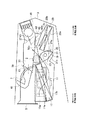
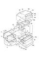
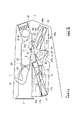
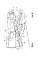
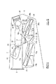
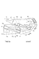
図1は、本発明の一実施形態に係わる車両用空調装置の概略縦断面図、図2は、図1に示す車両用空調装置の概略分解斜視図である。なお、図2においては、図1に示されたユニットケース、デフロスタ通路、およびベント通路の図示を省略している。 FIG. 1 is a schematic longitudinal sectional view of a vehicle air conditioner according to an embodiment of the present invention, and FIG. 2 is a schematic exploded perspective view of the vehicle air conditioner shown in FIG. In FIG. 2, the unit case, the defroster passage, and the vent passage shown in FIG. 1 are not shown.
図1および図2に示すように、車両用空調装置1は、例えば車両のインストルメンタルパネルの裏側に配置され、そのインストルメンタルパネル裏側において車幅方向に延びて車体に固定されたクロスカービーム2に組みつけられている。
As shown in FIGS. 1 and 2, a
すなわち、車両用空調装置1は、ユニットケース3と、このユニットケース3に取り付けられ、車両前方側外方に開口する外気導入口5と、ユニットケース3に取り付けられ、車室内側に開口し、外気導入口5に対して所定間隔を空けて対向する内気導入口7とを備えている。
That is, the
また、車両用空調装置1は、外気導入口5および内気導入口7に対して連通され、この外気導入口5および内気導入口7を介して導入された外気および内気をブロワファン9を介して吸い込むブロワ11と、外気導入口5および内気導入口7間に揺動自在に設けられ、外気導入口5および内気導入口7の開閉を切替る内外切替ドア13とを備えている。すなわち、この内外切替ドア13は、外気導入口側に揺動して外気導入口5を閉鎖して内気導入口7を開放し、内気導入口7側へ揺動して内気導入口7を閉鎖して外気導入口5を開放可能になっている。
The
車両用空調装置1は、このブロワ11に対して車幅方向に沿って並置され、かつブロワ11の空気流出路11aに空気取入口15aを介して内部が連通しており、後述する熱交換器を収容する収容ケース15を有し、車両用空調装置1における熱交換ユニットを構成する第1の空調ユニット16とを備えている。
The
第1の空調ユニット16は、収容ケース15の車両前方側端部内に設置された冷却用熱交換器であるエバポレータ17を備えている。
The first
エバポレータ17は、ブロワ11に対して車幅方向に沿って、その空気流入面17aが空気取入口15aに対向するように配置されている。
The
また、第1の空調ユニット16は、収容ケース15内におけるエバポレータ17に対して下流側(車両後方側)に配置されたエアミックスドア19を備えている。
The first
このエアミックスドア19は、縦断面略扇形の中空円筒形状を有し、その円弧状側面21aに対向する側面21bが開口するドアケース21を備え、このドアケース21は、その軸方向が車幅方向に沿い、かつ開口側面21bがエバポレータ下流側に面するように配設されている。
The
また、エアミックスドア19は、その円弧状側面21aの上方側に形成されたバイパス通路23と、円弧状側面21aの車両後方側に形成されたヒータコア側通路25と、円弧状側面21aの略半分の円弧形状を有し、円弧状側面21aに対してその円弧面に沿ってスライド自在に支持されており、このスライド動作によりバイパス通路23およびヒータコア側通路25の開閉を切替る円弧状ドア27とを備えている。
The
すなわち、この円弧状ドア27は、ミックスチャンバ側通路側にスライドしてバイパス通路23を閉鎖してヒータコア側通路25を開放し、ヒータコア側通路側へスライドしてヒータコア側通路25を閉鎖してバイパス通路23を開放可能になっている。
That is, the arc-
このとき、エバポレータ17は、その空気流入面17aおよび冷却後の空気流出面17bが車高方向に対して所定角度を成すように、例えば空気流出面17bがエアミックスドア19における空気流入側の開口側面21bに臨むように傾斜配置されている。
At this time, the
さらに、第1の空調ユニット16は、収容ケース15における車両後方側端部内におけるエアミックスドア19のヒータコア側通路25の下流側(車両後方側)に配置された加熱用熱交換器であるヒータコア29を備えており、エアミックスドア19は、エバポレータ17およびヒータコア29間に介在した構成となっている。
Further, the first
ヒータコア29は、その空気流入面29aおよび温度調節後の空気流出面29bが車高方向に対して所定角度を成すように、例えばその空気流入面29aがエアミックスドア19におけるヒータコア側通路25に臨むように傾斜配置されている。
For example, the
ヒータコア29の空気流出面29b上方および収容ケース15の車両後方側壁部との間には、ヒータコア29により温度調節された空気(温風)が流れる温風通路31が空気流出面29bに沿って形成されている。
A
そして、本実施形態において、収容ケース15におけるエアミックスドア19の上方の壁部が下側に凹んで上記クロスカービーム取り付け用の取り付け凹溝Gが形成されており、この取り付け凹溝Gの底部には、バイパス通路23および温風通路31にそれぞれ連通する空気吹出口15bが形成されている。
And in this embodiment, the upper wall part of the
一方、車両用空調装置1は、第1の空調ユニット16における収容ケース15の上方を覆う中空状かつ底面が開口するエアミックス用ケース30aを含む第2の空調ユニット30を備えている。
On the other hand, the
この第2の空調ユニット30におけるエアミックス用ケース30aの内部スペース33は、温風通路31から空気吹出口15bを介して吹出された温風とバイパス通路23から空気吹出口15bを介して吹出された冷風との合流・混合部分であるエアミックスチャンバ33として構成されている。
The
第2の空調ユニット30におけるエアミックス用ケース30aの車両後方側壁部には、ユニットケース3に設けられたセンタベント吹出用のセンタベント吹出通路35および図示せぬサイドベント吹出通路にそれぞれ連通するベント吹出口37が形成されており、このベント吹出口37は、エアミックスチャンバ33に連通されている。
A vent that communicates with a center
また、第2の空調ユニット30におけるエアミックス用ケース30aの車両前方側壁部には、エアミックスチャンバ33に連通されたデフロスタ吹出口39が形成されている。
Further, a
そして、第2の空調ユニット30におけるエアミックス用ケース30aの車両前方側壁部の外側には、デフロスタ吹出口39に連通し、かつ車両前方側へ車軸方向に沿って延び、その開口側先端が上方に屈曲したデフロスタ吹出用のデフロスタ吹出通路41が取り付けられている。
In addition, the outside of the vehicle front side wall portion of the
一方、収容ケース15の車両後方側一端部およびエアミックス用ケース30aの車両後方側一端部間には、エアミックス用ケース30aのエアミックスチャンバ33に連通するフット吹出通路42を区画形成する吹出スペース43が取り付けられており、この吹出スペース43の車幅方向側の両側壁部には、フット吹出通路42に連通するフット吹出口43aがそれぞれ形成されている。
On the other hand, between the one end part on the vehicle rear side of the
さらに、ベント吹出口37には、そのベント吹出口37を開閉可能なバタフライ式のベントドア45が取り付けられ、デフロスタ吹出口39には、そのデフロスタ吹出口39を開閉可能なバタフライ式のデフロスタドア47が取り付けられている。
Further, a
また、吹出スペース43には、その吹出スペース43を開閉可能な片持ち回動式のフットドア49が取り付けられている。
Further, a cantilevered pivot
そして、上述したように、本実施形態においては、クロスカービーム2は、第1の空調ユニット16および第2の空調ユニット30間に形成されたクロスカービーム取り付け凹溝G内を貫通するように配設されている。
As described above, in the present embodiment, the
クロスカービーム2は、長さ方向の略中央部分に位置し、第1の空調ユニット16および第2の空調ユニット30間に介挿された送風用ブロック52と、この送風用ブロック52の長さ方向の両端部から車幅方向に沿って延びる一対のサイドビーム53、54とによって構成されている。サイドビーム53、54は、他の部材となるものであり、パイプ材が使用されることによりクロスカービーム2に所定の剛性を付与するようになっている。
The
送風用ブロック52は、平面から見て略矩形状に形成されており、長さ方向の両端部には、サイドビーム53、54が連結されるサイドブラケット52a、52bが形成されている。これらのサイドブラケット52a、52bとの間には、略矩形状のメインブロック52cが一体的に形成されている。
The
メインブロック52cは、第1の空調ユニット16および第2の空調ユニット30間の取り付け凹溝Gに嵌合し、このメインブロック52cには、エアミックスチャンバ33および空気吹出口15bに連通する2つの送風孔60、61が車高方向に貫通するようにそれぞれ独立して区画形成されている。
The
次に、本実施形態における車両用空調装置1の動作について、特に各空調モード(デフロスタモード、ベントモード、フットモード、およびバイレベルモード)時の動作および空気(空調風)の流れについて説明する。
Next, the operation of the
外気導入口5および内気導入口7の内の少なくとも一方から導入された空気は、ブロワファン9によりブロワ11内に吸い込まれる。
Air introduced from at least one of the
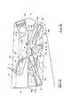
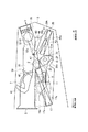
ブロワ11に吸い込まれた空気は、ブロワ11の空気流出路11aを介して車幅方向に流れ、空気流入面17aを介して第1の空調ユニット16におけるエバポレータ17に流入する(図3〜図6中符号A参照)。
The air sucked into the
エバポレータ17に流入された空気は、エバポレータ17の熱交換機能により冷却され、この冷風は、空気流出面17bを介してエアミックスドア19に流入する。
The air that has flowed into the
エアミックスドア19に流入された冷風は、エアミックスドア19の円弧状ドア27のスライド動作により分流され、一方は、バイパス通路23を介して上方に進み(符号A1参照)、他方は、ヒータコア側通路25および空気流入面29aを介してヒータコア29に流入する。
The cold air that has flowed into the
ヒータコア29に流入された冷風は、ヒータコア29の熱交換機能により加熱され、この温風は、温風通路31を介して上方に進む(符合A2参照)。
The cool air that has flowed into the
バイパス通路23を通って上方に進んだ冷風(符号A1)および温風通路31を介して上方に進む温風(符号A2)は、それぞれ空気吹出口15bを介して収容ケース15から流出する。
The cool air (reference A1) that has traveled upward through the
このとき、本実施形態では、この空気吹出口15bに対し、クロスカービーム2のメインブロック52cに形成された送風孔60および61がそれぞれ連通されているため、冷風A1および温風A2は、この送風孔60および61の内の何れか一方を通って上方に進み、第2の空調ユニット30におけるエアミックスチャンバ33に流入し、このエアミックスチャンバ33内でミックス(混合)される。
At this time, in the present embodiment, since the air blow holes 60 and 61 formed in the
以下の動作は空調モードによって分かれる。 The following operations are divided according to the air conditioning mode.
(a)デフロスタモード
車両用空調装置1が(a)デフロスタモードである場合、図示しない制御手段により、図3に示すように、デフロスタドア47が開、ベントドア45が閉、フットドア49が閉と制御され、デフロスタ吹出口39およびデフロスタ吹出通路41を介して上記ミックスされた空調風(あるいはフルホットの温風)が吹出される(図3中符号D参照)。
(A) Defroster Mode When the
(b)ベントモード
車両用空調装置1が(b)ベントモードである場合、図示しない制御手段により、図4に示すように、ベントドア45が開、デフロスタドア47が閉、フットドア49が閉と制御され、ベント吹出口37およびセンタベント吹出通路35およびサイドベント通路を介して上記ミックスされた空調風(あるいはフルクールの冷風)が吹出される(図4中符号V参照)。
(B) Vent Mode When the
(c)フットモード
車両用空調装置1が(c)フットモードである場合、図示しない制御手段により、図5に示すように、フットドア49が開、ベントドア45が閉、デフロスタドア47が閉と制御され、フット吹出通路42およびフット吹出口43aを介して上記ミックスされた空調風(あるいはフルホットの温風)が吹出される(図5中符号F参照)。
(C) Foot mode When the
(d)バイレベルモード
車両用空調装置1が(d)バイレベルモードである場合、図示しない制御手段により、図6に示すように、ベントドア45が半開、フットドア49が半開、デフロスタドア47が閉と制御される。この結果、ベント吹出口37およびセンタベント吹出通路35およびサイドベント通路を介して上記ミックスされた空調風Vが吹出され、また、フット吹出通路42およびフット吹出口43aを介して上記ミックスされた空調風Fが吹出される(図6中符号VおよびF参照)。
(D) Bi-level mode When the
次に、本実施形態における車両用空調装置1の作用効果について説明する。
Next, the effect of the
本構成によれば、車両用空調装置1を、熱交換機能を司る第1の空調ユニット16と、この第1の空調ユニット16の熱交換機能により温調された冷風および温風の混合機能および吹出し制御機能を司る第2の空調ユニット30とに分離して構成し、この第1の空調ユニット16および第2の空調ユニット30をクロスカービーム2を挟んで対向配置し、このクロスカービーム2における上記冷風および温風の第2の空調ユニット30側への流路部分に送風孔60および61をそれぞれ形成することにより、エアミックスチャンバ33および空気吹出口15bを送風孔60、61を介して連通させている。
According to this configuration, the
このため、上記第1の空調ユニット16により温度調整された冷風および温風は、通気抵抗を受けることなく、その送風孔60および61を介して第2の空調ユニット30のエアミックスチャンバ33に流入し、各ドア45、47、49の開閉切替制御により、所望の方向へ吹出されて空調が行われる。
For this reason, the cold air and the hot air whose temperature is adjusted by the first
すなわち、本実施形態によれば、クロスカービーム2を車両用空調装置1内に貫通する構成を、空調用空気に対する通気抵抗を増大させることなく実現することができる。
That is, according to the present embodiment, the configuration in which the
このため、インストルメンタルパネルの裏側においてクロスカービーム2を車両用空調装置1を避けて配置する必要がなくなり、インストルメンタルパネルの裏側のスペースを有効活用することができる。したがって、例えば車高方向に沿って薄厚のテーブルタイプのインストルメンタルパネルを利用することが可能になり、車室内の居住性向上およびリビングルーム化に寄与することができる。
For this reason, it is not necessary to arrange the
また、本実施形態によれば、車両用空調装置1をクロスカービーム2により車体に対して固定支持することができるため、薄厚化されたインストルメンタルパネルの強度も十分維持することができる。
Moreover, according to this embodiment, since the
さらに、本実施形態では、エバポレータ17を、その空気流入面17aおよび冷却後の空気流出面17bが車高方向に対して所定角度を成すように傾斜配置し、かつヒータコア29を、その空気流入面29aおよび温度調節後の空気流出面29bが車高方向に対して所定角度を成すように傾斜配置している。
Further, in the present embodiment, the
このため、エバポレータ17およびヒータコア29を、それぞれの空気流入面および流出面を車高方向に沿って縦配置した場合に比べて、車両用空調装置1の車高方向の長さ(寸法)を短縮することができる。
For this reason, the length (dimensions) of the
この結果、インストルメンタルパネルの車高方向における薄厚テーブル化がさらに容易となり、車室内の居住性向上およびリビングルーム化にさらに寄与することができる。 As a result, it becomes easier to make the instrumental panel thinner in the vehicle height direction, which can further contribute to improving the comfort of the passenger compartment and the living room.
また、本実施形態においては、エバポレータ17をブロワ11に対して車幅方向に設置しているため、ブロワ11を介して取り込んだ空気の流路の方向を車幅方向に設定することができる。
In the present embodiment, since the
したがって、従来のブロワおよびエバポレータを車高方向に並置した構造と比べて車高方向の長さ(寸法)をさらに短縮することができ、上記車室内の居住性向上およびリビングルーム化にさらに寄与することができる。 Therefore, the length (dimension) in the vehicle height direction can be further reduced as compared with the conventional structure in which the blower and the evaporator are juxtaposed in the vehicle height direction, which further contributes to the improvement of the comfort in the vehicle interior and the living room. be able to.
特に、本実施形態では、エバポレータ17を、その空気流出面17bがエアミックスドア19の空気流入部位である開口側面21bに臨むように傾斜配置し、さらにヒータコア29を、その空気流入面29aがエアミックスドア19のヒータコア側への空気流出部位であるヒータコア側通路25に臨むように傾斜配置しているため、エバポレータ17、エアミックスドア19、およびヒータコア29間の空気の流通を良好に維持しながら、上記車高方向の寸法短縮効果を得ることができる。
In particular, in the present embodiment, the
また、本実施形態においては、デフロスタ吹出通路41を車両前方側へ車軸方向に沿って延設したため、デフロスタ風Dを車両前方方向に向かって吹出させることができ、従来の車高方向上方側に向かってデフロスタ風を吹出させる構成と比べて、さらに車高方向の寸法を短縮することができ、上記車室内の居住性向上およびリビングルーム化にさらに寄与することができる。
Further, in the present embodiment, since the
なお、本実施形態においては、フット吹出通路42およびフット吹出口43aを収容ケース15およびエアミックス用ケース30aの後方側一端部に設けたが、本発明はこの構成に限定されるものではなく、エアミックス用ケース30aの車幅方向側の両側壁部にフット吹出口43aを設け、そのフット吹出口43aにフットドア49をそれぞれ取り付けてもよい。
In the present embodiment, the
また、上記実施形態およびその変形例においては、エアミックスドア装置を円弧状ドアスライド式の装置としたが、本発明はこの構成に限定されるものではなく、片持ち回動式の板状ドア装置としてもよい。 Moreover, in the said embodiment and its modification, although the air mix door apparatus was made into the circular-arc-shaped door slide-type apparatus, this invention is not limited to this structure, The plate-shaped door of a cantilever rotation type It is good also as an apparatus.
さらに、本実施形態およびその変形例においては、エバポレータをその空気流出面17bがエアミックスドア19(板状ドア装置)の空気流入部位に臨むように傾斜配置したが、本発明はこの構成に限定されるものではなく、図7(図1に対応)に示すように、エバポレータ77を、その空気流入面77aが空気流入部位(エアミックスドア19の開口側面21b、あるいはドア装置のドア部開閉領域)に臨むように傾斜配置してもよい。
Further, in the present embodiment and its modifications, the evaporator is inclined so that the
この構成では、ブロワ11の空気流出路11aに連通する空気取入口15aは、収容ケース15の車両前方側端部の底部に設けられており、エバポレータ77は、その空気流入面77aが下側および空気流出面77bが上側になり、かつ空気流出面77bが分流部19の開口側面21bに臨むように傾斜配置されている。
In this configuration, the
この構成では、エバポレータ77からの空気(冷風)の流出方向を上方に設定することができる。この結果、上記効果に加えて、冷風の送風抵抗を低減することが可能になり、空調をスムーズに行うことができる。
In this configuration, the outflow direction of air (cold air) from the
次に、図7に示す構成の変形例を図8を用いて説明する。本変形例の構成では、図7の変形例と同様に、ブロワ11の空気流出路11aに連通する空気取入口15aは、収容ケース15の車両前方側端部の底部に設けられており、エバポレータ77は、その空気流入面77aが下側および空気流出面77bが上側になり、かつ空気流出面77bが分流部19の開口側面21bに臨むように傾斜配置されている。
また、図7の変形例と図8の変形例との構成で特徴的に異なる点は、車両用空調装置を上方視した際に、エバポレータ77の後端部にヒータコア29の前端部が重なるようにエバポレータ77とヒータコア29が平行に配置されている点である。
この構成では、エバポレータ77からの空気(冷風)の流出方向を上方に設定することで、空調をスムーズに行うことができるうえに、エバポレータ77の後端部にヒータコア29の前端部が重なるように配置したことで、車軸方向の寸法を短縮し、装置全体を小型化することができる。
なお、本態様ではエバポレータ77とヒータコア29が平行に配置されているが、厳密に平行でなくてもエバポレータ77の空気流出面77bとヒータコア29の空気流出面29bとが同じ方向を向き、エバポレータ77とヒータコア29の間にエアミックスドア19が配置されていれば同様の効果を得ることができる。
Next, a modification of the configuration shown in FIG. 7 will be described with reference to FIG. In the configuration of this modified example, as in the modified example of FIG. 7, the
7 and the modification of FIG. 8 are characteristically different in that the front end of the
In this configuration, by setting the outflow direction of air (cold air) from the
In this embodiment, the
1 車両用空調装置
2 クロスカービーム
11 ブロワ
15 収容ケース
16 第1の空調ユニット
17 エバポレータ
17a、29a 空気流入面
17b、29b 空気流出面
19 エアミックスドア
29 ヒータコア
30 第2の空調ユニット
30a エアミックス用ケース
33 エアミックスチャンバ
35 センタベント吹出通路
37 ベント吹出口
39 デフロスタ吹出通口
41 デフロスタ吹出通路
42 フット吹出通路
43a フット吹出口
45 ベントドア
47 デフロスタドア
49 フットドア
52 送風用ブロック
52c メインブロック
53、54 サイドビーム
60、61 送風孔
DESCRIPTION OF
Claims (5)
上方壁部に空気吹出口(15b)が形成された収容ケース(15)、
および該収容ケース(15)に収容された冷却用および加熱用熱交換器(17、77、29)を含み、
ブロワ(11)から送出された空気を前記冷却用熱交換器(17、77)により冷却し、かつ前記加熱用熱交換器(29)により加熱し、
該冷却により得られた冷風および該加熱により得られた温風を前記空気吹出口(15b)から吹出す第1の空調ユニット(16)と、
エアミックスチャンバ(33)が内部に形成され、かつ複数の空調風吹出口(37、39)が形成されたエアミックス用ケース(30a)を含み、
前記空気吹出口(15b)から吹出した冷風および温風を該エアミックスチャンバ(33)内で混合して空調風を生成する第2の空調ユニット(30)とを備えつつ、
前記クロスカービーム(2)の途中に空気流通可能な送風孔(60、61)を設け、
前記第1の空調ユニット(15)と前記第2の空調ユニット(30)によって、前記クロスカービーム(2)を狭持し、
前記空気吹出口(15b)が前記送風孔(60、61)を介して連通するように車高方向に沿って対向配置したことを特徴とする車両用空調装置。 A vehicle air conditioner (1) assembled to a cross car beam (2) arranged to cross a passenger compartment on the back side of a vehicle instrument panel,
A storage case (15) in which an air outlet (15b) is formed on the upper wall,
And a cooling and heating heat exchanger (17, 77, 29) housed in the housing case (15),
The air sent from the blower (11) is cooled by the cooling heat exchanger (17, 77) and heated by the heating heat exchanger (29),
A first air conditioning unit (16) for blowing out the cold air obtained by the cooling and the hot air obtained by the heating from the air outlet (15b);
An air mix case (30a) in which an air mix chamber (33) is formed and a plurality of air-conditioning air outlets (37, 39) are formed;
While comprising a second air conditioning unit (30) that mixes cold air and hot air blown from the air outlet (15b) in the air mix chamber (33) to generate conditioned air,
Air blow holes (60, 61) capable of air circulation are provided in the middle of the cross car beam (2),
The cross car beam (2) is sandwiched between the first air conditioning unit (15) and the second air conditioning unit (30),
An air conditioner for a vehicle, wherein the air outlet (15b) is disposed to face the vehicle height direction so as to communicate with each other through the air blowing holes (60, 61).
前記加熱用熱交換器(29)を、その空気流入面(29a)が下側および空気流出面(29b)が上側になるように傾斜配置したことを特徴とする請求項1記載の車両用空調装置。 The cooling heat exchanger (17, 77) is inclined so that the air inflow surface (17a, 77a) and the air outflow surface (17b, 77b) form a predetermined angle with respect to the vehicle height direction,
The vehicle air conditioner according to claim 1, characterized in that the heating heat exchanger (29) is inclined so that the air inflow surface (29a) is on the lower side and the air outflow surface (29b) is on the upper side. apparatus.
このデフロスタ吹出口(39)に連通し、かつ前記車軸方向に沿って車両前方側に延出するデフロスタ吹出通路(41)とをさらに備えたことを特徴とする請求項1乃至4の内の何れか1項記載の車両用空調装置。 A defroster outlet (39) communicated with the air mix chamber (33);
The defroster outlet passage (41) further communicating with the defroster outlet (39) and extending toward the front side of the vehicle along the axle direction, wherein the defroster outlet passage (41) is further provided. The vehicle air conditioner according to claim 1.
Priority Applications (1)
| Application Number | Priority Date | Filing Date | Title |
|---|---|---|---|
| JP2004117054A JP2005297778A (en) | 2004-04-12 | 2004-04-12 | Air conditioner for vehicle |
Applications Claiming Priority (1)
| Application Number | Priority Date | Filing Date | Title |
|---|---|---|---|
| JP2004117054A JP2005297778A (en) | 2004-04-12 | 2004-04-12 | Air conditioner for vehicle |
Publications (1)
| Publication Number | Publication Date |
|---|---|
| JP2005297778A true JP2005297778A (en) | 2005-10-27 |
Family
ID=35329849
Family Applications (1)
| Application Number | Title | Priority Date | Filing Date |
|---|---|---|---|
| JP2004117054A Pending JP2005297778A (en) | 2004-04-12 | 2004-04-12 | Air conditioner for vehicle |
Country Status (1)
| Country | Link |
|---|---|
| JP (1) | JP2005297778A (en) |
Cited By (1)
| Publication number | Priority date | Publication date | Assignee | Title |
|---|---|---|---|---|
| DE102006020377A1 (en) * | 2006-04-28 | 2007-10-31 | Behr Gmbh & Co. Kg | Vehicle air conditioner with heater and evaporator contained in air guidance casing, inclines them at acute angle to horizontal plane, with optional partial overlap |
-
2004
- 2004-04-12 JP JP2004117054A patent/JP2005297778A/en active Pending
Cited By (2)
| Publication number | Priority date | Publication date | Assignee | Title |
|---|---|---|---|---|
| DE102006020377A1 (en) * | 2006-04-28 | 2007-10-31 | Behr Gmbh & Co. Kg | Vehicle air conditioner with heater and evaporator contained in air guidance casing, inclines them at acute angle to horizontal plane, with optional partial overlap |
| US9238397B2 (en) | 2006-04-28 | 2016-01-19 | Mahle International Gmbh | Motor vehicle air conditioning arrangement |
Similar Documents
| Publication | Publication Date | Title |
|---|---|---|
| JP5712002B2 (en) | Air conditioner for vehicles | |
| JP6042254B2 (en) | Air conditioner for vehicles | |
| JP2009202687A (en) | Vehicular air conditioner | |
| JP2005170376A (en) | Air distribution module of air-conditioning system for vehicle | |
| JP2006036032A (en) | Air-conditioner for automobile | |
| JP2005225448A (en) | Air conditioner for automobile | |
| JP5719140B2 (en) | Air conditioner for vehicles | |
| JP2003326948A (en) | Vehicle air conditioner | |
| JP2000255247A (en) | Vehicle air conditioner | |
| JP2018144532A (en) | Air conditioning device for vehicle | |
| JP2007076575A (en) | Air conditioner for vehicles | |
| JP4178866B2 (en) | Air conditioner for vehicles | |
| JP6810618B2 (en) | Vehicle air conditioner | |
| JP2005081975A (en) | Air conditioner for vehicles | |
| JP2005225445A (en) | Air conditioner for automobile | |
| JP3931488B2 (en) | Air conditioner for vehicles | |
| CN116802068A (en) | Vehicle air conditioning unit | |
| JP2018188070A (en) | Vehicular air conditioner | |
| JP4624773B2 (en) | Air conditioner for vehicles | |
| JP6628546B2 (en) | Vehicle air conditioner | |
| WO2021079924A1 (en) | Air conditioning device for vehicle | |
| JP2006321361A (en) | Vent opening element and air conditioning unit for vehicle using it | |
| JP2020185833A (en) | Air conditioning unit for vehicle | |
| JP2005297779A (en) | Air conditioner for vehicle | |
| JPH10147130A (en) | Automotive air conditioners |
Legal Events
| Date | Code | Title | Description |
|---|---|---|---|
| A621 | Written request for application examination |
Free format text: JAPANESE INTERMEDIATE CODE: A621 Effective date: 20070329 |
|
| A977 | Report on retrieval |
Free format text: JAPANESE INTERMEDIATE CODE: A971007 Effective date: 20090724 |
|
| A131 | Notification of reasons for refusal |
Free format text: JAPANESE INTERMEDIATE CODE: A131 Effective date: 20090804 |
|
| A02 | Decision of refusal |
Free format text: JAPANESE INTERMEDIATE CODE: A02 Effective date: 20091201 |