JP2005297772A - Vehicle steering system - Google Patents
Vehicle steering system Download PDFInfo
- Publication number
- JP2005297772A JP2005297772A JP2004116872A JP2004116872A JP2005297772A JP 2005297772 A JP2005297772 A JP 2005297772A JP 2004116872 A JP2004116872 A JP 2004116872A JP 2004116872 A JP2004116872 A JP 2004116872A JP 2005297772 A JP2005297772 A JP 2005297772A
- Authority
- JP
- Japan
- Prior art keywords
- steering
- driver
- actuator
- vehicle steering
- wheels
- Prior art date
- Legal status (The legal status is an assumption and is not a legal conclusion. Google has not performed a legal analysis and makes no representation as to the accuracy of the status listed.)
- Granted
Links
Images
Landscapes
- Steering Controls (AREA)
- Steering Control In Accordance With Driving Conditions (AREA)
- Power Steering Mechanism (AREA)
Abstract
【課題】 ステアリング操作時にドライバーの腕や手首に負担が掛からない車両用操舵装置を提供する。
【解決手段】 乗員が両手で握って操作するステアリングハンドル23の左右のグリップ24L,24Rは、そのステアリングシャフト30上の公転軸Aに対してドライバー側にV字状に広がる左右の自転軸AL,ARまわりに自転可能であり、左右のグリップ24L,24Rはその回転軸25に設けたベベルギヤ29L,29Rと固定ベベルギヤ29Cとの噛合により相互に同方向に自転する。これにより、左右のグリップ24L,24Rがドライバーの肘の位置Oを中心とした球面S上を移動することになり、ドライバーは肘の位置を動かすことなく、かつ手首を不自然に捻ることなくステアリング操作を行うことが可能になって操作が容易になる。
【選択図】 図5
PROBLEM TO BE SOLVED: To provide a vehicle steering device in which a driver's arm and wrist are not burdened during a steering operation.
The left and right grips 24L and 24R of the steering handle 23 that are operated by the occupant gripping with both hands are the left and right rotation axes AL extending in a V-shape toward the driver with respect to the revolution axis A on the steering shaft 30. The left and right grips 24L and 24R can rotate in the same direction by meshing with bevel gears 29L and 29R provided on the rotation shaft 25 and a fixed bevel gear 29C. As a result, the left and right grips 24L and 24R move on the spherical surface S around the elbow position O of the driver, and the driver steers without moving the elbow position and unnaturally twisting the wrist. The operation can be performed and the operation becomes easy.
[Selection] Figure 5
Description
本発明は、ドライバーが左右の手で握って操作する左右の操作部材と、車輪を転舵するアクチュエータと、前記操作部材の操作に応じて前記アクチュエータの作動を制御する制御手段とを備えた車両用操舵装置に関する。 The present invention provides a vehicle including left and right operation members that a driver holds and operates with left and right hands, an actuator that steers a wheel, and a control unit that controls the operation of the actuator according to the operation of the operation member. The present invention relates to a steering apparatus.
ステアリングシャフトに取り付けた円形のステアリングハンドルの一部を切除し、その切除部分にステアリングシャフトと平行な回転軸まわりに回転自在なノブを支持することで、ステアリングハンドルを握り変えることなく、片手でノブを握ってステアリングハンドル回転させるものが、下記特許文献1により公知である。
ところで、車両用として従来から一般的に使用されている円形のステアリングハンドルは、車体前方側が低くなるように傾斜したステアリングシャフトの後端に取り付けられているため、車両のシートに着座したドライバーの上体からステアリングハンドルの各部までの距離は一定にならず、ステアリングハンドルの上部で前記距離が大きくなり、ステアリングハンドルの下部で前記距離が小さくなる。従って、車両のシートに着座したドライバーがステアリングハンドルを握って回転させるときに腕を伸ばしたり縮めたりする必要があり、これがドライバーにとって不自然な動きとなってステアリング操作の負担を増加させていた。しかも従来のステアリングハンドルでは、それを回転させる際にドライバーの手首が不自然に捩じれるため、これもドライバーのステアリング操作の負担を増加させる原因となっていた。 By the way, the circular steering handle that has been generally used for vehicles is attached to the rear end of the steering shaft that is inclined so that the front side of the vehicle body is lowered. The distance from the body to each part of the steering handle is not constant, the distance increases at the upper part of the steering handle, and the distance decreases at the lower part of the steering handle. Therefore, when the driver sitting on the vehicle seat grasps and rotates the steering wheel, his / her arm needs to be extended or contracted, which causes an unnatural movement for the driver and increases the burden of steering operation. In addition, in the conventional steering handle, the wrist of the driver is unnaturally twisted when the steering handle is rotated, which also increases the burden on the driver's steering operation.
本発明は前述の事情に鑑みてなされたもので、ステアリング操作時にドライバーの腕や手首に負担が掛からない車両用操舵装置を提供することを目的とする。 The present invention has been made in view of the above circumstances, and an object of the present invention is to provide a vehicle steering apparatus that does not put a burden on the driver's arm or wrist during a steering operation.
上記目的を達成するために、請求項1に記載された発明によれば、ドライバーが左右の手で握って操作する左右の操作部材と、車輪を転舵するアクチュエータと、前記操作部材の操作に応じて前記アクチュエータの作動を制御する制御手段とを備えた車両用操舵装置において、ドライバーの操作による前記操作部材の移動軌跡は、ドライバーの肘の位置を中心とする球面上に在ることを特徴とする車両用操舵装置が提案される。 In order to achieve the above object, according to the invention described in claim 1, the left and right operation members operated by the driver grasping with the left and right hands, the actuator for turning the wheel, and the operation member are operated. Accordingly, in the vehicle steering apparatus including the control unit that controls the operation of the actuator, the movement locus of the operation member by the operation of the driver is on a spherical surface centered on the position of the elbow of the driver. A vehicle steering apparatus is proposed.
また請求項2に記載された発明によれば、ドライバーが左右の手で握って操作する左右の操作部材と、車輪を転舵するアクチュエータと、前記操作部材の操作に応じて前記アクチュエータの作動を制御する制御手段とを備えた車両用操舵装置において、操作部材は、中立位置から上方に移動するときにドライバーに近づく方向に移動することを特徴とする車両用操舵装置が提案される。 According to the second aspect of the present invention, the left and right operation members operated by the driver grasping with the left and right hands, the actuator for turning the wheel, and the operation of the actuator according to the operation of the operation member. In the vehicle steering apparatus including the control means for controlling, a vehicle steering apparatus is proposed in which the operation member moves in a direction approaching the driver when moving upward from the neutral position.
また請求項3に記載された発明によれば、ドライバーが左右の手で握って操作する左右の操作部材と、車輪を転舵するアクチュエータと、前記操作部材の操作に応じて前記アクチュエータの作動を制御する制御手段とを備えた車両用操舵装置において、左右の操作部材は公転軸まわりに公転しながら左右の自転軸まわりに自転可能であり、前記左右の自転軸はドライバーに向かってV字状に開くように傾斜していることを特徴とする車両用操舵装置が提案される。 According to the invention described in claim 3, the left and right operation members that the driver operates with the left and right hands, the actuator that steers the wheel, and the operation of the actuator according to the operation of the operation member. In a vehicle steering apparatus including a control means for controlling, left and right operation members can rotate around left and right rotation shafts while revolving around a revolution shaft, and the left and right rotation shafts are V-shaped toward the driver. A vehicular steering apparatus is proposed which is inclined so as to open to the right.
尚、実施例の第1、第2ステアリングアクチュエータ14,17は本発明のアクチュエータに対応し、実施例の左右のグリップ24L,24Rは本発明の操作部材に対応し、実施例の第1、第2ステアリングアクチュエータ用電子制御ユニットUa,Ubは本発明の制御手段に対応する。
The first and
請求項1の構成によれば、車輪を転舵すべくドライバーが左右の手で左右の操作部材を握って操作すると、操作部材がドライバーの肘の位置を中心とする球面上を移動するので、ドライバーは肘の位置を動かすことなくステアリング操作を行うことが可能になって操作負担が軽減される。 According to the configuration of claim 1, when the driver grips and operates the left and right operation members with the left and right hands to steer the wheels, the operation member moves on a spherical surface centered on the position of the driver's elbow. The driver can perform the steering operation without moving the position of the elbow, thereby reducing the operation burden.
請求項2の構成によれば、車輪を転舵すべくドライバーが左右の手で左右の操作部材を握って操作すると、操作部材が中立位置から上方に移動するに伴ってドライバーに近づく方向に移動するので、ドライバーは肘の位置を動かすことなくステアリング操作を行うことが可能になって操作負担が軽減される。 According to the configuration of claim 2, when the driver grips and operates the left and right operation members with the left and right hands to steer the wheels, the operation members move in a direction approaching the driver as they move upward from the neutral position. Therefore, the driver can perform the steering operation without moving the position of the elbow, and the operation burden is reduced.
請求項3の構成によれば、車輪を転舵すべくドライバーが左右の手で左右の操作部材を握って操作すると、左右の操作部材は公転軸まわりに公転しながら、ドライバーに向かってV字状に開く左右の自転軸まわりに自転するので、ドライバーは肘の位置を動かすことなくステアリング操作を行うことが可能になって操作負担が軽減されるだけでなく、ドライバーの手首が不自然に捻られるのが防止されて操作負担が更に軽減される。 According to the configuration of claim 3, when the driver grips and operates the left and right operation members with the left and right hands to steer the wheels, the left and right operation members revolve around the revolution axis, and V-shaped toward the driver. Since it rotates around the left and right rotation axes that open like a driver, the driver can perform steering operation without moving the elbow position, which not only reduces the operation burden, but also unnaturally twists the wrist of the driver. Is prevented, and the operation burden is further reduced.
以下、本発明の実施の形態を、添付の図面に示した本発明の実施例に基づいて説明する。 DESCRIPTION OF THE PREFERRED EMBODIMENTS Embodiments of the present invention will be described below based on examples of the present invention shown in the accompanying drawings.
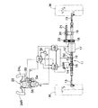
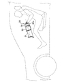
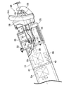
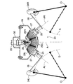
図1〜図6は本発明の一実施例を示すもので、図1は車両用操舵装置の全体図、図2は車両の前部側面図、図3は図2の要部拡大図、図4は図3に対応する斜視図、図5は図3の5−5線断面図、図6はハンドルを左旋回方向に操作したときの作用説明図である。 1 to 6 show an embodiment of the present invention. FIG. 1 is an overall view of a vehicle steering apparatus, FIG. 2 is a front side view of the vehicle, and FIG. 3 is an enlarged view of a main part of FIG. 4 is a perspective view corresponding to FIG. 3, FIG. 5 is a cross-sectional view taken along line 5-5 of FIG. 3, and FIG. 6 is an explanatory diagram of operation when the handle is operated in the left-turning direction.
図1に示すように、自動車の車輪W,Wを転舵するステアリングギヤボックス11は車体左右方向に摺動自在なラックバー12を備えており、ラックバー12の両端が左右のタイロッド13,13を介して左右の車輪W,Wに接続される。電気モータよりなる第1ステアリングアクチュエータ14により回転するピニオン15がラックバー12に形成したラック16に噛み合っており、第1ステアリングアクチュエータ14を駆動するとピニオン15およびラック16を介してラックバー12が車体左右方向に摺動し、タイロッド13,13を介して左右の車輪W,Wが転舵される。
As shown in FIG. 1, a
電気モータよりなる第2ステアリングアクチュエータ17と、それにより回転する環状のドライブギヤ18とがラックバー12の外周を囲むように配置される。ラックバー12に固定したブラケット19に支持した雌ねじ部材20に雄ねじ部材21が噛み合っており、この雄ねじ部材21の一端に設けたドリブンギヤ22が前記ドライブギヤ18に噛み合っている。従って、第2ステアリングアクチュエータ17を駆動すると、ドライブギヤ18の回転がドリブンギヤ22を介して雄ねじ部材21に伝達され、回転する雄ねじ部材21に噛み合う雌ねじ部材20が車体左右方向に移動することで、ラックバー12が車体左右方向に摺動して左右の車輪W,Wが転舵される。
A
図2〜図4に示すように、ステアリングハンドル23は、ドライバーが左手で握る左グリップ24Lと右手で握る右グリップ24Rとを備えており、左右のグリップ24L,24Rはドライバーに向かってV字状に傾斜した左右の自転軸AL,AR上に配置された左右の回転軸25,25の後端に板状のアーム26,26を介して固定され、各々の回転軸25,25はボールベアリング27,27で円形のハウジング28に自転自在に支持される。左右の回転軸25,25の対向する端部には左右のベベルギヤ29L,29Rがそれぞれ固定されており、左右のベベルギヤ29L,29Rは共通の固定ベベルギヤ29Cに噛合する。
As shown in FIGS. 2 to 4, the
ハウジング28に一体に固定された第1ステアリングシャフト30は、前部コラムカバー31の後端にボルト32…固定された後部コラムカバー33に一対のボールベアリング34,34を介して公転自在に支持される。後部コラムカバー33の下面に固定したステー35の後端に、前記固定ベベルギヤ29Cと一体の支軸36が固定される。従って、固定ベベルギヤ29Cは後部コラムカバー33に回転不能に支持される。そして左右のグリップ24L,24Rの自転軸AL,ARは、第1ステアリングシャフト30上にある公転軸Aに対して鋭角(実施例では35°)で交差している。つまり公転軸Aを挟んで左右の自転軸AL,ARは相互に70°の角度で交差している。
The
第1ステアリングシャフト30の前端にボルト37…で結合された第2ステアリングシャフト38が、前部コラムカバー31にボールベアリング42を介して回転自在に支持される。第2ステアリングシャフト38の前端部には、ドライバーがステアリングハンドル23に入力した操舵角δを検出する操舵角センサSaが設けられ、第2ステアリングシャフト38の中間部には、ドライバーがステアリングハンドル23に入力した操舵トルクTを検出する操舵トルクセンサSbが設けられる。また第2ステアリングシャフト38の中間部には操舵反力発生手段39が設けられる。操舵反力発生手段39は電気モータあるいは油圧によりステアリングハンドル23に擬似的な操舵反力を付与するもので、その出力軸に設けた駆動ギヤ40が第2ステアリングシャフト38に設けた従動ギヤ41に噛合することで操舵反力の方向および大きさを任意に制御可能である。
A
図1に示すように、第1ステアリングアクチュエータ14の作動は第1ステアリングアクチュエータ用電子制御ユニットUaにより制御され、第2ステアリングアクチュエータ17の作動は第2ステアリングアクチュエータ用電子制御ユニットUbにより制御され、操舵反力発生手段39の作動は操舵反力発生手段用電子制御ユニットUcにより制御される。
As shown in FIG. 1, the operation of the
第1、第2ステアリングアクチュエータ用電子制御ユニットUa,Ubには操舵角センサSaで検出した操舵角δと、車速センサScで検出した車速Vと、ラック位置センサSdで検出したラック位置Pとが入力され、操舵反力発生手段用電子制御ユニットUcには、操舵角センサSaで検出した操舵角δと、操舵トルクセンサSbで検出した操舵トルクTと、車速センサScで検出した車速Vとが入力される。 The first and second steering actuator electronic control units Ua and Ub have a steering angle δ detected by the steering angle sensor Sa, a vehicle speed V detected by the vehicle speed sensor Sc, and a rack position P detected by the rack position sensor Sd. The steering reaction force generating means electronic control unit Uc is inputted with the steering angle δ detected by the steering angle sensor Sa, the steering torque T detected by the steering torque sensor Sb, and the vehicle speed V detected by the vehicle speed sensor Sc. Entered.
次に、上記構成を備えた実施例の作用を説明する。 Next, the operation of the embodiment having the above configuration will be described.
第1ステアリングアクチュエータ14は通常時に使用され、第2ステアリングアクチュエータ17は、第1ステアリングアクチュエータ14の故障時のバックアップに使用される。第1ステアリングアクチュエータ14が正常に機能している通常時に、ドライバーがステアリングハンドル23を操作すると、第1ステアリングシャフト30の回転が第2ステアリングシャフト38に伝達され、第2ステアリングシャフト38に接続された操舵角センサSaおよび操舵トルクセンサSbによって操舵角δおよび操舵トルクTが検出される。
The
操舵角センサSaで検出した操舵角δと、車速センサScで検出した車速Vと、ラック位置センサSdで検出したラック位置Pとが第1ステアリングアクチュエータ用電子制御ユニットUaに入力される。第1ステアリングアクチュエータ用電子制御ユニットUaは、例えば、ステアリングハンドル23の操舵角δに比例した車輪W,Wの転舵角γが得られるように第1ステアリングアクチュエータ14を駆動し、ステアリングギヤボックス11を介して車輪W,Wを転舵する。
The steering angle δ detected by the steering angle sensor Sa, the vehicle speed V detected by the vehicle speed sensor Sc, and the rack position P detected by the rack position sensor Sd are input to the first steering actuator electronic control unit Ua. The electronic control unit Ua for the first steering actuator drives the
このとき、ラック位置センサSdで検出したラック位置P(つまり、車輪W,Wの転舵角γ)が目標位置に一致するようにフィードバック制御が行われる。また、例えば、車速センサScで検出した車速Vが大きいときには車輪W,Wの目標転舵角を減少させ、前記車速Vが小さいときには車輪W,Wの目標転舵角を増加させることで、高速時に車両の直進安定性を高めるとともに、低速時に車両の取り回しを容易にすることができる。 At this time, feedback control is performed so that the rack position P detected by the rack position sensor Sd (that is, the turning angle γ of the wheels W, W) matches the target position. For example, when the vehicle speed V detected by the vehicle speed sensor Sc is high, the target turning angle of the wheels W and W is decreased, and when the vehicle speed V is low, the target turning angle of the wheels W and W is increased. Sometimes, it is possible to improve the straight running stability of the vehicle and facilitate the handling of the vehicle at a low speed.
ステア・バイ・ワイヤ式操舵装置ではステアリングハンドル23に車輪W,Wからの操舵反力が作用しないため、操舵反力発生手段用電子制御ユニットUcからの指令で操舵反力発生手段39を駆動し、ステアリングハンドル23に操舵反力を付与する必要がある。その際の目標操舵反力は、操舵角センサSaで検出した操舵角δおよび車速センサScで検出した車速Vをパラメータとしてマップ検索される。このマップは、操舵角δが大きくなるほど操舵反力が大きくなり、かつ車速Vが大きくなるほど操舵反力が大きくなるように設定される。そして操舵トルクセンサSbで検出した操舵トルクTが前記目標操舵反力に一致するように、操舵反力発生手段39の駆動がフィードバック制御される。このように、操舵反力発生手段39でステアリングハンドル23に擬似的な操舵反力を付与することで、ドライバーの違和感を解消することができる。
In the steer-by-wire type steering device, since the steering reaction force from the wheels W, W does not act on the
また第1ステアリングアクチュエータ14の故障時には、第2ステアリングアクチュエータ用電子制御ユニットUbが第2ステアリングアクチュエータ17を同様に制御することで、車輪W,Wの転舵を支障なく継続することができる。
When the
さて、図6(A)に示すニュートラル状態から、図6(B)に示すように、ステアリングハンドル23を公転軸Aまわりに左旋回方向に操作すると、左グリップ24Lは自転軸ALまわりに反時計方向に自転し、また右グリップ24Rも自転軸ARまわりに反時計方向に自転する。
Now, from the neutral state shown in FIG. 6 (A), as shown in FIG. 6 (B), when the steering handle 23 is operated in the left turning direction around the revolution axis A, the
このようにステアリングハンドル23を公転軸Aまわりに左旋回方向に公転させると、左右のグリップ24L,24Rが自転軸AL,ARまわりに相互に連動して同方向に自転するため、ドライバーの左右の手首は自然に捻られて無理な角度にならず、ドライバーのステアリング操作が容易になる。そして図6(C)に示すように、ステアリングハンドル23の公転軸Aまわりに限界回転角は90°に抑えられる。また左右のグリップ24L,24Rの連動機構を左右のベベルギヤ29L,29Rおよび固定ベベルギヤ29Cで構成したので、簡単な構造で左右のグリップ24L,24Rを相互に連動して同方向に自転させることができる。
When the steering handle 23 is revolved in the left turning direction around the revolution axis A in this way, the left and
また左右の自転軸AL,ARがドライバー側に向かってV字状に広がるように傾斜しているため、左右のグリップ24L,24Rは中立位置から上方に移動するときにドライバーに近づく方向に移動し、図5に示すように、左右のグリップ24L,24Rはドライバーの肘の位置O,Oを中心とする球面S,S上を移動することになる。これにより、ドライバーは肘の位置を固定したまま、腕の肘から先の部分および手だけを動かしてステアリングハンドル23を操作することが可能になり、ステアリング操作が一層容易になる。
In addition, since the left and right rotation axes AL and AR are inclined so as to spread in a V shape toward the driver, the left and
ここまでステアリングハンドル23を左旋回方向に操作する場合について説明したが、ステアリングハンドル23を右旋回方向に操作する場合の作用も同じである。 Although the case where the steering handle 23 is operated in the left turning direction has been described so far, the operation when the steering handle 23 is operated in the right turning direction is the same.
以上、本発明の実施例を説明したが、本発明はその要旨を逸脱しない範囲で種々の設計変更を行うことが可能である。 The embodiments of the present invention have been described above, but various design changes can be made without departing from the scope of the present invention.
例えば、実施例では左右のグリップ24L,24Rの自転軸AL,ARは相互に70°をなしているが、その角度は70°に限定されるものではない。
For example, in the embodiment, the rotation axes AL and AR of the left and
14 第1ステアリングアクチュエータ(アクチュエータ)
17 第2ステアリングアクチュエータ(アクチュエータ)
24L 左グリップ(操作部材)
24R 右グリップ(操作部材)
A 公転軸
AL 自転軸
AR 自転軸
O ドライバーの肘の位置
S 球面
Ua 第1ステアリングアクチュエータ用電子制御ユニット(制御手段)
Ub 第2ステアリングアクチュエータ用電子制御ユニット(制御手段)
W 車輪
14 First steering actuator (actuator)
17 Second steering actuator (actuator)
24L Left grip (operation member)
24R Right grip (operating member)
A Revolving axis AL Rotating axis AR Rotating axis O Position of driver's elbow S Spherical surface Ua Electronic control unit for first steering actuator (control means)
Ub Second steering actuator electronic control unit (control means)
W wheel
Claims (3)
車輪(W)を転舵するアクチュエータ(14,17)と、
前記操作部材(24L,24R)の操作に応じて前記アクチュエータ(14,17)の作動を制御する制御手段(Ua,Ub)と、
を備えた車両用操舵装置において、
ドライバーの操作による前記操作部材(24L,24R)の移動軌跡は、ドライバーの肘の位置(O)を中心とする球面(S)上に在ることを特徴とする車両用操舵装置。 Left and right operation members (24L, 24R) that the driver operates by grasping with left and right hands,
Actuators (14, 17) for turning the wheels (W);
Control means (Ua, Ub) for controlling the operation of the actuator (14, 17) in accordance with the operation of the operation member (24L, 24R);
In a vehicle steering apparatus comprising:
The vehicle steering apparatus, wherein a movement locus of the operation member (24L, 24R) by a driver's operation is on a spherical surface (S) centered on a position (O) of the driver's elbow.
車輪(W)を転舵するアクチュエータ(14,17)と、
前記操作部材(24L,24R)の操作に応じて前記アクチュエータ(14,17)の作動を制御する制御手段(Ua,Ub)と、
を備えた車両用操舵装置において、
操作部材(24L,24R)は、中立位置から上方に移動するときにドライバーに近づく方向に移動することを特徴とする車両用操舵装置。 Left and right operation members (24L, 24R) that the driver operates by grasping with left and right hands,
Actuators (14, 17) for turning the wheels (W);
Control means (Ua, Ub) for controlling the operation of the actuator (14, 17) in accordance with the operation of the operation member (24L, 24R);
In a vehicle steering apparatus comprising:
The vehicle steering apparatus, wherein the operating members (24L, 24R) move in a direction approaching the driver when moving upward from the neutral position.
車輪(W)を転舵するアクチュエータ(14,17)と、
前記操作部材(24L,24R)の操作に応じて前記アクチュエータ(14,17)の作動を制御する制御手段(Ua,Ub)と、
を備えた車両用操舵装置において、
左右の操作部材(24L,24R)は公転軸(A)まわりに公転しながら左右の自転軸(AL,AR)まわりに自転可能であり、前記左右の自転軸(AL,AR)はドライバーに向かってV字状に開くように傾斜していることを特徴とする車両用操舵装置。
Left and right operation members (24L, 24R) that the driver operates by grasping with left and right hands,
Actuators (14, 17) for turning the wheels (W);
Control means (Ua, Ub) for controlling the operation of the actuator (14, 17) in accordance with the operation of the operation member (24L, 24R);
In a vehicle steering apparatus comprising:
The left and right operation members (24L, 24R) can rotate about the left and right rotation axes (AL, AR) while revolving around the rotation axis (A), and the left and right rotation axes (AL, AR) face the driver. And a vehicle steering device that is inclined so as to open in a V shape.
Priority Applications (6)
| Application Number | Priority Date | Filing Date | Title |
|---|---|---|---|
| JP2004116872A JP4191643B2 (en) | 2004-04-12 | 2004-04-12 | Vehicle steering system |
| PCT/JP2004/015586 WO2005054032A1 (en) | 2003-12-01 | 2004-10-21 | Steering handle and steering device |
| US10/580,920 US7726692B2 (en) | 2003-12-01 | 2004-10-21 | Steering handle and steering system |
| EP04792736A EP1690774A4 (en) | 2003-12-01 | 2004-10-21 | Steering handle and steering device |
| TW093133894A TWI265117B (en) | 2003-12-01 | 2004-11-05 | Steering handle and steering device |
| MYPI20044924A MY146347A (en) | 2003-12-01 | 2004-11-29 | Steering handle and steering system |
Applications Claiming Priority (1)
| Application Number | Priority Date | Filing Date | Title |
|---|---|---|---|
| JP2004116872A JP4191643B2 (en) | 2004-04-12 | 2004-04-12 | Vehicle steering system |
Publications (2)
| Publication Number | Publication Date |
|---|---|
| JP2005297772A true JP2005297772A (en) | 2005-10-27 |
| JP4191643B2 JP4191643B2 (en) | 2008-12-03 |
Family
ID=35329843
Family Applications (1)
| Application Number | Title | Priority Date | Filing Date |
|---|---|---|---|
| JP2004116872A Expired - Fee Related JP4191643B2 (en) | 2003-12-01 | 2004-04-12 | Vehicle steering system |
Country Status (1)
| Country | Link |
|---|---|
| JP (1) | JP4191643B2 (en) |
Cited By (7)
| Publication number | Priority date | Publication date | Assignee | Title |
|---|---|---|---|---|
| JP2007276516A (en) * | 2006-04-03 | 2007-10-25 | Honda Motor Co Ltd | Steering device |
| JP2007297021A (en) * | 2006-05-08 | 2007-11-15 | Toyota Motor Corp | Vehicle steering system |
| JP2009196462A (en) * | 2008-02-20 | 2009-09-03 | Honda Motor Co Ltd | Steering device |
| JP2014043147A (en) * | 2012-08-24 | 2014-03-13 | Toyota Central R&D Labs Inc | Steering device |
| DE102016225452A1 (en) * | 2016-12-19 | 2018-06-21 | Bayerische Motoren Werke Aktiengesellschaft | Steering device for a vehicle |
| KR101858398B1 (en) * | 2017-07-18 | 2018-06-27 | 고려대학교 산학협력단 | Variable steering handle device |
| JP2022154638A (en) * | 2021-03-30 | 2022-10-13 | 豊田合成株式会社 | steering handle |
-
2004
- 2004-04-12 JP JP2004116872A patent/JP4191643B2/en not_active Expired - Fee Related
Cited By (9)
| Publication number | Priority date | Publication date | Assignee | Title |
|---|---|---|---|---|
| JP2007276516A (en) * | 2006-04-03 | 2007-10-25 | Honda Motor Co Ltd | Steering device |
| JP2007297021A (en) * | 2006-05-08 | 2007-11-15 | Toyota Motor Corp | Vehicle steering system |
| JP2009196462A (en) * | 2008-02-20 | 2009-09-03 | Honda Motor Co Ltd | Steering device |
| JP2014043147A (en) * | 2012-08-24 | 2014-03-13 | Toyota Central R&D Labs Inc | Steering device |
| DE102016225452A1 (en) * | 2016-12-19 | 2018-06-21 | Bayerische Motoren Werke Aktiengesellschaft | Steering device for a vehicle |
| KR101858398B1 (en) * | 2017-07-18 | 2018-06-27 | 고려대학교 산학협력단 | Variable steering handle device |
| JP2022154638A (en) * | 2021-03-30 | 2022-10-13 | 豊田合成株式会社 | steering handle |
| US11608103B2 (en) | 2021-03-30 | 2023-03-21 | Toyoda Gosei Co., Ltd. | Steering wheel |
| JP7444122B2 (en) | 2021-03-30 | 2024-03-06 | 豊田合成株式会社 | steering handle |
Also Published As
| Publication number | Publication date |
|---|---|
| JP4191643B2 (en) | 2008-12-03 |
Similar Documents
| Publication | Publication Date | Title |
|---|---|---|
| US7726692B2 (en) | Steering handle and steering system | |
| JP4252888B2 (en) | Steering handle for vehicles | |
| EP3934963B1 (en) | Apparatus for use in turning steerable vehicle wheels | |
| US11945531B2 (en) | Steering device | |
| JP2005041283A (en) | Steering control device | |
| US6695092B2 (en) | Steering actuator system | |
| JP4191643B2 (en) | Vehicle steering system | |
| JP2000016316A (en) | Steering device for vehicle | |
| JPH05105103A (en) | Electric power steering device | |
| JP2005329864A (en) | Vehicle steering system | |
| JP2002337717A (en) | Electric power steering device | |
| JP5226999B2 (en) | Vehicle steering device | |
| JP2008201155A (en) | Steering device | |
| JP5001715B2 (en) | Steering device | |
| US20190111963A1 (en) | Compact steering | |
| JP4803338B2 (en) | Vehicle steering device | |
| JP3966859B2 (en) | Cable-type steering device | |
| JP2006175925A (en) | Vehicle steering system | |
| JPH092295A (en) | Vehicle steering system | |
| JP3024454B2 (en) | Vehicle steering system | |
| JP2539097Y2 (en) | Electric power steering device | |
| JPH0525709B2 (en) | ||
| JP5157226B2 (en) | Vehicle steering system | |
| JPH0321336Y2 (en) | ||
| JP2005145254A (en) | Vehicle steering device |
Legal Events
| Date | Code | Title | Description |
|---|---|---|---|
| A621 | Written request for application examination |
Free format text: JAPANESE INTERMEDIATE CODE: A621 Effective date: 20061128 |
|
| A131 | Notification of reasons for refusal |
Free format text: JAPANESE INTERMEDIATE CODE: A131 Effective date: 20080521 |
|
| A521 | Request for written amendment filed |
Free format text: JAPANESE INTERMEDIATE CODE: A523 Effective date: 20080702 |
|
| TRDD | Decision of grant or rejection written | ||
| A01 | Written decision to grant a patent or to grant a registration (utility model) |
Free format text: JAPANESE INTERMEDIATE CODE: A01 Effective date: 20080903 |
|
| A01 | Written decision to grant a patent or to grant a registration (utility model) |
Free format text: JAPANESE INTERMEDIATE CODE: A01 |
|
| A61 | First payment of annual fees (during grant procedure) |
Free format text: JAPANESE INTERMEDIATE CODE: A61 Effective date: 20080918 |
|
| FPAY | Renewal fee payment (event date is renewal date of database) |
Free format text: PAYMENT UNTIL: 20110926 Year of fee payment: 3 |
|
| R150 | Certificate of patent or registration of utility model |
Free format text: JAPANESE INTERMEDIATE CODE: R150 |
|
| LAPS | Cancellation because of no payment of annual fees |