JP2005297724A - Hydrogen tank support device and method for fuel cell vehicle - Google Patents
Hydrogen tank support device and method for fuel cell vehicle Download PDFInfo
- Publication number
- JP2005297724A JP2005297724A JP2004115793A JP2004115793A JP2005297724A JP 2005297724 A JP2005297724 A JP 2005297724A JP 2004115793 A JP2004115793 A JP 2004115793A JP 2004115793 A JP2004115793 A JP 2004115793A JP 2005297724 A JP2005297724 A JP 2005297724A
- Authority
- JP
- Japan
- Prior art keywords
- hydrogen tank
- container
- fuel cell
- impact
- cell vehicle
- Prior art date
- Legal status (The legal status is an assumption and is not a legal conclusion. Google has not performed a legal analysis and makes no representation as to the accuracy of the status listed.)
- Withdrawn
Links
Images


Classifications
-
- Y—GENERAL TAGGING OF NEW TECHNOLOGICAL DEVELOPMENTS; GENERAL TAGGING OF CROSS-SECTIONAL TECHNOLOGIES SPANNING OVER SEVERAL SECTIONS OF THE IPC; TECHNICAL SUBJECTS COVERED BY FORMER USPC CROSS-REFERENCE ART COLLECTIONS [XRACs] AND DIGESTS
- Y02—TECHNOLOGIES OR APPLICATIONS FOR MITIGATION OR ADAPTATION AGAINST CLIMATE CHANGE
- Y02E—REDUCTION OF GREENHOUSE GAS [GHG] EMISSIONS, RELATED TO ENERGY GENERATION, TRANSMISSION OR DISTRIBUTION
- Y02E60/00—Enabling technologies; Technologies with a potential or indirect contribution to GHG emissions mitigation
- Y02E60/30—Hydrogen technology
- Y02E60/50—Fuel cells
Landscapes
- Cooling, Air Intake And Gas Exhaust, And Fuel Tank Arrangements In Propulsion Units (AREA)
- Vibration Prevention Devices (AREA)
- Fuel Cell (AREA)
Abstract
【課題】 燃料電池車のさらなる衝突安全性を高め、事故などに遭遇した場合でも、水素タンクの破損、破壊を招くことがなく、かつ燃料電池車の大幅な性能低下、あるいは高額化をきたすことのない燃料電池自動車の水素タンク支持装置及び方法を提供する。
【解決手段】 水素タンク13を強度を有する容器11の内部に、同容器の内壁面に対して適当な隔離距離を設けて固定し、同容器がある規定値以上の衝撃を受けた場合に同固定部14が切断されるような構造又は強度とし、前記容器の内壁面を、前記水素タンクが前記規定値以上の衝撃を受けて前記固定部が切断した後、前記水素タンクが同内壁面に衝突して減衰振動を起こす構造としたことを特徴とする。
【選択図】 図2PROBLEM TO BE SOLVED: To further improve the collision safety of a fuel cell vehicle, so that even if an accident is encountered, the hydrogen tank is not damaged or destroyed, and the performance of the fuel cell vehicle is greatly reduced or expensive. An apparatus and method for supporting a hydrogen tank of a fuel cell vehicle without a fuel cell are provided.
SOLUTION: A hydrogen tank 13 is fixed inside a strong container 11 with an appropriate separation distance from the inner wall surface of the container, and the same is applied when the container receives an impact exceeding a predetermined value. The structure or strength is such that the fixing portion 14 is cut, and the hydrogen tank is placed on the inner wall surface of the container after the hydrogen tank receives an impact greater than the specified value and the fixing portion is cut. It is characterized by a structure that causes a damped vibration upon collision.
[Selection] Figure 2
Description
本発明は、燃料電池自動車が事故を起こした場合など、燃料電池自動車に搭載されている高圧水素タンクにきわめて大きな衝撃が加わった場合においても、高圧水素タンクの破損、破壊を確実に防止し得る水素タンクの支持装置及び方法に関する。 The present invention can reliably prevent the high-pressure hydrogen tank from being damaged or destroyed even when a very large impact is applied to the high-pressure hydrogen tank mounted on the fuel cell automobile, such as when an accident occurs in the fuel cell automobile. The present invention relates to a hydrogen tank support apparatus and method.
最近開発が急ピッチで進められている燃料電池自動車において、その水素貯蔵方式は、高圧水素タンクのほか、水素吸蔵合金タンクや液体水素タンクに貯蔵する方式が考えられるが、現時点では、高圧水素タンク方式が主流となっている。 Recently, fuel cell vehicles that are being developed at a rapid pace can be stored in hydrogen storage alloy tanks or liquid hydrogen tanks as well as high-pressure hydrogen tanks. The method is mainstream.
燃料電池車の衝突時の水素タンクの安全性を高めるため種々の方策がなされており、そのひとつとして、たとえば、次の3層からなる3シールド積層構造の高強度の水素タンクが採用されている。
(1)軽量の高分子材料で、水素の気密を保つ層
(2)抗張力鋼の数倍の高強度カーボンファイバーで高圧下での強度を完全に保持する層
(3)表層にケブラー系高弾性繊維により、事故などの際に異物がぶつかった際の衝撃を吸収する層
また衝突時には、すべての高圧電気回路と水素元バルブを遮断するシステムも採用されている。
Various measures have been taken to enhance the safety of hydrogen tanks in the event of a fuel cell vehicle collision. For example, a high-strength hydrogen tank having a three-shield laminated structure consisting of the following three layers is adopted. .
(1) Light-weight polymer material that keeps hydrogen tight. (2) High-strength carbon fiber several times stronger than high-strength steel. Fully maintains strength under high pressure. (3) Kevlar high elasticity on the surface layer. A layer that absorbs shock when a foreign object collides with an accident in the event of an accident. In addition, a system that shuts off all high-voltage electric circuits and hydrogen source valves in the event of a collision is also used.
また、特許文献1(特開2003−211982号公報)においては、高圧水素タンクと水素が供給される燃料電池とを高圧水素配管及び低圧水素配管で接続し、高圧水素配管には衝撃によって閉じる電磁弁及び高圧水素を低圧水素に減圧する調圧弁が介装され、調圧弁より下流側の低圧水素配管には脆弱部を設け、車両衝突時などに車体が変形しても、このとき発生する応力を低圧水素配管の脆弱部が受けて変形により吸収し、高圧水素配管の変形を防止するとともに、車両衝突時などに前記電磁弁を閉じることで、脆弱部への水素の供給が停止され、脆弱部で破損が生じたとしても、水素タンク内の燃料の漏れを防止する水素配管構造が記載されている。 Moreover, in patent document 1 (Unexamined-Japanese-Patent No. 2003-211982), the high pressure hydrogen tank and the fuel cell supplied with hydrogen are connected by a high pressure hydrogen pipe and a low pressure hydrogen pipe, and the high pressure hydrogen pipe is closed by an impact. The valve and a pressure regulating valve that depressurizes high-pressure hydrogen to low-pressure hydrogen are installed, and the low-pressure hydrogen piping downstream from the pressure regulating valve is provided with a fragile part. The fragile part of the low-pressure hydrogen pipe receives and absorbs by deformation, preventing deformation of the high-pressure hydrogen pipe, and closing the solenoid valve at the time of a vehicle collision, etc., stops the supply of hydrogen to the fragile part, A hydrogen piping structure that prevents leakage of fuel in the hydrogen tank is described even if damage occurs in the part.
しかしながら上記の従来の衝突時の対策では、ある程度の衝撃に対しては有効であるかもしれないが、燃料電池車が、事故等により大きな衝撃を受けた場合、上記の手段では不十分な場合もある。 However, the above-mentioned conventional countermeasures at the time of a collision may be effective against a certain degree of impact, but if the fuel cell vehicle receives a large impact due to an accident or the like, the above means may not be sufficient. is there.
本発明は、かかる従来技術の課題に鑑み、燃料電池車のさらなる衝突時の安全性を高め、事故などに遭遇した場合、あるいは車体が崖から転落したような場合でも、水素の引火を引き起こすような水素タンクの破損、破壊を招くことがなく、かつ燃料電池車の大幅な性能低下、あるいは構造の複雑化をまねくことのない燃料電池自動車の水素タンク支持装置及び方法を提供することを目的とする。 In view of the problems of the prior art, the present invention increases the safety at the time of further collision of the fuel cell vehicle, and causes ignition of hydrogen even when an accident or the like is encountered or the vehicle body falls from a cliff. An object of the present invention is to provide a hydrogen tank support device and method for a fuel cell vehicle that does not cause damage or destruction of the hydrogen tank and that does not significantly reduce the performance of the fuel cell vehicle or complicate the structure. To do.
本発明はかかる目的を達成するもので、その第1の手段は、水素タンクを強度を有する容器の内部に、同容器の内壁面に対して適当な隔離距離を設けて固定し、同容器がある規定値以上の衝撃を受けた場合に同固定部が切断されるような構造又は強度とし、前記容器の内壁面を、前記水素タンクが前記規定値以上の衝撃を受けて前記固定部が切断した後、前記水素タンクが同内壁面に衝突して減衰振動を起こす構造としたことを特徴とする。
かかる第1の手段において、好ましくは、前記固定部を割りピン構造とする。また別な好ましい実施形態としては、前記固定部を弾性体で構成し、前記水素タンクを弾力性をもって支持するようにする。さらに別な好ましい実施形態としては、前記容器の内壁面に、ケブラー系高弾性繊維をコーティングした炭素繊維層を貼り付ける。
The present invention achieves such an object, and the first means is that a hydrogen tank is fixed inside a strong container with an appropriate separation distance from the inner wall surface of the container. Structure or strength so that the fixed part is cut when an impact exceeding a specified value is applied, and the inner wall surface of the container is cut when the hydrogen tank receives an impact exceeding the specified value. Then, the hydrogen tank collides with the inner wall surface to cause a damped vibration.
In the first means, preferably, the fixing portion has a split pin structure. In another preferred embodiment, the fixing portion is made of an elastic body, and the hydrogen tank is elastically supported. As another preferred embodiment, a carbon fiber layer coated with Kevlar high-elasticity fibers is attached to the inner wall surface of the container.
かかる第1の手段においては、前記固定部が耐え得るある規定以上の衝撃力を受けるまでは、水素タンクは容器内で固定され、ある規定以上の衝撃力を受けた場合、水素タンクの前記固定部が切断し、水素タンクが前記容器の中で容器の内壁面と衝突を繰り返しながら、衝撃を吸収し、減衰振動する。そのため水素タンクの破損、破断には至らない。 In the first means, the hydrogen tank is fixed in the container until an impact force exceeding a specified value that the fixing part can withstand, and when the impact force exceeds a specified value, the hydrogen tank is fixed. The part is cut, and the hydrogen tank absorbs an impact and oscillates and oscillates while repeatedly colliding with the inner wall surface of the container. Therefore, the hydrogen tank does not break or break.
その際固定部を割りピン構造とすれば、簡単な構造で、固定部が切断する衝撃力を正確に設定できる。また固定部を弾性体で構成し、前記水素タンクを弾力性をもって支持すれば、固定部が切断されるまでの衝撃吸収力をさらに向上できる。また容器の内壁面に、ケブラー系高弾性繊維をコーティングした炭素繊維層を貼り付けるようにすれば、最も軽量で高強度の高圧容器とすることができるとともに、固定部が切断した後の減衰振動の効果も格段に向上できる。 At this time, if the fixing portion has a split pin structure, the impact force that the fixing portion cuts can be accurately set with a simple structure. Further, if the fixing portion is made of an elastic body and the hydrogen tank is supported with elasticity, the impact absorbing force until the fixing portion is cut can be further improved. In addition, if a carbon fiber layer coated with Kevlar high-elasticity fibers is affixed to the inner wall surface of the container, it can be made the lightest and most powerful high-pressure container, and the damped vibration after the fixed part is cut The effect of can also be improved significantly.
また、本発明の第2の手段は、水素タンクの支持方法として、水素タンクを強度を有する容器の内部に、同容器の内壁面に対して適当な隔離距離を設けて固定し、同水素タンクがある規定値以上の衝撃を受けた場合に同固定部が切断されるような構造又は強度とし、前記容器が前記規定値以上の衝撃を受けて前記固定部が切断した後、同容器の内部で前記水素タンクに減衰振動を起させて、衝撃を吸収させることを特徴とする。
係る方法として、好ましくは、前記水素タンクを囲む前記容器内の空間部に衝撃緩衝材を充填する。
Further, the second means of the present invention is a method for supporting the hydrogen tank, wherein the hydrogen tank is fixed inside the strong container with an appropriate separation distance from the inner wall surface of the container. It is structured or strength so that the fixed part is cut when an impact exceeding a specified value is received, and after the container receives an impact greater than the specified value and the fixed part is cut, the inside of the container In this case, the hydrogen tank is caused to dampen to absorb shock.
As such a method, preferably, a shock absorbing material is filled in a space portion in the container surrounding the hydrogen tank.
かかる方法によれば、同水素タンクがある規定値以上の衝撃を受け、水素タンクを容器に固定する固定部が切断した場合でも、容器の内部で水素タンクが減衰振動を起こし、衝撃を吸収するので、水素タンクが破損、破断するまでには至らない。
減衰運動を起こすための具体的な手段としては、たとえば容器の内部に気泡を含んだ発泡スチロールなどの衝撃吸収材を充填すれば、簡単かつ安価な構造で、大幅な改造等を要することなく、大きな減衰効果が得られる。
According to this method, even when the hydrogen tank receives an impact exceeding a predetermined value and the fixing part that fixes the hydrogen tank to the container is cut, the hydrogen tank causes a damped vibration inside the container and absorbs the shock. Therefore, the hydrogen tank is not broken or broken.
As a specific means for causing the damping motion, for example, if the inside of the container is filled with an impact absorbing material such as foamed polystyrene containing air bubbles, it is a simple and inexpensive structure, and does not require significant modification. A damping effect is obtained.
本発明の第3の手段は、水素タンクの両端にある固定部をガイド部材に摺動可能に嵌合し、同ガイド部材の両端にそれぞれ一端が取り付けられ、他端にストッパーを取り付けた一対のダンパースプリングによって、前記固定部をストッパーを介し両側から付勢するようにしたことを特徴とする。
この構成により、前記固定部が切断されない間は、前記ガイド部材が水素タンクを摺動可能にガイドする方向に沿った衝撃に対して、優れた吸収性能が発揮される。
According to a third means of the present invention, a pair of fixed portions at both ends of the hydrogen tank are slidably fitted to the guide member, one end is attached to each end of the guide member, and a stopper is attached to the other end. The fixed portion is urged from both sides via a stopper by a damper spring.
With this configuration, while the fixing portion is not cut, an excellent absorption performance is exhibited against an impact along the direction in which the guide member slidably guides the hydrogen tank.
以上のように、本発明によれば、水素タンクを強度を有する容器の内部に、同容器の内壁面に対して適当な隔離距離を設けて固定し、同容器がある規定値以上の衝撃を受けた場合に同固定部が切断されるような構造又は強度とし、前記容器の内壁面を、前記水素タンクが前記規定値以上の衝撃を受けて前記固定部が切断した後、前記水素タンクが同内壁面に衝突して減衰振動を起こす構造としたことにより、容器が規定値を越す大きな衝撃を受けた場合でも、水素タンクに減衰振動を起こして衝撃を吸収することができ、そのため水素タンク自体の破損、破断に至ることはなく、水素タンクへの引火等の危険を招くことはない。 As described above, according to the present invention, a hydrogen tank is fixed inside a strong container with an appropriate separation distance from the inner wall surface of the container, and the container is subjected to an impact exceeding a specified value. The structure is such that the fixing portion is cut when it is received, or the strength, and the inner wall surface of the container is cut after the fixing portion is cut by the hydrogen tank receiving an impact of the specified value or more. By adopting a structure that causes damping vibration by colliding with the inner wall surface, even if the container receives a large impact exceeding the specified value, it can absorb the shock by causing a damping vibration in the hydrogen tank. It does not lead to breakage or breakage of itself and does not pose a danger of ignition to the hydrogen tank.
またその際、固定部を割りピン構造とすれば、固定部が切断する衝撃力を正確に設定できるとともに、構造が簡単で安価となる。さらに固定部の構成により、切断可能な衝撃力の方向を選定でき、必要とあれば、全周方向に対する衝撃に対して、衝撃吸収力を発揮できるような構造とすることも可能である。
また固定部を弾性体で構成し、前記水素タンクを弾力性をもって支持すれば、固定部が切断されるまでは、衝撃吸収力を向上できる。また容器の内壁面に、ケブラー系高弾性繊維をコーティングした炭素繊維層を貼り付けるようにすれば、ケブラー系高弾性繊維の高弾性特質を生かして、減衰効果を飛躍的に向上できるとともに、最も軽量で高強度の高圧容器とすることができる、等の長所がある。
In this case, if the fixing portion has a split pin structure, the impact force that the fixing portion cuts can be set accurately, and the structure is simple and inexpensive. Further, the direction of the impact force that can be cut can be selected depending on the configuration of the fixing portion, and if necessary, a structure capable of exhibiting the impact absorbing force with respect to the impact in the entire circumferential direction can be provided.
Further, if the fixing portion is made of an elastic body and the hydrogen tank is supported with elasticity, the impact absorbing power can be improved until the fixing portion is cut. In addition, if a carbon fiber layer coated with Kevlar high-elasticity fibers is attached to the inner wall surface of the container, the damping effect can be dramatically improved by taking advantage of the high-elastic properties of Kevlar high-elasticity fibers, and the most There are advantages such as a light-weight and high-strength high-pressure vessel.
また本発明の防護方法として、水素タンクを強度を有する容器の内部に、同容器の内壁面に対して適当な隔離距離を設けて固定し、同水素タンクがある規定値以上の衝撃を受けた場合に同固定部が切断されるような構造又は強度とし、前記容器が前記規定値以上の衝撃を受けて前記固定部が切断した後、同容器の内部で前記水素タンクに減衰振動を起させて、衝撃を吸収させることにより、上記の本発明装置と同様に、高い衝撃吸収能力を有し、水素タンクの破損、破断を招くことがない。
また水素タンクを囲む前記容器内の空間部に、たとえば容器の内部に気泡を含んだ発泡スチロールなどの衝撃吸収材を充填すれば、簡単かつ安価で大きな衝撃吸収効果が得られる。
As a protection method of the present invention, the hydrogen tank is fixed inside a strong container with an appropriate separation distance from the inner wall surface of the container, and the hydrogen tank receives an impact exceeding a predetermined value. In such a case, the fixed part is cut or structured so that the container is subjected to an impact of the specified value or more and the fixed part is cut, and then the damped vibration is caused in the hydrogen tank inside the container. Thus, by absorbing the impact, similarly to the above-described device of the present invention, it has a high impact absorption capability and does not cause damage or breakage of the hydrogen tank.
Further, if the space in the container surrounding the hydrogen tank is filled with a shock absorbing material such as foamed polystyrene containing bubbles inside the container, a large shock absorbing effect can be obtained easily and inexpensively.
本発明の第3の手段として、水素タンクの両端にある固定部をガイド部材に摺動可能に嵌合し、同ガイド部材の両端にそれぞれ一端が取り付けられ、他端にストッパーを取り付けた一対のダンパースプリングによって、前記固定部をストッパーを介し両側から付勢するようにしたことにより、簡易な構造で、特に、前記固定部が切断されない間は、前記ガイド部材が水素タンクを摺動可能にガイドする方向に沿った衝撃に対して、優れた吸収性能が発揮される。 As a third means of the present invention, a pair of fixed portions at both ends of the hydrogen tank are slidably fitted to the guide member, one end is attached to each end of the guide member, and a stopper is attached to the other end. The damper spring urges the fixed part from both sides via a stopper, so that the guide member can slide the hydrogen tank in a simple structure, particularly when the fixed part is not cut. Excellent absorption performance is exhibited with respect to the impact along the direction.
以下、本発明を図に示した実施例を用いて詳細に説明する。但し、この実施例に記載されている構成部品の寸法、材質、形状、その相対配置などは特に特定的な記載がない限り、この発明の範囲をそれのみに限定する趣旨ではなく、単なる説明例にすぎない。
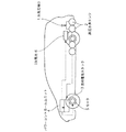
図1は高圧水素タンクを搭載した燃料電池自動車の説明図、図2は本発明の第1実施例に係る高圧水素タンクの支持装置の縦断面図、図3の(a)及び(b)は前記第1実施例に係る遮断部15の具体例を示す断面図、図4は本発明の第3実施例に係る高圧水素タンクの支持装置の斜視図、図5の(a)及び(b)は本発明の第3実施例に係る高圧水素タンクの支持装置の平面図及び左側面図である。
Hereinafter, the present invention will be described in detail with reference to the embodiments shown in the drawings. However, the dimensions, materials, shapes, relative arrangements, and the like of the component parts described in this example are not intended to limit the scope of the present invention only to specific examples unless otherwise specified. Only.
FIG. 1 is an explanatory view of a fuel cell vehicle equipped with a high-pressure hydrogen tank, FIG. 2 is a longitudinal sectional view of a supporting device for a high-pressure hydrogen tank according to the first embodiment of the present invention, and FIGS. FIG. 4 is a cross-sectional view showing a specific example of the blocking portion 15 according to the first embodiment, FIG. 4 is a perspective view of a support device for a high-pressure hydrogen tank according to a third embodiment of the present invention, and FIGS. These are the top view and left view of the support apparatus of the high pressure hydrogen tank which concern on 3rd Example of this invention.
高圧水素タンクを搭載した燃料電池自動車を示す図1において、1は、車体の後方下部に設けられた高圧水素タンク2に水素を供給する水素充填口であり、水素タンク2に貯蔵された水素は、車体の前輪付近に設けられた燃料電池スタック3に送られる。燃料電池スタックで発生した電気は、パワーコントロールユニット4の指令に従って、車輪を駆動するモータ5、及び2次電池6に供給される。 In FIG. 1 showing a fuel cell vehicle equipped with a high-pressure hydrogen tank, reference numeral 1 denotes a hydrogen filling port for supplying hydrogen to a high-pressure hydrogen tank 2 provided at the rear lower part of the vehicle body. Hydrogen stored in the hydrogen tank 2 is The fuel cell stack 3 is provided near the front wheel of the vehicle body. Electricity generated in the fuel cell stack is supplied to the motor 5 that drives the wheels and the secondary battery 6 in accordance with a command from the power control unit 4.
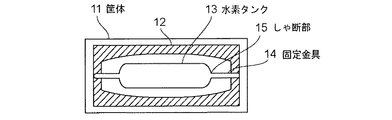
図2は、本発明の第1実施例に係る高圧水素タンクの防護装置の縦断面図であり、図2において、11はケブラー系高弾性繊維層12で内張りされた高強度カーボンファイバー製の筐体で、同筐体11の内部に、前述の3層シールド積層構造を有する高圧水素タンク13が、固定金具14により、筐体11の内壁面から適当な隔離距離を設けて固定されている。
固定金具14は、衝撃がある既定値を越えると切断する遮断部15を有し、そのためある既定値以上の衝撃を受けると、水素タンク13は筐体11から切り離されて、筐体11内で、筐体11の内壁面に衝突を繰り返しながら、減衰振動をすることで、衝撃を吸収していく。
FIG. 2 is a longitudinal sectional view of the high-pressure hydrogen tank protection device according to the first embodiment of the present invention. In FIG. 2, reference numeral 11 denotes a high-strength carbon fiber casing lined with a Kevlar high-
The fixing bracket 14 has a blocking portion 15 that is cut when an impact exceeds a predetermined value. Therefore, when the impact exceeds a predetermined value, the hydrogen tank 13 is separated from the housing 11 and is separated in the housing 11. The shock is absorbed by making a damped vibration while repeatedly colliding with the inner wall surface of the casing 11.
かかる第1実施例において、ある既定値以上の衝撃を受けると、水素タンク13は筐体11から切り離されて、筐体11内で、筐体11の内壁面に衝突を繰り返しながら、減衰振動をすることで、衝撃を吸収していくため、水素タンク自体は保護され、破損や破断から免れることができる。上記遮断部15の具体的構成として、車両のステアリングコラムシャフトの衝撃吸収機構に採用されている、割りピンなどを使用できる。割りピンの具体的な構造としては、図3の(a),(b)に示す切り欠き15a又は15bを有するものがある。
このような構造の切り欠きは、たとえば車体が崖から落ちた場合なども含めて、全周方向からの衝撃に対応可能である。
In such a first embodiment, when an impact exceeding a predetermined value is received, the hydrogen tank 13 is separated from the casing 11, and in the casing 11, the vibration is damped while repeatedly colliding with the inner wall surface of the casing 11. By doing so, the shock is absorbed, so the hydrogen tank itself is protected and can be free from damage and breakage. As a specific configuration of the blocking portion 15, a split pin or the like employed in an impact absorbing mechanism for a steering column shaft of a vehicle can be used. As a specific structure of the split pin, there is one having a notch 15a or 15b shown in FIGS. 3 (a) and 3 (b).
The notch having such a structure can cope with an impact from the entire circumference including, for example, a case where the vehicle body falls from a cliff.
また車体の各所に車体が衝突した際に邀撃力を検知する衝突センサーを取り付け、衝突センサーと同期するアクチュエータを設けて、衝突時アクチュエータを動作させて、水素タンクを容器から切り離すようにしてもよい。
また衝突時に水素配管が破損した場合、水素配管内の残存水素ガスについては、バキュームポンプで自動的に残存水素を吸い込むようにしておく。
また特許文献1に記載されているように、衝突時に水素タンクを開閉するバルブを自動的に閉鎖する手段、たとえば車体に衝突検知センサーを設け、同センサーの作動により、水素タンクを開閉する電磁弁を閉鎖するようにしてもよい。
In addition, a collision sensor that detects a striking force when a vehicle body collides may be attached to various parts of the vehicle body, an actuator synchronized with the collision sensor may be provided, and the hydrogen tank may be separated from the container by operating the actuator at the time of the collision. .
If the hydrogen pipe is damaged at the time of collision, the residual hydrogen gas in the hydrogen pipe is automatically sucked in by the vacuum pump.
Further, as described in Patent Document 1, means for automatically closing a valve for opening and closing a hydrogen tank at the time of a collision, for example, an electromagnetic valve for providing a collision detection sensor on a vehicle body and opening and closing the hydrogen tank by the operation of the sensor. May be closed.
かかる第1実施例によれば、筐体11は、ケブラー系高弾性繊維層12で内張りされた高強度カーボンファイバー製であるため、最も軽量でかつ高強度を有し、水素タンク13が衝突した際の減衰効果が著しい。また水素タンク13自体も前述の3層シールド積層構造をなしているため、きわめて軽量かつ高強度を有し、相当の耐衝撃能力を有するとともに、ある規定値以上の衝撃を受けて、遮断部15が切断された後でも、ケブラー系高弾性繊維層12の高い衝撃吸収性能により、衝撃力を吸収し、破損、破断を招くことがない。
また切り欠き部15a,15bの構造により、全周方向の衝撃に対して対応可能である。
According to the first embodiment, the casing 11 is made of high-strength carbon fiber lined with a Kevlar high-
Further, the structure of the notches 15a and 15b can cope with impacts in the entire circumferential direction.
図4は本発明の第2実施例に係る斜視図であり、図4において、高圧水素タンク33は高強度の容器31内に、図3と同様な切り欠き部35a,35bを有する固定金具34a,34bにより、容器31の内壁面に対して適当な隔離距離を設けて固定されている。
また水素タンク33を囲む容器31内の空間部に、適当な衝撃吸収材が充填されている。この衝撃吸収材により、水素タンク33が減衰振動を起こし、衝撃が吸収される。
FIG. 4 is a perspective view according to the second embodiment of the present invention. In FIG. 4, the high-
In addition, the space inside the
図5は本発明装置の第3実施例に係り、図5において、水素タンク23の両端は、ころ23a,23bを具備し、ガイド部材24a,24bのガイド溝25a,25b内を摺動自在にガイドされる。ガイド部材24a,24bの溝の両端にそれぞれダンパースプリング26a,26bの一端が取り付けられ、ダンパースプリング26a,26bの多端にはストッパー27a,27bが取り付けられている。
FIG. 5 shows a third embodiment of the apparatus according to the present invention. In FIG. 5, both ends of the
かかる第2実施例において、通常は水素タンク23の両側ころ23a,23bが両側からストッパー27a,27bに付勢されて支持されており、ガイド部材24a,24bの長尺方向の衝撃力に対し、ガイド部材24a,24bを破壊するような、ある規定値以上の衝撃力が水素タンク23に加わらなければ、水素タンク23はガイド部材24a,24bの溝25a,25b内を摺動し、ころ23a,23bの両側に位置するダンパースプリング26a,26bによって衝撃力を吸収される。
In the second embodiment, the both
なお上記第3実施例の装置を前記第1実施例あるいは第2実施例のような筐体内に、適当な隔離距離を設けて固定してもよい。このような構造とすれば、ある一定値を越えた衝撃力が水素タンク23に加わったとき、水素タンク23がガイド部材24a,24bによる固定状態から外れても、水素タンク23は、筐体の内壁面と衝突を繰り返しながら、衝撃力が吸収され、その作用で、水素タンク23が破損、破壊されることはない。
Note that the apparatus of the third embodiment may be fixed in a housing as in the first or second embodiment by providing an appropriate separation distance. With such a structure, when an impact force exceeding a certain value is applied to the
本発明によれば、燃料電池車のさらなる衝突安全性を高め、事故などに遭遇した場合の一方向の衝撃、あるいは崖から転落したような全周方向の衝撃を受けた場合でも、燃料電池自動車に搭載されている水素タンクの破損、破壊を招くことがなく、かつ燃料電池車の大幅な性能低下、あるいは高額化をきたすことのない水素タンクの支持装置及び方法を提供することができる。 According to the present invention, even when a fuel cell vehicle is further subjected to an impact in one direction when an accident or the like is encountered or an impact in the entire circumferential direction such as falling from a cliff is received, the fuel cell vehicle is further improved in collision safety. It is possible to provide a hydrogen tank support device and method that does not cause damage or destruction of the hydrogen tank mounted on the vehicle, and that does not cause a significant decrease in performance or cost of the fuel cell vehicle.
1 水素充填口
2 高圧水素タンク
3 燃料電池スタック
4 パワーコントロールユニット
5 モータ
6 2次電池
11 高強度カーボンファイバー筐体
12 ケブラー系高弾性繊維層
13,23,33 高圧水素タンク
14,34a,34b 固定金具
15 遮断部
15a,15b,35a,35b 切り欠き部
24a,24b ガイド部材
25a,25b 溝
26a,26b ダンパースプリング
27a,27b ストッパー
31 高強度容器
DESCRIPTION OF SYMBOLS 1 Hydrogen filling port 2 High pressure hydrogen tank 3 Fuel cell stack 4 Power control unit 5 Motor 6 Secondary battery 11 High-strength
Claims (7)
Priority Applications (1)
| Application Number | Priority Date | Filing Date | Title |
|---|---|---|---|
| JP2004115793A JP2005297724A (en) | 2004-04-09 | 2004-04-09 | Hydrogen tank support device and method for fuel cell vehicle |
Applications Claiming Priority (1)
| Application Number | Priority Date | Filing Date | Title |
|---|---|---|---|
| JP2004115793A JP2005297724A (en) | 2004-04-09 | 2004-04-09 | Hydrogen tank support device and method for fuel cell vehicle |
Publications (1)
| Publication Number | Publication Date |
|---|---|
| JP2005297724A true JP2005297724A (en) | 2005-10-27 |
Family
ID=35329800
Family Applications (1)
| Application Number | Title | Priority Date | Filing Date |
|---|---|---|---|
| JP2004115793A Withdrawn JP2005297724A (en) | 2004-04-09 | 2004-04-09 | Hydrogen tank support device and method for fuel cell vehicle |
Country Status (1)
| Country | Link |
|---|---|
| JP (1) | JP2005297724A (en) |
Cited By (3)
| Publication number | Priority date | Publication date | Assignee | Title |
|---|---|---|---|---|
| JP2017149316A (en) * | 2016-02-25 | 2017-08-31 | トヨタ自動車株式会社 | Fuel cell vehicle |
| CN113074314A (en) * | 2020-01-03 | 2021-07-06 | 广州汽车集团股份有限公司 | Hydrogen tank valve protection support and fuel cell car |
| JP2021188372A (en) * | 2020-05-29 | 2021-12-13 | 日立建機株式会社 | Rolling compaction machine |
-
2004
- 2004-04-09 JP JP2004115793A patent/JP2005297724A/en not_active Withdrawn
Cited By (5)
| Publication number | Priority date | Publication date | Assignee | Title |
|---|---|---|---|---|
| JP2017149316A (en) * | 2016-02-25 | 2017-08-31 | トヨタ自動車株式会社 | Fuel cell vehicle |
| CN113074314A (en) * | 2020-01-03 | 2021-07-06 | 广州汽车集团股份有限公司 | Hydrogen tank valve protection support and fuel cell car |
| CN113074314B (en) * | 2020-01-03 | 2024-04-23 | 广州汽车集团股份有限公司 | Hydrogen tank valve protection bracket and fuel cell vehicle |
| JP2021188372A (en) * | 2020-05-29 | 2021-12-13 | 日立建機株式会社 | Rolling compaction machine |
| JP7397758B2 (en) | 2020-05-29 | 2023-12-13 | 日立建機株式会社 | compaction machine |
Similar Documents
| Publication | Publication Date | Title |
|---|---|---|
| JP5234397B2 (en) | Mount structure of compressed gas storage container for automobile | |
| CN111994221B (en) | Ship body protection device | |
| KR101309184B1 (en) | Automobile shock absorber which uses permanent magnets and electromagnets | |
| KR20090056412A (en) | Hydrogen tank fixing member of fuel cell vehicle | |
| KR101022561B1 (en) | Bumper for vehicle equipped with shock absorber using permanent magnet and electromagnet | |
| JP2023554067A (en) | Pressure vessel system with load-distributing lower layer | |
| US10343833B2 (en) | Vehicle fuel tank for improved crashworthiness | |
| CN113428001A (en) | Hydrogen fuel passenger car hydrogen bottle system protection device | |
| CN103069207A (en) | Equipment for storing low molecular gases | |
| JP2005297724A (en) | Hydrogen tank support device and method for fuel cell vehicle | |
| US20230202733A1 (en) | Vehicle energy storage compartment for improved crashworthiness | |
| KR101416459B1 (en) | structure that protect hydrogen tank fuel piping of hydrogen vehiclese | |
| CN207059760U (en) | Fuel tank protection device and there is its vehicle | |
| KR101154266B1 (en) | External air bag device for a vehicle | |
| JP7640387B2 (en) | Tank Retaining Structure | |
| KR101428090B1 (en) | Hydrogen tank protection device of fuel cell vehicle | |
| JP6048200B2 (en) | Pressure vessel, transportation equipment and mounting structure | |
| KR100680722B1 (en) | Rear Collision Shock Absorption Structure of Fuel Cell Vehicle | |
| KR20070003408A (en) | Shock protection structure for fuel tank protection | |
| JPH04208660A (en) | Impact cushioning bumper for vehicle | |
| KR20110024541A (en) | Shock Absorption Adjustable Bumper Device | |
| CN117500718A (en) | Vehicle provided with a crash cushion for a gas container | |
| KR100680717B1 (en) | Fuel neck shock absorber in rear impact | |
| KR200158529Y1 (en) | A device for gas tank mounting automobile | |
| JP2003326990A (en) | Protection structure for high-pressure gas containers mounted on vehicles |
Legal Events
| Date | Code | Title | Description |
|---|---|---|---|
| A300 | Withdrawal of application because of no request for examination |
Free format text: JAPANESE INTERMEDIATE CODE: A300 Effective date: 20070703 |