JP2005297675A - Webbing take-up device - Google Patents
Webbing take-up device Download PDFInfo
- Publication number
- JP2005297675A JP2005297675A JP2004114310A JP2004114310A JP2005297675A JP 2005297675 A JP2005297675 A JP 2005297675A JP 2004114310 A JP2004114310 A JP 2004114310A JP 2004114310 A JP2004114310 A JP 2004114310A JP 2005297675 A JP2005297675 A JP 2005297675A
- Authority
- JP
- Japan
- Prior art keywords
- motor
- shaft
- clutch
- take
- gear
- Prior art date
- Legal status (The legal status is an assumption and is not a legal conclusion. Google has not performed a legal analysis and makes no representation as to the accuracy of the status listed.)
- Pending
Links
- 230000005540 biological transmission Effects 0.000 claims abstract description 13
- 238000004804 winding Methods 0.000 claims description 51
- 230000000452 restraining effect Effects 0.000 claims description 5
- 210000000078 claw Anatomy 0.000 description 8
- 229910000831 Steel Inorganic materials 0.000 description 3
- 239000010959 steel Substances 0.000 description 3
- 239000003638 chemical reducing agent Substances 0.000 description 2
- 238000012806 monitoring device Methods 0.000 description 2
- 238000010521 absorption reaction Methods 0.000 description 1
- 230000001133 acceleration Effects 0.000 description 1
- 230000009286 beneficial effect Effects 0.000 description 1
- 230000008878 coupling Effects 0.000 description 1
- 238000010168 coupling process Methods 0.000 description 1
- 238000005859 coupling reaction Methods 0.000 description 1
- 238000001514 detection method Methods 0.000 description 1
- 238000004512 die casting Methods 0.000 description 1
- 238000006073 displacement reaction Methods 0.000 description 1
- 230000000694 effects Effects 0.000 description 1
- 230000002093 peripheral effect Effects 0.000 description 1
- 230000001105 regulatory effect Effects 0.000 description 1
- 238000000926 separation method Methods 0.000 description 1
Images
Landscapes
- Automotive Seat Belt Assembly (AREA)
Abstract
Description
本発明は、ウエビング巻取装置に係り、特に、モータによって巻取軸を回転させることでウエビングを巻き取ることができるウエビング巻取装置に関する。 The present invention relates to a webbing take-up device, and more particularly to a webbing take-up device capable of winding a webbing by rotating a take-up shaft by a motor.
乗員拘束用シートベルト装置は、ウエビング巻取装置を備えている。このウエビング巻取装置には、ウエビング装着時の過度な圧迫感を軽減又は解消するための所謂テンションリデューサ機構や、車両急減速状態等に一定量ウエビングベルトを巻取軸に巻き取らせることで「スラック」等と称される僅かな緩みを解消すると共にウエビングベルトによる乗員の身体の拘束力を増加させ、より一層確実に乗員の身体を保持するプリテンショナー機構を設けたものがあり、さらに、前記各機能をモータによって行う構成の所謂モータリトラクタが知られている(一例として、特許文献1、特許文献2参照)。 The occupant restraint seat belt device includes a webbing take-up device. In this webbing take-up device, a so-called tension reducer mechanism for reducing or eliminating excessive pressure feeling when the webbing is mounted, and a webbing belt is wound around a take-up shaft by a certain amount in a vehicle sudden deceleration state or the like. There are some which provide a pretensioner mechanism that eliminates a slight slack called `` slack '' and the like and increases the restraining force of the occupant's body by the webbing belt, and holds the occupant's body more securely. A so-called motor retractor in which each function is performed by a motor is known (see Patent Document 1 and Patent Document 2 as examples).
この種のモータリトラクタでは、例えば、前述の如くテンションリデューサやプリテンショナーの機能を発揮できるのみならず、通常のウエビング装着時におけるウエビングの巻取りや引出しの補助等をも行うことが可能であり、極めて有益である。 In this type of motor retractor, for example, not only can the function of a tension reducer and pretensioner be exhibited as described above, but also it is possible to assist in winding and pulling out the webbing when wearing a normal webbing, Very beneficial.
またここで、特に近年では、前述の如きモータリトラクタにおいて、前方の他の車両や障害物までの距離を距離センサ等の前方監視装置で検出し、前方の車両や障害物までの距離が一定値未満になるとモータを作動させ、モータの回転力で巻取軸を巻取方向に回転させる構成のものが考えられている。 Further, particularly in recent years, in the motor retractor as described above, the distance to other vehicles and obstacles in front is detected by a forward monitoring device such as a distance sensor, and the distance to the vehicle and obstacles ahead is a constant value. If it is less than that, a configuration is considered in which the motor is operated and the winding shaft is rotated in the winding direction by the rotational force of the motor.
ところで、上記のようなモータリトラクタの場合、巻取軸側からの回転がモータに伝わることを防止するために、モータの出力軸と巻取軸との間にクラッチを介在させ、このクラッチによってモータ出力軸側からの回転のみを巻取軸に伝達する構成としている。 By the way, in the case of the motor retractor as described above, in order to prevent the rotation from the take-up shaft side from being transmitted to the motor, a clutch is interposed between the output shaft of the motor and the take-up shaft. Only the rotation from the output shaft side is transmitted to the winding shaft.
しかしながら、このような従来のモータリトラクタでは、巻取軸の端部に対応してクラッチを配置する必要から、当該クラッチ装置をフレームを構成する一対の脚板の外側方に配置し、しかも、このクラッチが設けられた側の脚板の外側方に(すなわち、クラッチと同様に)モータを配置した構成であったり、一対の脚板よりもフレームの上方又は下方にモータを配置した構成であった。ところが、このような構成の場合では、モータのような比較的大型で重量がある部品がフレームの外側方や上方又は下方に位置することでモータリトラクタ全体が大型化するうえ、モータリトラクタ全体の重量バランスが悪くなるという欠点があった。
本発明は上記事実を考慮し、モータによって巻取軸を回転させることができるのみならず、簡単でコンパクトな構造となり重量バランスがよいウエビング巻取装置を得ることが目的である。 An object of the present invention is to obtain a webbing take-up device that not only can rotate a take-up shaft by a motor but also has a simple and compact structure and good weight balance.
請求項1に係る発明のウエビング巻取装置は、互いに対向する一対の脚板が背板により連結されて一体となったフレームと、前記一対の脚板の対向方向に軸方向が沿った状態で前記一対の脚板の間に回転可能に支持され、乗員拘束用のウエビングベルトの基端部が係止されて軸周りの一方向への回転で前記ウエビングベルトを巻き取る巻取軸と、回転軸が前記巻取軸と直交する状態で前記一対の脚板の間に配置されたモータと、前記一対の脚板のうち何れか一方の脚板の側方に配置され、機械的に前記モータと前記巻取軸との間に介在し、前記モータの回転を前記巻取軸に伝達して前記巻取軸を回転させると共に、前記巻取軸側で生じた回転の伝達を遮断して当該回転が前記モータに伝達されることを防止するクラッチと、前記モータと前記クラッチとを連結し、前記モータの回転力を前記クラッチに伝達する駆動力伝達手段と、を備えている。 The webbing take-up device according to the first aspect of the present invention includes a frame in which a pair of leg plates facing each other are connected by a back plate, and the pair of leg plates in an axial direction along the opposing direction of the pair of leg plates. A winding shaft that is rotatably supported between the leg plates, the base end portion of the webbing belt for restraining the passenger is locked, and winds the webbing belt by rotation in one direction around the shaft; A motor disposed between the pair of leg plates in a state orthogonal to the take-off shaft and a side of either one of the pair of leg plates, and mechanically between the motor and the take-up shaft The rotation of the motor is transmitted to the winding shaft to rotate the winding shaft, and the rotation generated on the winding shaft side is interrupted to transmit the rotation to the motor. A clutch for preventing this, the motor and the Connecting the latch, the rotation force of the motor and a driving force transmission means for transmitting to the clutch.
請求項1記載のウエビング巻取装置では、乗員が車両の座席に着席して、ウエビングベルトを身体に掛けまわし、例えば、ウエビングベルトに設けられたタングプレートをバックル装置に係合させることで、ウエビングベルトの乗員身体に対する装着状態となる。 The webbing take-up device according to claim 1, wherein an occupant sits on a vehicle seat, hangs a webbing belt around the body, and engages a tongue plate provided on the webbing belt with the buckle device, for example. The belt is attached to the occupant body.
さらに、例えば、車両走行中に車両の前方に障害物が存在ししかも車両と障害物との間隔(車両から障害物までの距離)が所定範囲内に達すると、モータの駆動が開始される。モータが駆動すると、その駆動力が駆動力伝達手段によってクラッチに伝達され、さらにクラッチを介して巻取軸に回転力が伝達されて、巻取軸がウエビング巻取方向に回転される。これにより、ウエビングベルトが基端側から巻取軸に巻き取られ、装着状態におけるウエビングベルトの僅かな弛み、所謂「スラック」が解消され、ウエビングベルトによる乗員の身体の拘束力を上昇させることができる。 Further, for example, when an obstacle is present in front of the vehicle while the vehicle is traveling and the distance between the vehicle and the obstacle (distance from the vehicle to the obstacle) reaches a predetermined range, the driving of the motor is started. When the motor is driven, the driving force is transmitted to the clutch by the driving force transmitting means, and the rotational force is transmitted to the winding shaft via the clutch, so that the winding shaft is rotated in the webbing winding direction. As a result, the webbing belt is wound around the take-up shaft from the base end side, and the slight slackness of the webbing belt in the mounted state, so-called “slack” is eliminated, and the restraining force of the occupant's body by the webbing belt can be increased. it can.
ここで、請求項1記載のウエビング巻取装置では、巻取軸を支持するためのフレームを構成する一対の脚板のうち何れか一方の脚板の側方にクラッチが配置され、しかも、回転軸が巻取軸と直交する状態で一対の脚板の間にモータが配置された構成となっているため、フレームの外側にモータを配置する構造に比べて、本ウエビング巻取装置を全体的に大幅にコンパクトにできる。すなわち、モータのような比較的大柄の部品を一対の脚板間に配置した構成であるため、当該大柄な部品であるモータが脚板から外方へ突出することがなく、一対の脚板間のスペースを有効に利用することができ、装置を全体としてコンパクトにすることができる。またしかも、フレームの外側にモータを配置する構造に比べて、上記のようにモータを一対の脚板間に配置した構成であるため、ウエビング巻取装置の全体的な重量バランスを脚板の対向方向の中央側に寄せることができ、重量的にウエビング巻取装置を安定させることができる。 Here, in the webbing take-up device according to claim 1, the clutch is disposed on the side of one of the pair of leg plates constituting the frame for supporting the take-up shaft, and the rotating shaft is Since the motor is arranged between the pair of leg plates in a state orthogonal to the take-up shaft, the webbing take-up device as a whole is significantly more compact than the structure in which the motor is arranged outside the frame. Can be. That is, since a relatively large component such as a motor is arranged between a pair of leg plates, the motor, which is the large component, does not protrude outward from the leg plate, and the space between the pair of leg plates is reduced. It can be used effectively, and the device can be made compact as a whole. Moreover, since the motor is arranged between the pair of leg plates as described above as compared with the structure in which the motor is arranged outside the frame, the overall weight balance of the webbing take-up device is set in the opposite direction of the leg plates. The webbing take-up device can be stabilized in terms of weight.
また、一方の脚板の側方にクラッチを配置ししかも一対の脚板間にモータを配置した構成であるため、モータとクラッチとを近接配置できる。これにより、クラッチとモータの出力軸とを連結する駆動力伝達手段を、例えば歯車等の減速機構によって機械的に連結する構成とする場合でも、当該減速機構等の構成を簡素化でき、この意味でも、装置をコンパクトにでき、更にはコストを安価にできる。 Further, since the clutch is arranged on the side of one leg plate and the motor is arranged between the pair of leg plates, the motor and the clutch can be arranged close to each other. Thereby, even when the driving force transmission means for connecting the clutch and the output shaft of the motor is mechanically connected by a reduction mechanism such as a gear, the configuration of the reduction mechanism can be simplified. However, the apparatus can be made compact and the cost can be reduced.
さらに、モータのような比較的重量のある部品を一対の脚板間に配置した構成であるため、各脚板及びこれらの脚板を連結する背板の何れか1つだけでなく、必要に応じては、一対の脚板及びこれらの脚板を連結する背板の何れか2つ又は全てでモータを支持させることができる。これにより、モータを支持するための格別な強度の向上が不要になり、この結果、装置の軽量化とコストダウンを図ることが可能となる。 Furthermore, since it is the structure which has arrange | positioned comparatively heavy parts like a motor between a pair of leg boards, it is not only one of each leg board and the back board which connects these leg boards, but as needed. The motor can be supported by any two or all of the pair of leg plates and the back plate connecting these leg plates. As a result, it is not necessary to improve the strength for supporting the motor, and as a result, it is possible to reduce the weight and cost of the apparatus.
請求項2に係る発明のウエビング巻取装置は、請求項1記載のウエビング巻取装置において、前記モータの回転軸の出力側は、前記背板と反対側へ向けて配置されている、ことを特徴としている。 The webbing take-up device according to a second aspect of the present invention is the webbing take-up device according to the first aspect, wherein the output side of the rotating shaft of the motor is disposed toward the opposite side of the back plate. It is a feature.
請求項2記載のウエビング巻取装置では、モータの回転軸の出力側が背板と反対側へ向けて配置されているため、モータの出力軸とクラッチとを連結する駆動力伝達手段を無理なく配置することができる。したがって、駆動力伝達手段を例えば減速機構等で構成して機械的に連結する構成とする場合でも、当該減速機構等の構成を簡素化できる。 In the webbing take-up device according to claim 2, since the output side of the rotating shaft of the motor is arranged toward the side opposite to the back plate, the driving force transmitting means for connecting the output shaft of the motor and the clutch is arranged without difficulty. can do. Therefore, even when the driving force transmitting means is configured by, for example, a speed reduction mechanism and mechanically connected, the configuration of the speed reduction mechanism and the like can be simplified.
請求項3に係る発明のウエビング巻取装置は、請求項1または請求項2記載のウエビング巻取装置において、前記駆動力伝達手段は、前記モータの回転軸と平行な状態で自身の軸が配置され前記モータの回転軸に連結された複数の平歯ギヤから成るモータギヤ部と、前記モータの回転軸と平行な状態で自身の軸が配置され前記モータギヤ部の最終平歯ギヤに分離可能に連結されたウォームギヤと、前記巻取軸と同軸的に配置され前記ウォームギヤに噛み合い前記ウォームギヤの回転力を前記クラッチに伝達するウォームホイールとから成るクラッチギヤ部と、によって構成されている、ことを特徴としている。 A webbing take-up device according to a third aspect of the present invention is the webbing take-up device according to the first or second aspect, wherein the driving force transmitting means has its own shaft arranged in parallel with the rotational axis of the motor. And a motor gear portion composed of a plurality of spur gears connected to the rotation shaft of the motor, and its own shaft is arranged in parallel with the rotation shaft of the motor, and is connected to the final spur gear of the motor gear portion in a separable manner. A worm gear, and a clutch gear portion that is arranged coaxially with the take-up shaft and meshes with the worm gear and transmits the rotational force of the worm gear to the clutch. Yes.
請求項3記載のウエビング巻取装置では、モータの回転軸には、モータギヤ部の複数の平歯ギヤが連結されており、また、モータギヤ部の最終平歯ギヤには、クラッチギヤ部のウォームギヤが連結されると共に、このウォームギヤにはウォームホイールが噛み合っている。このため、モータが駆動すると、その駆動力がモータギヤ部の複数の平歯ギヤ、クラッチギヤ部のウォームギヤ及びウォームホイールによってクラッチに伝達され、さらにクラッチを介して巻取軸に回転力が伝達されて、巻取軸がウエビング巻取方向に回転される。 In the webbing take-up device according to claim 3, a plurality of spur gears of the motor gear portion are connected to the rotation shaft of the motor, and the worm gear of the clutch gear portion is connected to the final spur gear of the motor gear portion. The worm gear is engaged with the worm gear. For this reason, when the motor is driven, the driving force is transmitted to the clutch by the plurality of spur gears of the motor gear portion, the worm gear and the worm wheel of the clutch gear portion, and the rotational force is transmitted to the winding shaft via the clutch. The winding shaft is rotated in the webbing winding direction.
ここで、請求項3記載のウエビング巻取装置では、モータギヤ部の最終平歯ギヤとクラッチギヤ部のウォームギヤとは、分離可能に連結されているため、モータギヤ部をクラッチギヤ部とは独立して分離・交換することが可能である。したがって、例えば、複数の平歯ギヤの歯数やその個数等を変更した異なるモータギヤ部に容易に交換・適用することができる。これにより、モータからクラッチへ伝達する駆動力の変速比(減速比)を容易に変更、設定でき、モータが駆動した際のクラッチに伝わる回転速度、ひいては巻取軸の回転速度の設定・変更(ウエビング巻取り特性のバリエーションの設定)を容易に行うことが可能になる。 Here, in the webbing take-up device according to claim 3, since the final spur gear of the motor gear portion and the worm gear of the clutch gear portion are detachably connected, the motor gear portion is independent of the clutch gear portion. Separation and replacement are possible. Therefore, for example, it can be easily exchanged and applied to different motor gear portions in which the number of teeth of a plurality of spur gears, the number thereof, or the like is changed. This makes it possible to easily change and set the speed ratio (reduction ratio) of the driving force transmitted from the motor to the clutch, and to set / change the rotational speed transmitted to the clutch when the motor is driven, and thus the rotational speed of the winding shaft ( It is possible to easily set variations of webbing take-up characteristics.
また、モータギヤ部をクラッチギヤ部とは独立して分離・交換することが可能であるため、前述の如く変速比(減速比)の変更等のためにモータギヤ部を交換・変更する場合であっても、モータギヤ部の複数の平歯ギヤの噛合い状態、及び、クラッチギヤ部のウォームギヤとウォームホイールの噛合い状態は、何ら変化することがない(影響を受けない)。したがって、各歯(ギヤ)の噛合い精度が変化することが無く、駆動力の伝達効率が低下(悪化)することがない。 Further, since the motor gear portion can be separated and replaced independently of the clutch gear portion, the motor gear portion is replaced / changed for changing the transmission gear ratio (reduction ratio) as described above. However, the meshing state of the plurality of spur gears of the motor gear part and the meshing state of the worm gear and the worm wheel of the clutch gear part are not changed (not affected). Therefore, the meshing accuracy of each tooth (gear) is not changed, and the transmission efficiency of the driving force is not lowered (deteriorated).
以上説明した如く、本発明に係るウエビング巻取装置は、モータによって巻取軸を回転させることができるのみならず、簡単でコンパクトな構造となり重量バランスがよいという優れた効果を有している。 As described above, the webbing take-up device according to the present invention is not only capable of rotating the take-up shaft by a motor, but also has an excellent effect that it has a simple and compact structure and a good weight balance.
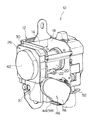
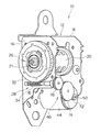
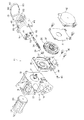
図1には、本発明の実施の形態に係るウエビング巻取装置10の全体構成が斜視図にて示されており、図2には、ウエビング巻取装置10の主要部分の構成が斜視図にて示されている。また、図3には、このウエビング巻取装置10の全体構成が分解斜視図にて示されている。
FIG. 1 is a perspective view showing the overall configuration of a webbing take-
ウエビング巻取装置10は、フレーム12を備えている。フレーム12は略板状の背板14と、この背板14の幅方向両端から一体に延出する一対の脚板16及び脚板18とによって構成されており、背板14がボルト等の図示しない締結手段によって車体に固定されることで車体に取り付けられる構成となっている。
The webbing take-
フレーム12の一対の脚板16と脚板18との間には、ダイカスト等によって製作された巻取軸20が回転可能に配置されている。巻取軸20は全体としては鼓形状をなしており、長尺帯状に形成されたウエビングベルト(図示省略)の基端部が連結固定されている。巻取軸20をその軸周り一方(以下、この方向を「巻取方向」と称する)へ回転させると、ウエビングベルトがその基端側から巻取軸20の外周部に層状に巻き取られ、一方、ウエビングベルトをその先端側から引っ張れば、これに伴い巻取軸20が回転しながらウエビングベルトが引き出される(以下、ウエビングベルトを引き出す際の巻取軸20の回転方向を「引出方向」と称する)。
Between the pair of leg plates 16 and the
巻取軸20の一端側は、脚板18を貫通してフレーム12の外部に突出している。脚板18の側方には、図示を省略したロック機構が配置されている。ロック機構は、加速度センサを含んで構成されており、脚板16と脚板18との間に掛け渡されたロックプレート22、及び巻取軸20の軸芯部分に設けられたトーションバー24に連係している。車両の急減速時等には、ロック機構の作動によりトーションバー24の一端がロックプレート22を介して拘束されてエネルギー吸収が行われつつ、巻取軸20の引出方向回転が阻止される構成となっている。
One end side of the winding
一方、巻取軸20の他端側には、連結スクリュー21が取付けられている。この連結スクリュー21は、脚板16を貫通してフレーム12の外方に突出しており、さらに、脚板16の外側には、クラッチ26及びクラッチギヤ部28が配置されている。
On the other hand, a connecting
クラッチ26及びクラッチギヤ部28は、ケース30内に共に収容された構成となっており、クラッチ26は連結スクリュー21に接続されている。また、クラッチ26は、クラッチギヤ部28を構成するギヤホイール32に連係している。このギヤホイール32は、外周縁にウォームホイール歯が形成された所謂ウォームホイールとされている。ギヤホイール32は、巻取軸20と同軸的に配置されており、このギヤホイール32がクラッチ26を介して連結スクリュー21(すなわち、巻取軸20)に機械的に接続されている。このため、ギヤホイール32が回転すると、クラッチ26を介して駆動力が伝達されて巻取軸20が巻取方向に回転されると共に、巻取軸20側で生じた回転の伝達を遮断して当該回転がギヤホイール32に伝達されることを防止する構成となっている。さらに、クラッチ26に接続された連結スクリュー21の先端は、このクラッチ26を貫通して側方へ延出している。
The clutch 26 and the
また、ケース30内には、クラッチギヤ部28を構成するウォームギヤ34が設けられている。ウォームギヤ34は、巻取軸20と直交する状態で自身の軸が配置され、その端部がブッシュ36、37を介してケース30に支持されると共に、ギヤホイール32に噛み合っており、さらに、その一端側はケース30から外方へ突出して設けられている。また、ウォームギヤ34の先端部を支持するケース30の軸受け部分には、鋼球38が収容されてウォームギヤ34の先端部に接触しており、さらに、アジャストスクリュー40が螺入している。アジャストスクリュー40は、その先端部で鋼球38を押圧することで鋼球38をウォームギヤ34の先端に圧接させている。これにより、ウォームギヤ34の軸方向の変位が規制されている(スラスト調整されている)。このウォームギヤ34が回転することで、ギヤホイール32が回転される構成となっている。
A
以上の構成のクラッチ26及びクラッチギヤ部28を収容するケース30は、カバークラッチ31によって被覆されている。
The
このように、クラッチ26とクラッチギヤ部28とは、単一のケース30に一体的に組み付けられており、全体としてユニット化された構成となっている。
As described above, the clutch 26 and the
クラッチ26及びクラッチギヤ部28(ケース30)の側方には、スプリング・コンプリート42が配置されている。スプリング・コンプリート42は、内部に渦巻きばね(図示省略)を収容している。この渦巻きばねは、渦巻き方向外側の端部がケース本体に係止されると共に、渦巻き方向内側の端部が、クラッチ26を貫通した連結スクリュー21の先端に係止されており、巻取軸20を巻取方向へ付勢している。
A spring complete 42 is disposed on the side of the clutch 26 and the clutch gear portion 28 (case 30). The spring complete 42 accommodates a spiral spring (not shown) inside. In the spiral spring, the end on the outer side in the spiral direction is locked to the case body, and the end on the inner side in the spiral direction is locked to the tip of the connecting
一方、巻取軸20の下方で脚板16と脚板18との間には、モータ44及びモータギヤ部46が配置されている。
On the other hand, a
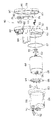
ここで、図4には、このモータ44及びモータギヤ部46の構成が分解斜視図にて示されている。
Here, in FIG. 4, the configurations of the
モータ44及びモータギヤ部46は、ハウジング48を備えている。このハウジング48の一側にモータ44が取り付けられると共に、ハウジング48の他側にモータギヤ部46が設けられている。モータ44は、その回転軸50の先端側(出力側)がハウジング48に向く状態でハウジング48の一側に固定されており、回転軸50先端(出力側)はハウジング48の他側(モータギヤ部46の側)に突出している。
The
また、モータ44の後端側には、ベースプレート54が取り付けられている。ベースプレート54にはモータ駆動用の電気ハーネス52が取り回されており、さらに、この電気ハーネス52は、モータ44の本体部分に設けられた給電端子56に圧着端子構造によって接続されている。
A base plate 54 is attached to the rear end side of the
更に、モータ44は、Oリング57を介在してカバーモータ58によって被覆されている。カバーモータ58には爪部60が設けられており、この爪部60がハウジング48に設けられた爪受け突起62に嵌合係止することでカバーモータ58がハウジング48に固定されている。
Further, the
またここで、カバーモータ58には第1凹部64が設けられており、この第1凹部64に対応してベースプレート54には第1凹部64内に嵌入可能な凸部66が設けられている。さらに、前記モータ44には、ベースプレート54の凸部66に対応して凸部66が嵌入可能な第2凹部68が設けられている。
Here, the
すなわち、凸部66を第2凹部68に嵌入させてモータ44をベースプレート54に対し位置決めすると共に、凸部66を第1凹部64に嵌入させてベースプレート54をカバーモータ58に位置決めし、しかも爪部60を爪受け突起62に嵌合係止させてカバーモータ58をハウジング48に取付け固定することにより、ハウジング48に対するモータ44の軸周りの組付け位置が一義的に特定される構成となっている。
That is, the
さらに、モータ駆動用の電気ハーネス52は、モータ44の出力側と反対のフレーム12の背板14へ向けて、カバーモータ58の後端部分から取り出されている。また、このカバーモータ58の電気ハーネス52の取出し部分は、ゴムキャップ70によって防水されている。
Further, the
一方、ハウジング48の他側(モータギヤ部46の側)に突出するモータ44の回転軸50の先端には、モータギヤ部46の複数の平歯ギヤを構成するピニオン72が取り付けられている。また、モータギヤ部46には、各々が外歯の平歯ギヤとされた駆動力伝達手段を構成するギヤ74及びギヤ76が互いに噛み合った状態で収容されている。これらのギヤ74、ギヤ76は、共に自身の軸がモータ44の回転軸50と平行な状態で配置されており、ギヤ74はピニオン72に噛み合っており、最終平歯ギヤとされるギヤ76は、前述したクラッチギヤ部28のケース30から外方へ突出するウォームギヤ34の一端部に、着脱可能に連結されている。このため、モータ44が駆動すると、ピニオン72、ギヤ74、及びギヤ76を介して駆動力が伝達されてウォームギヤ34が回転される構成である。
On the other hand, pinions 72 constituting a plurality of spur gears of the
また、これらのピニオン72、ギヤ74、及びギヤ76は、ハウジング48に取り付けられたカバーギヤ78によって被覆されている。カバーギヤ78には爪部80が設けられており、この爪部80がハウジング48に設けられた爪受け部82に嵌合係止することでカバーギヤ78がハウジング48に固定されている。
The
このように、モータ44とモータギヤ部46とは、何れも単一のハウジング48に一体的に組み付けられており、全体としてユニット化された構成となっている。
Thus, both the
以上の構成のモータ44及びモータギヤ部46は、ハウジング48に一体に設けられた取付ステー84が、クラッチ26及びクラッチギヤ部28を収容するケース30(すなわち、フレーム12)にスクリュウ86によって着脱可能に取り付けられている。このハウジング48のケース30(フレーム12)への取付装着状態においては、モータ44は、回転軸50が巻取軸20と直交しかつその出力側がフレーム12の背板14と反対側へ向く状態となっており、しかも、一対の脚板16と脚板18との間であって巻取軸20の直下に位置した構成となっている。
In the
またここで、前述の如き構成のモータ44及びモータギヤ部46は、モータギヤ部46の最終平歯ギヤとしてのギヤ76が、クラッチ26及びクラッチギヤ部28のウォームギヤ34に分離可能に連結されており、しかも、取付ステー84がケース30にスクリュウ86によって着脱可能に取り付けられているため、スクリュウ86を取り外して取付ステー84をケース30から取り外すことで、モータ44及びモータギヤ部46をアッセンブリ状態のままでケース30(フレーム12)から独立して分離することができるように構成されている。
Further, here, the
またさらに、上述したモータ44は、例えば、前方監視装置等の検出信号に基づいて作動される構成となっている。
Furthermore, the
次に本実施の形態の作用を説明する。 Next, the operation of this embodiment will be described.
上記構成のウエビング巻取装置10では、乗員が車両の座席に着席して、ウエビングベルトを身体に掛けまわし、例えば、ウエビングベルトに設けられたタングプレートをバックル装置に係合させることで、ウエビングベルトの乗員身体に対する装着状態となる。
In the webbing take-up
ここで、このウエビングベルト装着状態において、乗員の身体移動等に起因するウエビングベルトの巻取り・引出しが行われても、すなわち巻取軸20が巻取方向あるいは引出方向に回転しても、クラッチ26によって、この巻取軸20の回転力がモータ44の回転軸50に伝達されることはない。
Here, even when the webbing belt is wound and pulled out due to the movement of the occupant in the state where the webbing belt is worn, that is, even if the winding
一方、例えば、車両走行中に車両の前方に障害物が存在ししかも車両と障害物との間隔(車両から障害物までの距離)が所定範囲内に達すると、モータ44の駆動が開始され、回転軸50が急激に回転される。
On the other hand, for example, when an obstacle is present in front of the vehicle while the vehicle is running and the distance between the vehicle and the obstacle (the distance from the vehicle to the obstacle) reaches a predetermined range, the driving of the
このモータ44の回転軸50が回転されると、その回転力がモータギヤ部46のピニオン72、ギヤ74、及びギヤ76、並びに、クラッチギヤ部28のウォームギヤ34、及びギヤホイール32によってクラッチ26に伝達され、さらにクラッチ26を介して巻取軸20に回転力が伝達されて、巻取軸20がウエビング巻取方向に回転される。これにより、ウエビングベルトの緩み、所謂「スラック」が解消されて、ウエビングベルトによる乗員身体に対する拘束力が向上し、仮に、その後に乗員が車両急制動(急ブレーキ)の操作を行ない、車両が急減速状態になったとしてもウエビングベルトが確実に乗員の身体を保持する。
When the
また、このように、スラックが解消された状態でモータ44が停止すると、モータ44の回転軸50と巻取軸20との機械的な連結が解除される。
Further, when the
ここで、本実施の形態に係るウエビング巻取装置10では、巻取軸20を支持するためのフレーム12を構成する一対の脚板16、18のうち一方の脚板16の側方にクラッチ26が配置され、しかも、回転軸50が巻取軸20と直交する状態で脚板16と脚板18との間であって巻取軸20の直下にモータ44が配置された構成となっているため、フレーム12の外側にモータ44を配置する構造に比べて、本ウエビング巻取装置10を全体的に大幅にコンパクトにできる。すなわち、モータ44のような比較的大柄の部品を一対の脚板16と脚板18との間であって巻取軸20の直下に配置した構成であるため、当該大柄な部品であるモータ44がフレーム12(脚板16、18)から外方へ突出することがなく、一対の脚板16と脚板18の間のスペースを有効に利用することができ、装置を全体としてコンパクトにすることができる。またしかも、フレーム12の外側にモータ44を配置する構造に比べて、上記のようにモータ44を一対の脚板16、18の間であって巻取軸20の直下に配置した構成であるため、ウエビング巻取装置10の全体的な重量バランスを脚板16と脚板18の対向方向の中央側に寄せることができ、重量的にウエビング巻取装置10を安定させることができる。
Here, in the webbing take-up
また、本実施の形態に係るウエビング巻取装置10では、一方の脚板16の側方にクラッチ26を配置ししかも一対の脚板16、18の間であって巻取軸20の直下にモータ44を配置した構成であるため、モータ44とクラッチ26とを近接配置でき、しかも、モータ44の回転軸50の出力側がフレーム12の背板14と反対側へ向けて配置されているため、モータ44の回転軸50とクラッチ26とを連結するモータギヤ部46及びクラッチギヤ部28(駆動力伝達手段)を無理なく配置することができる。したがって、モータギヤ部46及びクラッチギヤ部28の構成を簡素化でき、この意味でも、装置をコンパクトにでき、更にはコストを安価にできる。
Further, in the webbing take-up
さらに、モータ44のような比較的重量のある部品を一対の脚板16、18の間であって巻取軸20の直下に配置した構成であるため、各脚板16、18及びこれらの脚板16、18を連結する背板14の何れか1つだけでなく、必要に応じては、一対の脚板16、18及び背板14の何れか2つ又は全てでモータ44を支持させることができる。これにより、モータ44を支持するための格別な強度の向上が不要になり、この結果、装置の軽量化とコストダウンを図ることが可能となる。
Further, since a relatively heavy component such as the
またさらに、本実施の形態に係るウエビング巻取装置10では、モータギヤ部46の最終平歯ギヤとしてのギヤ76とクラッチギヤ部28のウォームギヤ34とは、分離可能に連結されているため、モータギヤ部46をクラッチギヤ部28とは独立して分離・交換することが可能である。したがって、例えば、ピニオン72、ギヤ74、及びギヤ76等の複数の平歯ギヤの歯数やその個数等を変更した異なる別のモータギヤ部46に容易に交換・適用することができる。これにより、モータ44からクラッチ26へ伝達する駆動力の変速比(減速比)を容易に変更、設定でき、モータ44が駆動した際のクラッチ26に伝わる回転速度、ひいては巻取軸20の回転速度の設定・変更(ウエビング巻取り特性のバリエーションの設定)を容易に行うことが可能になる。
Furthermore, in the webbing take-up
また、モータギヤ部46をクラッチギヤ部28とは独立して分離・交換することが可能であるため、前述の如く変速比(減速比)の変更等のためにモータギヤ部46を交換・変更する場合であっても、モータギヤ部46の複数の平歯ギヤの噛合い状態、及び、クラッチギヤ部28のウォームギヤ34とギヤホイール32の噛合い状態は、何ら変化することがない(影響を受けない)。したがって、各歯(ギヤ)の噛合い精度が変化することが無く、駆動力の伝達効率が低下(悪化)することがない。
Further, since the
10 ウエビング巻取装置
12 フレーム
14 背板
16 脚板
18 脚板
20 巻取軸
26 クラッチ
28 クラッチギヤ部(駆動力伝達手段)
30 ケース
32 ギヤホイール
34 ウォームギヤ
44 モータ
46 モータギヤ部(駆動力伝達手段)
48 ハウジング
72 ピニオン
74 ギヤ
76 ギヤ
DESCRIPTION OF
30
48
Claims (3)
前記一対の脚板の対向方向に軸方向が沿った状態で前記一対の脚板の間に回転可能に支持され、乗員拘束用のウエビングベルトの基端部が係止されて軸周りの一方向への回転で前記ウエビングベルトを巻き取る巻取軸と、
回転軸が前記巻取軸と直交する状態で前記一対の脚板の間に配置されたモータと、
前記一対の脚板のうち何れか一方の脚板の側方に配置され、機械的に前記モータと前記巻取軸との間に介在し、前記モータの回転を前記巻取軸に伝達して前記巻取軸を回転させると共に、前記巻取軸側で生じた回転の伝達を遮断して当該回転が前記モータに伝達されることを防止するクラッチと、
前記モータと前記クラッチとを連結し、前記モータの回転力を前記クラッチに伝達する駆動力伝達手段と、
を備えたウエビング巻取装置。 A frame in which a pair of leg plates facing each other are connected by a back plate, and
Rotation is supported between the pair of leg plates in a state in which the axial direction is along the opposing direction of the pair of leg plates, and the base end portion of the webbing belt for restraining the passenger is locked to rotate in one direction around the axis A winding shaft for winding the webbing belt with,
A motor disposed between the pair of leg plates in a state where a rotation shaft is orthogonal to the winding shaft;
It is disposed on the side of one of the pair of leg plates, and is mechanically interposed between the motor and the take-up shaft, and transmits the rotation of the motor to the take-up shaft to make the winding. A clutch that rotates the take-up shaft, interrupts transmission of rotation generated on the take-up shaft side, and prevents the rotation from being transmitted to the motor;
Driving force transmission means for connecting the motor and the clutch, and transmitting the rotational force of the motor to the clutch;
A webbing take-up device comprising:
前記モータの回転軸と平行な状態で自身の軸が配置され前記モータの回転軸に連結された複数の平歯ギヤから成るモータギヤ部と、
前記モータの回転軸と平行な状態で自身の軸が配置され前記モータギヤ部の最終平歯ギヤに分離可能に連結されたウォームギヤと、前記巻取軸と同軸的に配置され前記ウォームギヤに噛み合い前記ウォームギヤの回転力を前記クラッチに伝達するウォームホイールとから成るクラッチギヤ部と、
によって構成されている、ことを特徴とする請求項1または請求項2記載のウエビング巻取装置。 The driving force transmission means is
A motor gear portion comprising a plurality of spur gears, the shaft of which is arranged in parallel with the rotation shaft of the motor and connected to the rotation shaft of the motor;
A worm gear having its own shaft arranged parallel to the motor rotation shaft and detachably connected to the final spur gear of the motor gear portion; and a worm gear coaxially arranged with the winding shaft and meshing with the worm gear A clutch gear portion comprising a worm wheel that transmits the rotational force of
The webbing take-up device according to claim 1 or 2, wherein
Priority Applications (11)
| Application Number | Priority Date | Filing Date | Title |
|---|---|---|---|
| JP2004114310A JP2005297675A (en) | 2004-04-08 | 2004-04-08 | Webbing take-up device |
| TW094106289A TW200540044A (en) | 2004-04-08 | 2005-03-02 | Webbing retractor |
| EP05720136A EP1733936B9 (en) | 2004-04-08 | 2005-03-07 | Webbing take-up device |
| AU2005230294A AU2005230294B2 (en) | 2004-04-08 | 2005-03-07 | Webbing take-up device |
| CA002563490A CA2563490A1 (en) | 2004-04-08 | 2005-03-07 | Webbing take-up device |
| KR1020067022861A KR20070012440A (en) | 2004-04-08 | 2005-03-07 | Webbing retractor |
| PCT/JP2005/003864 WO2005097560A1 (en) | 2004-04-08 | 2005-03-07 | Webbing take-up device |
| US11/547,782 US7735767B2 (en) | 2004-04-08 | 2005-03-07 | Webbing take-up device |
| CN 200520016331 CN2860951Y (en) | 2004-04-08 | 2005-04-08 | Webbing winding device |
| CNB2005100657156A CN100336686C (en) | 2004-04-08 | 2005-04-08 | Tape device |
| CNB200610146705XA CN100506612C (en) | 2004-04-08 | 2005-04-08 | Tape device |
Applications Claiming Priority (1)
| Application Number | Priority Date | Filing Date | Title |
|---|---|---|---|
| JP2004114310A JP2005297675A (en) | 2004-04-08 | 2004-04-08 | Webbing take-up device |
Publications (1)
| Publication Number | Publication Date |
|---|---|
| JP2005297675A true JP2005297675A (en) | 2005-10-27 |
Family
ID=35329761
Family Applications (1)
| Application Number | Title | Priority Date | Filing Date |
|---|---|---|---|
| JP2004114310A Pending JP2005297675A (en) | 2004-04-08 | 2004-04-08 | Webbing take-up device |
Country Status (2)
| Country | Link |
|---|---|
| JP (1) | JP2005297675A (en) |
| CN (2) | CN2860951Y (en) |
Cited By (2)
| Publication number | Priority date | Publication date | Assignee | Title |
|---|---|---|---|---|
| JP2014237355A (en) * | 2013-06-06 | 2014-12-18 | 株式会社東海理化電機製作所 | Seat belt device |
| CN110466474A (en) * | 2018-05-09 | 2019-11-19 | 奥托立夫开发公司 | Arrangement of clutch, seat belt retractor and safety belt assembly |
Families Citing this family (6)
| Publication number | Priority date | Publication date | Assignee | Title |
|---|---|---|---|---|
| KR100835938B1 (en) * | 2007-05-16 | 2008-06-09 | 델파이코리아 주식회사 | Cover structure of seat belt retractor |
| JP5319565B2 (en) * | 2010-01-21 | 2013-10-16 | 株式会社東海理化電機製作所 | Webbing take-up device |
| JP5450131B2 (en) * | 2010-01-29 | 2014-03-26 | タカタ株式会社 | Seat belt retractor and seat belt device provided with the same |
| EP2492159B1 (en) * | 2011-02-28 | 2013-12-25 | Volvo Car Corporation | Method and system for seat belt retraction speed control |
| DE102013205246B3 (en) * | 2013-03-25 | 2014-05-15 | Autoliv Development Ab | belt tensioner drive |
| CN106032137B (en) * | 2015-03-13 | 2018-10-16 | 比亚迪股份有限公司 | Webbing take-up device |
-
2004
- 2004-04-08 JP JP2004114310A patent/JP2005297675A/en active Pending
-
2005
- 2005-04-08 CN CN 200520016331 patent/CN2860951Y/en not_active Expired - Lifetime
- 2005-04-08 CN CNB200610146705XA patent/CN100506612C/en not_active Expired - Fee Related
Cited By (2)
| Publication number | Priority date | Publication date | Assignee | Title |
|---|---|---|---|---|
| JP2014237355A (en) * | 2013-06-06 | 2014-12-18 | 株式会社東海理化電機製作所 | Seat belt device |
| CN110466474A (en) * | 2018-05-09 | 2019-11-19 | 奥托立夫开发公司 | Arrangement of clutch, seat belt retractor and safety belt assembly |
Also Published As
| Publication number | Publication date |
|---|---|
| CN2860951Y (en) | 2007-01-24 |
| CN100506612C (en) | 2009-07-01 |
| CN1944120A (en) | 2007-04-11 |
Similar Documents
| Publication | Publication Date | Title |
|---|---|---|
| JP4571427B2 (en) | Webbing take-up device | |
| JP2008504160A (en) | Seat belt retractor with electric motor | |
| AU2005230294B2 (en) | Webbing take-up device | |
| JP2005297675A (en) | Webbing take-up device | |
| JP4272575B2 (en) | Webbing take-up device | |
| JP4571428B2 (en) | Webbing take-up device | |
| JP2006103405A (en) | Webbing take-up device | |
| JP4272574B2 (en) | Webbing take-up device | |
| JP4491266B2 (en) | Webbing take-up device | |
| JP4308734B2 (en) | Webbing take-up device | |
| JP5199311B2 (en) | Webbing take-up device | |
| TWI421180B (en) | Webbing retractor | |
| JP2010208638A (en) | Webbing winding device |
Legal Events
| Date | Code | Title | Description |
|---|---|---|---|
| A621 | Written request for application examination |
Free format text: JAPANESE INTERMEDIATE CODE: A621 Effective date: 20061020 |
|
| A131 | Notification of reasons for refusal |
Free format text: JAPANESE INTERMEDIATE CODE: A131 Effective date: 20090224 |
|
| A02 | Decision of refusal |
Free format text: JAPANESE INTERMEDIATE CODE: A02 Effective date: 20090707 |