JP2005297650A - Ball screw device and electric power steering device - Google Patents
Ball screw device and electric power steering device Download PDFInfo
- Publication number
- JP2005297650A JP2005297650A JP2004113627A JP2004113627A JP2005297650A JP 2005297650 A JP2005297650 A JP 2005297650A JP 2004113627 A JP2004113627 A JP 2004113627A JP 2004113627 A JP2004113627 A JP 2004113627A JP 2005297650 A JP2005297650 A JP 2005297650A
- Authority
- JP
- Japan
- Prior art keywords
- ball screw
- housing
- support member
- rack shaft
- bearing
- Prior art date
- Legal status (The legal status is an assumption and is not a legal conclusion. Google has not performed a legal analysis and makes no representation as to the accuracy of the status listed.)
- Withdrawn
Links
Images


Landscapes
- Transmission Devices (AREA)
- Power Steering Mechanism (AREA)
Abstract
【課題】 ボールネジ装置および電動パワーステアリング装置の装置内で発生する衝突音は、不快感をもたらしうるものであるため、抑止、低減されることが望ましい。
【解決手段】 本発明の電動パワーステアリング装置は、ラックシャフト22、転動ボール42およびボールネジナット40を支持する第2ベアリング38と、ハウジング24と、第2ベアリング38とハウジング24の間に設置されたゴム体46とを備える。また、ラックシャフト22を介してゴム体46と反対側には、第2ベアリング38をゴム体46に向かって押圧する押圧ボルト56が設けられている。押圧ボルトに押圧された第2ベアリング38はゴム体46に押し当てられるので、第2ベアリング38とハウジング24の間のガタは抑制され、衝突音は効果的に抑止される。
【選択図】 図2
PROBLEM TO BE SOLVED: To suppress and reduce a collision sound generated in a ball screw device and an electric power steering device because it can cause discomfort.
An electric power steering apparatus according to the present invention is installed between a second bearing that supports a rack shaft, a rolling ball, and a ball screw nut, a housing, and a second bearing and the housing. And a rubber body 46. A pressing bolt 56 that presses the second bearing 38 toward the rubber body 46 is provided on the opposite side of the rubber body 46 via the rack shaft 22. Since the second bearing 38 pressed by the pressing bolt is pressed against the rubber body 46, the play between the second bearing 38 and the housing 24 is suppressed, and the collision noise is effectively suppressed.
[Selection] Figure 2
Description
本発明は、電動モータ等の電動駆動源によってもたらされる力を利用して操舵機構に操舵補助力を付与する電動パワーステアリング装置に関する。 The present invention relates to an electric power steering device that applies a steering assist force to a steering mechanism by using a force provided by an electric drive source such as an electric motor.
電動パワーステアリング装置の一形態として、ラックシャフトが挿通されたボールネジナットを、ラックシャフトと同軸に設けられた電動モータによって回転させることにより、その回転出力をボールネジナットを介してラックシャフトの長手方向推力に変換するものが知られている。そのようにして得られたラックシャフトの長手方向推力は、操舵機構に伝達されて、車輪を操舵する際の補助力として用いられる。このようなタイプの電動パワーステアリング装置では、ラックシャフトとボールネジナットの間に形成された転動路に沿って多数のボールが転動自在に設けられている。ボールネジナットとボールの間には若干の隙間が形成されており、ボールを介してラックシャフトとボールネジナットの間に生じる摩擦力の軽減が図られている。 As one form of the electric power steering apparatus, a ball screw nut through which the rack shaft is inserted is rotated by an electric motor provided coaxially with the rack shaft, and the rotation output of the rack shaft is thrust through the ball screw nut in the longitudinal direction. What is known to convert to The longitudinal thrust of the rack shaft thus obtained is transmitted to the steering mechanism and used as an auxiliary force when steering the wheel. In this type of electric power steering device, a large number of balls are provided so as to roll along a rolling path formed between the rack shaft and the ball screw nut. A slight gap is formed between the ball screw nut and the ball to reduce the frictional force generated between the rack shaft and the ball screw nut via the ball.
実際の車両走行時には、路面の凹凸などによってもたらされた振動がタイヤやタイロッド等を経由してラックシャフトに伝わり加振される。この時、ボールネジナットとボールの間に形成された隙間のために、ボールとボールネジナットあるいはボールとラックシャフトが衝突音を発生させてしまうことがある。このような衝突音は、車両ドライバーに不快感をもたらしうるものであるため、抑止、除去されることが望ましい。 During actual vehicle travel, vibrations caused by road surface irregularities are transmitted to the rack shaft via the tires, tie rods, and the like, and are vibrated. At this time, because of the gap formed between the ball screw nut and the ball, the ball and the ball screw nut or the ball and the rack shaft may generate a collision sound. Since such a collision sound can cause discomfort to the vehicle driver, it is desirable to suppress and remove the collision sound.
このような衝突音を抑止、除去する手法として、従来から様々な方法が提案されている。例えば、ラックシャフトとボールスクリューナットの間に弾性材料のシールを挟んだり(特許文献1参照)、ボールスクリューナットとラックシャフトの間に径および弾性特性が異なるボールを設けたり(特許文献2参照)することによって、上述の衝突音を抑止、除去する手法が提案されている。
ラックシャフトやボールスクリューナットは、モータシャフト等の部材を介して、ベアリング等の支持部材によってハウジングに保持されている。このため、ベアリング等の支持部材のガタが大きいと、外部からの加振時にラックシャフトやボールスクリューナットが大きく振れてしまい、上述の衝突音が更に増大しうることとなる。従って、上述の衝突音を防ぐためには、外部からの加振時におけるラックシャフトやボールスクリューナットの振れを抑制することも大切である。 The rack shaft and the ball screw nut are held in the housing by a support member such as a bearing via a member such as a motor shaft. For this reason, if the backlash of the support member such as a bearing is large, the rack shaft and the ball screw nut are greatly shaken during external vibration, and the above-described collision noise can be further increased. Therefore, in order to prevent the above-described collision noise, it is also important to suppress the shake of the rack shaft and the ball screw nut during external vibration.
しかしながら、電動パワーステアリング装置を組み立てる際には、ベアリング等の支持部材をハウジングに収容させることがあり、そのようなハウジングの内径は支持部材の外径よりも若干大きくなるように加工されるのが一般的である。従って、パワーステアリング装置の組み立て後には、支持部材とハウジングとの間に所定の微少隙間が存在することがある。このような支持部材とハウジングの間に存在する隙間、あるいはラックシャフトとボールスクリューナットの間に存在する隙間などが原因で、外部からの衝撃や振動等が加えられるとラックシャフトやボールスクリューナットが振れてしまい、上述の衝突音が増大してしまうことがある。 However, when assembling the electric power steering apparatus, a support member such as a bearing may be accommodated in the housing, and the inner diameter of such a housing is processed to be slightly larger than the outer diameter of the support member. It is common. Therefore, a predetermined minute gap may exist between the support member and the housing after the power steering device is assembled. Due to such a gap existing between the support member and the housing, or a gap existing between the rack shaft and the ball screw nut, the rack shaft and the ball screw nut are subjected to an impact or vibration from the outside. It may shake and the above-mentioned collision sound may increase.
本発明は上述の事情を鑑みてなされたものであり、その目的は、衝突音を抑制、低減させることのできるボールネジ装置および電動パワーステアリング装置を提供することにある。 The present invention has been made in view of the above-described circumstances, and an object thereof is to provide a ball screw device and an electric power steering device capable of suppressing and reducing collision noise.
本発明のある態様はボールネジ装置に関する。このボールネジ装置は、ラックシャフトと、前記ラックシャフトにボールを介して連結され前記ラックシャフトを駆動するボールネジナットと、を含むボールネジ機構と、前記ボールネジ機構の外側に設けられ、支持部材を介して前記ボールネジ機構を保持するハウジングと、を備え、前記支持部材と前記ハウジングの間には弾性体が設けられている。当該ボールネジ装置によれば、弾性体によって支持部材とハウジングとの衝突が防がれ、支持部材とハウジングの間で生じうる衝突音を抑制、低減させることができる。 One embodiment of the present invention relates to a ball screw device. The ball screw device includes a ball screw mechanism including a rack shaft, a ball screw nut connected to the rack shaft via a ball and driving the rack shaft, and provided outside the ball screw mechanism. A housing for holding a ball screw mechanism, and an elastic body is provided between the support member and the housing. According to the ball screw device, the elastic member prevents the support member and the housing from colliding with each other, and the collision sound that may occur between the support member and the housing can be suppressed and reduced.
なお、ここでいう弾性体は、支持部材とハウジングの間に伝わってくる衝撃や振動等を効果的に減衰、抑制させることができる程度の弾性を示すものであればよく、例えばゴムなどのように弾性に富んだ材料で作られたものや、バネ構造などの弾性に富んだ構造を有するものを含みうる。 Here, the elastic body may be any elastic body that exhibits an elasticity that can effectively attenuate and suppress the shock and vibration transmitted between the support member and the housing, such as rubber. It is possible to include those made of an elastic material and those having an elastic structure such as a spring structure.
上述のボールネジ装置は、前記弾性体に対して前記支持部材を押圧する押圧手段を更に備えていてもよい。当該ボールネジ装置によれば、ボールネジ装置を組み立てる際の加工寸法のために支持部材とハウジングとの間に微少な隙間が生じるような場合であっても、組み立て等の後には支持部材が弾性体を介しハウジングに対して押圧されるので、支持部材とハウジングとの間の微少隙間をなくし又は小さくすることができ、衝突音を抑制、低減させることができる。 The above-described ball screw device may further include a pressing unit that presses the support member against the elastic body. According to the ball screw device, even if a minute gap is generated between the support member and the housing due to the processing dimensions when assembling the ball screw device, the support member does not move the elastic body after assembly. Therefore, the minute gap between the support member and the housing can be eliminated or reduced, and the collision noise can be suppressed or reduced.
前記押圧手段は、前記ボールネジ機構を介して前記弾性体と対向する位置に設けられていてもよい。例えば、ボールネジ機構を介し支持部材および弾性体と対向して配置された押圧手段によって、無理なく適切に支持部材を弾性体に押し当てることが可能である。「前記ボールネジ機構を介して前記弾性体と対向する位置」とは、ボールネジ機構を中心とした場合に弾性体と180度の角度を形成する位置の他に、ボールネジ機構を中心とした場合に弾性体と90度よりも大きな角度を形成する位置を含みうるものである。押圧手段は、ボールネジ機構を介して支持部材に圧力を加える位置に配置されて、支持部材が弾性体に対して押圧されるようにすることが可能である。 The pressing means may be provided at a position facing the elastic body via the ball screw mechanism. For example, the support member can be appropriately pressed against the elastic body without difficulty by pressing means arranged to face the support member and the elastic body via the ball screw mechanism. “Position facing the elastic body via the ball screw mechanism” means that the ball screw mechanism is elastic when centered on the ball screw mechanism, in addition to the position that forms an angle of 180 degrees with the elastic body. It may include a position that forms an angle greater than 90 degrees with the body. The pressing means can be arranged at a position where pressure is applied to the support member via the ball screw mechanism so that the support member is pressed against the elastic body.
前記弾性体は、前記ボールネジナットと前記ハウジングの間に設けられた前記支持部材と、前記ハウジングと、の間に設けられていてもよい。当該ボールネジ装置によれば、ボールネジナット−ハウジング間に設けられた支持部材とハウジングとの衝突が弾性体によって防がれ、ボールネジナットに設けられた支持部材とハウジングの間で生じうる衝突音を抑制、低減させることができる。 The elastic body may be provided between the support member provided between the ball screw nut and the housing, and the housing. According to the ball screw device, a collision between the support member provided between the ball screw nut and the housing and the housing is prevented by the elastic body, and a collision sound generated between the support member provided on the ball screw nut and the housing is suppressed. Can be reduced.
前記弾性体は、前記ラックシャフトと前記ハウジングの間に設けられた前記支持部材と、前記ハウジングと、の間に設けられていてもよい。当該ボールネジ装置によれば、ラックシャフト−ハウジング間に設けられた支持部材とハウジングとの衝突が弾性体によって防がれ、ラックシャフトに設けられた支持部材とハウジングの間で生じうる衝突音を抑制、低減させることができる。 The elastic body may be provided between the support member provided between the rack shaft and the housing and the housing. According to the ball screw device, a collision between the support member provided between the rack shaft and the housing and the housing is prevented by the elastic body, and a collision sound generated between the support member provided on the rack shaft and the housing is suppressed. Can be reduced.
前記弾性体は、前記ラックシャフトの軸方向において、前記支持部材よりも小さい幅をもって形成され、前記支持部材と前記ハウジングの間には、所定の大きさの空間が設けられていてもよい。当該ボールネジ装置によれば、支持部材とハウジングとの衝突が支持部材とハウジングとの間に積極的に設けられた所定の大きさの空間によって防がれ、支持部材とハウジングの間で生じうる衝突音を抑制、低減させることができる。 The elastic body may be formed with a width smaller than the support member in the axial direction of the rack shaft, and a space of a predetermined size may be provided between the support member and the housing. According to the ball screw device, the collision between the support member and the housing is prevented by the space of a predetermined size that is positively provided between the support member and the housing, and can occur between the support member and the housing. Sound can be suppressed and reduced.
なお、この空間は、通常走行時の振動によっては支持部材とハウジングとが衝突しない程度の大きさで形成される。 This space is formed in such a size that the support member and the housing do not collide with each other due to vibration during normal traveling.
本発明の別の態様は、電動駆動源によって操舵機構に操舵補助力を付与する電動パワーステアリング装置に関する。この電動パワーステアリング装置は、前記操舵機構に連結されるラックシャフトと、前記ラックシャフトにボールを介して連結され、前記電動駆動源によってもたらされる力を利用して前記ラックシャフトを駆動するボールネジナットと、を含むボールネジ機構と、前記ボールネジ機構の外側に設けられ、支持部材を介して前記ボールネジ機構を保持するハウジングと、を備え、前記支持部材と前記ハウジングの間には弾性体が設けられている。当該電動パワーステアリング装置によれば、弾性体によって支持部材とハウジングとの衝突が防がれ、支持部材とハウジングの間で生じうる衝突音を抑制、低減させることができる。ここでいう弾性体は、支持部材とハウジングの間に伝わってくる衝撃や振動等を効果的に減衰、抑制させることができる程度の弾性を示すものであればよく、例えばゴムなどのように材質的に弾性に富んだものや、バネ構造などのように構造的に弾性に富んだものを含みうる。 Another aspect of the present invention relates to an electric power steering apparatus that applies a steering assist force to a steering mechanism by an electric drive source. The electric power steering apparatus includes a rack shaft coupled to the steering mechanism, a ball screw nut coupled to the rack shaft via a ball, and driving the rack shaft using a force provided by the electric drive source; , And a housing provided outside the ball screw mechanism and holding the ball screw mechanism via a support member, and an elastic body is provided between the support member and the housing. . According to the electric power steering apparatus, the elastic member prevents the support member and the housing from colliding with each other, and the collision noise that may be generated between the support member and the housing can be suppressed and reduced. The elastic body here may be any material as long as it exhibits elasticity to such an extent that it can effectively attenuate and suppress shocks and vibrations transmitted between the support member and the housing, such as rubber. It may include a material that is highly elastic and a material that is structurally elastic such as a spring structure.
上述の電動パワーステアリング装置は、前記弾性体に対して前記支持部材を押圧する押圧手段を更に備えていてもよい。当該電動パワーステアリング装置によれば、パワーステアリング装置を組み立てる際の加工寸法のために支持部材とハウジングとの間に微少な隙間が生じるような場合であっても、組み立て等の後には支持部材が弾性体を介しハウジングに対して押圧されるので、支持部材とハウジングとの間の微少隙間をなくし又は小さくすることができ、衝突音を抑制、低減させることができる。 The above-described electric power steering apparatus may further include a pressing unit that presses the support member against the elastic body. According to the electric power steering device, even if a minute gap is generated between the support member and the housing due to the processing dimensions when the power steering device is assembled, the support member is not assembled after assembly. Since it presses with respect to a housing via an elastic body, the micro clearance gap between a supporting member and a housing can be eliminated or made small, and a collision sound can be suppressed and reduced.
前記押圧手段は、前記ボールネジ機構を介して前記弾性体と対向する位置に設けられていてもよい。例えば、ボールネジ機構を介し支持部材および弾性体と対向して配置された押圧手段によって、無理なく適切に支持部材を弾性体に押し当てることが可能である。「前記ボールネジ機構を介して前記弾性体と対向する位置」とは、ボールネジ機構を中心とした場合に弾性体と180度の角度を形成する位置の他に、ボールネジ機構を中心とした場合に弾性体と90度よりも大きな角度を形成する位置を含みうるものである。押圧手段は、ボールネジ機構を介して支持部材に圧力を加える位置に配置されて、支持部材が弾性体に対して押圧されるようにすることが可能である。 The pressing means may be provided at a position facing the elastic body via the ball screw mechanism. For example, the support member can be appropriately pressed against the elastic body without difficulty by pressing means arranged to face the support member and the elastic body via the ball screw mechanism. “Position facing the elastic body via the ball screw mechanism” means that the ball screw mechanism is elastic when centered on the ball screw mechanism, in addition to the position that forms an angle of 180 degrees with the elastic body. It may include a position that forms an angle greater than 90 degrees with the body. The pressing means can be arranged at a position where pressure is applied to the support member via the ball screw mechanism so that the support member is pressed against the elastic body.
前記弾性体は、前記ボールネジナットと前記ハウジングの間に設けられた前記支持部材と、前記ハウジングと、の間に設けられていてもよい。当該電動パワーステアリング装置によれば、ボールネジナット−ハウジング間に設けられた支持部材とハウジングとの衝突が弾性体によって防がれ、ボールネジナットに設けられた支持部材とハウジングの間で生じうる衝突音を抑制、低減させることができる。 The elastic body may be provided between the support member provided between the ball screw nut and the housing, and the housing. According to the electric power steering apparatus, collision between the support member provided between the ball screw nut and the housing and the housing is prevented by the elastic body, and a collision sound that can be generated between the support member provided on the ball screw nut and the housing. Can be suppressed and reduced.
前記弾性体は、前記ラックシャフトと前記ハウジングの間に設けられた前記支持部材と、前記ハウジングと、の間に設けられていてもよい。当該電動パワーステアリング装置によれば、ラックシャフト−ハウジング間に設けられた支持部材とハウジングとの衝突が弾性体によって防がれ、ラックシャフトに設けられた支持部材とハウジングの間で生じうる衝突音を抑制、低減させることができる。 The elastic body may be provided between the support member provided between the rack shaft and the housing and the housing. According to the electric power steering apparatus, a collision between the support member provided between the rack shaft and the housing and the housing is prevented by the elastic body, and a collision sound that can be generated between the support member provided on the rack shaft and the housing. Can be suppressed and reduced.
前記弾性体は、前記ラックシャフトの軸方向において、前記支持部材よりも小さい幅をもって形成され、前記支持部材と前記ハウジングの間には、所定の大きさの空間が設けられていてもよい。当該ボールネジ装置によれば、支持部材とハウジングとの衝突が支持部材とハウジングとの間に積極的に設けられた所定の大きさの空間によって防がれ、支持部材とハウジングの間で生じうる衝突音を抑制、低減させることができる。なお、この空間は、通常走行時の振動によっては支持部材とハウジングとが衝突しない程度の大きさで形成される。 The elastic body may be formed with a width smaller than the support member in the axial direction of the rack shaft, and a space of a predetermined size may be provided between the support member and the housing. According to the ball screw device, the collision between the support member and the housing is prevented by the space of a predetermined size that is positively provided between the support member and the housing, and can occur between the support member and the housing. Sound can be suppressed and reduced. This space is formed in such a size that the support member and the housing do not collide with each other due to vibration during normal traveling.
なお、上述した各要素を適宜組み合わせたものも、本件特許出願によって特許による保護を求める発明の範囲に含まれうる。 A combination of the above-described elements as appropriate can also be included in the scope of the invention for which patent protection is sought by this patent application.
本発明のボールネジ装置および電動パワーステアリング装置によれば、弾性体によって支持部材とハウジングとの衝突が防がれ、支持部材とハウジングの間で生じうる衝突音を抑制、低減させることが可能である。 According to the ball screw device and the electric power steering device of the present invention, the elastic member prevents the collision between the support member and the housing, and it is possible to suppress and reduce the collision noise that may occur between the support member and the housing. .
以下、図面を参照して本発明の各実施の形態について説明する。 Embodiments of the present invention will be described below with reference to the drawings.
(第1の実施の形態)
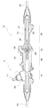
図1は、本実施の形態の電動パワーステアリング装置10の全体構成を示す図である。
(First embodiment)
FIG. 1 is a diagram illustrating an overall configuration of an electric
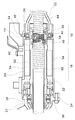
車両に搭載される本実施の形態の電動パワーステアリング装置10は、操舵機構12が接続される操舵機構接続部14と、電動駆動源であるモータを構成するモータ部16と、モータ部16によって生み出される回転力を利用して操舵機構12に操舵補助力を付与するボールネジ部18と、ラックシャフト22の一端部を形成するラック末端部20と、を有している。操舵機構接続部14とモータ部16とボールネジ部18とラック末端部20とは、図1に示すように、同軸上に順次設けられている。このような構成を有する電動パワーステアリング装置10では、軸状のラックシャフト22と、ラックシャフト22を取り囲むようにして設けられた円筒状のハウジング24とが、軸方向の略全長にわたって延在している。
The electric
操舵機構12は、操舵機構接続部14との接続位置に配設されたギアボックス26と、ギアボックス26内でラックシャフト22と噛み合うピニオン部(図示せず)を先端に有するピニオンシャフト28と、を有している。ピニオンシャフト28の端部のうちピニオン部とは反対側の端部には、図示しないユニバーサルジョイントを介してステアリングシャフトの一端が接続されており、ステアリングシャフトの他端にはステアリングホイールが設けられている。なお、ギアボックス26内には、ピニオンシャフト28に生じる操舵トルクを検出する図示しないトルクセンサが設けられている。
The
操舵機構接続部14の軸中心部分にはラックシャフト22の一部が配置されており、このラックシャフト22は、ギアボックス26内において操舵機構12のピニオンシャフト28に対し噛み合うようにして連結されている。
A part of the
ラック末端部20では、ラックシャフト22の一端部を取り囲むようにしてハウジング24が設けられており、ラックシャフト22とハウジング24の間には円筒状のエンドブッシュ30が設けられている。このエンドブッシュ30は、樹脂製であり、ラックシャフト22をハウジング24によって適切に保持させるための支持部材として機能する。
In the
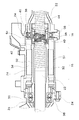
図2は、本実施の形態のモータ部16およびボールネジ部18の構成を示す拡大図である。
FIG. 2 is an enlarged view showing the configuration of the
モータ部16では、ブラシレスタイプのモータが形成されている。このモータは、ラックシャフト22を取り囲むようにして設けられた円筒状のモータシャフト32と、モータシャフト32を取り囲むようにして設けられたモータコイル部34と、を含んで構成されている。
In the
モータシャフト32は、磁性を帯びた材質を含んで構成されており、モータの回転子として機能する。本実施の形態のモータシャフト32は永久磁石が貼り付けられている。このモータシャフト32は、操舵機構接続部14に向かって延在するとともにボールネジ部18に向かっても延在しており、その両端部が第1ベアリング36および第2ベアリング38を介してハウジング24に保持されている。モータコイル部34は、複数のセグメントによって構成されるコイルを含んで構成されており、モータの固定子として機能する。
The
このような構成を有するモータは、操舵機構12に操舵補助力を付与する際の電動駆動源として機能し、外部から電力が供給されると、モータシャフト32は所定のトルクをもってラックシャフト22の周りで回転するようになっている。なお、モータは様々なタイプを採用することができ、例えば三相タイプのブラシレスモータや五相タイプのブラシレスモータなどを採用することも可能である。
The motor having such a configuration functions as an electric drive source for applying a steering assist force to the
ボールネジ部18は、ラックシャフト22の外側に設けられるとともにモータ部16のモータシャフト32の一端部に連結されたボールネジナット40と、ボールネジナット40とラックシャフト22の間に設けられた所定の大きさを有する複数の転動ボール42と、を有している。ボールネジ部18の軸中心部分に位置するラックシャフト22にはネジ溝状の転動路44が形成されており、この転動路44には複数の転動ボール42が転動自在に嵌め込まれている。このように、転動ボール42を介してラックシャフト22にボールネジナット40が連結されることによって、本実施の形態のボールネジ機構が構成されている。
The
このような構成を有するボールネジ部18においてボールネジナット40は、モータによってもたらされる力を利用してラックシャフト22を駆動する。具体的には、モータ部16のモータシャフト32が所定のトルクをもって回転すると、モータシャフト32に連結されたボールネジナット40にトルクが伝えられ、このトルクが転動路44を転動する複数の転動ボール42を介してラックシャフト22の軸方向の推力に変換され、ラックシャフト22は軸方向に駆動されることとなる。
In the
本実施の形態のボールネジ部18において、ボールネジナット40の外側にはモータ部16から延在するモータシャフト32が配置されており、このモータシャフト32の外側には第2ベアリング38およびゴム体46を介してハウジング24が配置されている。従って、ラックシャフト22、転動ボール42、およびボールネジナット40は、モータシャフト32、第2ベアリング38、およびゴム体46を介してハウジング24によって保持されている。
In the
第1ベアリング36および第2ベアリング38は、ラックシャフト22およびモータシャフト32を取り囲むようにして円筒状に設けられており、ラックシャフト22の内側に配置されているボールネジナット40等を含むボールネジ機構を、ハウジング24によって適切に保持させるための支持部材として機能する。
The
ゴム体46は、第2ベアリング38を取り囲む半円筒状に形成されており、ハウジング24の埋め込み部54に埋め込まれて取り付けられている。本実施の形態では、第2ベアリング38とハウジング24の間において、第2ベアリング38の上側半分のみが覆われるようにしてゴム体46が配設されている。このゴム体46は、ラックシャフト22の軸方向において、第2ベアリング38の大きさ以上の幅を有し、また、ラックシャフト22の軸方向と垂直な方向である半径方向において、所定の高さを有している。
The
ハウジング24の埋め込み部54は、ゴム体46に対応するようにしてハウジング24の内側が半径方向外向きに窪んだ状態で形成されており、ゴム体46が隙間なくフィットした状態で収容されるように形成されている。この埋め込み部54は、埋め込み部54に埋め込まれたゴム体46がハウジング24から第2ベアリング38に向かって僅かに突出するような深さを有している。この埋め込み部54は、収容されたゴム体46の軸方向の動きを制限している。
The embedded
第2ベアリング38の最下部には押圧ボルト56が押し当てられている。押圧ボルト56は、ラックシャフト22およびボールネジナット40を含むボールネジ機構を介し、第2ベアリング38およびゴム体46と対向する位置に配置されている。この押圧ボルト56は、ハウジング24を貫通して設けられており、押圧ボルト56の雄ねじ部とハウジング24に形成された雌ねじ部とが螺合した状態で、鉛直上方向にボールネジ機構を介して第2ベアリング38を押圧している。なお、押圧ボルト56による第2ベアリング38の押圧量は、押圧ボルト56とハウジング24との螺合状態を調整することによって調節可能となっている。
A
また図1に示すように、電動パワーステアリング装置10の両端部には、左右の操舵輪に接続されるタイロッド58が設けられている。各タイロッド58の先端部は、回動自在に連結された図示しないナックルアームおよびキングピンを介して操舵輪に取り付けられることとなる。
As shown in FIG. 1,
次に本実施の形態の作用について説明する。 Next, the operation of this embodiment will be described.
本実施の形態の電動パワーステアリング装置10のボールネジ部18では、第2ベアリング38が、押圧ボルト56によって押圧されてゴム体46に対し押し当てられることとなる。これにより、第2ベアリング38とゴム体46とハウジング24とはそれぞれ密着し、第2ベアリング38とハウジング24の間に隙間が生じてしまうことを効果的に防ぐことができる。このため、例えば電動パワーステアリング装置10の組み立て時に所定の微少隙間が第2ベアリング38とハウジング24の間に必要とされる場合であっても、組み立て後に押圧ボルト56の螺合状態を調整してゴム体46に対する第2ベアリング38の押圧力を調節することにより、第2ベアリング38、ゴム体46、およびハウジング24の相互間の微少隙間を抑制、縮小させることが可能である。
In the
また、上側方向に向かってモータシャフト32が押圧ボルト56によって押圧されることにより、モータシャフト32の内部の各構成部品も上側に押圧され偏心した状態となる。このため、モータシャフト32の内側に設けられているボールネジナット40、転動ボール42、およびラックシャフト22は、ゴム体46が設けられている上側に押圧されて、各々の間に存在していた隙間が抑制、縮小されることとなる。
Further, when the
このように、第2ベアリング38、モータシャフト32、ボールネジナット40、転動ボール42、およびラックシャフト22を、ゴム体46に向かって一方の方向に押圧ボルト56によって押圧することにより、第2ベアリング38とハウジング24の間の隙間の影響を解消することができるとともに、ボールネジナット40、転動ボール42、およびラックシャフト22の相互間の隙間の影響を解消することができる。これにより、電動パワーステアリング装置の組み立て時には、第2ベアリング38とハウジング24の間の隙間を確保して良好な組み付け性を実現する一方で、組み立て後には、第2ベアリング38とハウジング24の間のガタやボールネジナット40、転動ボール42、およびラックシャフト22の相互間のガタを抑制することが可能である。従って、組み付け性を犠牲にすることなく、上述のガタに起因する衝突音を効果的に抑止、低減させることができる。
In this way, the
特に、第2ベアリング38、モータシャフト32、ボールネジナット40、転動ボール42、およびラックシャフト22は弾性体であるゴム体46に向かって押圧されているので、外部から電動パワーステアリング装置10に伝わってきた衝撃や振動等はゴム体46によって緩和され、衝撃や振動等によってもたらされうる不都合は素早く解消されることとなる。
In particular, the
なお、ゴム体46の弾性係数は、電動パワーステアリング装置10の特性等が考慮されて決定されるものであり、外部から伝わってくる衝撃や振動等を効果的に緩和して、衝撃音の発生を有効に防ぐことができる程度の弾性係数であることが好ましい。
The elastic coefficient of the
次に本実施の形態の変形例について説明する。 Next, a modification of the present embodiment will be described.
ゴム体46は、第2ベアリング38の上側半分を取り囲むようにして配置された半円筒状のものには限定されない。ゴム体46は、第2ベアリング38とハウジング24の間において、第2ベアリング38の少なくとも一部を取り囲むようにして設けることが可能である。そして、ゴム体46は、押圧ボルト56によって押圧される第2ベアリング38が押し当てられるような位置に配置されていることが好ましい。従って、例えば第2ベアリング38の全周を取り囲むような円筒状にゴム体46を形成することも可能である。また、ゴム体46がいずれの位置に配置されたとしても、押圧ボルト56は、ボールネジ機構を介して第2ベアリング38およびゴム体46と対向する位置に配置することが可能である。
The
また、上述の第1の実施の形態では第2ベアリング38およびゴム体46が、ボールネジナット40の鉛直上下方向に設けられている場合について説明したが、第2ベアリング38およびゴム体46がボールネジナット40の近傍に設けられている場合にも上述と同様の作用効果を得ることができる。
Further, in the first embodiment described above, the case where the
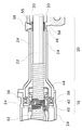
また、ハウジング24の埋め込み部54およびゴム体46を図3に示すように設けることも可能である。図3は、本実施の形態の一変形例におけるハウジング24とゴム体46と第2ベアリング38の構成を示す図である。本変形例のハウジング24の埋め込み部54は、ラックシャフト22の軸方向において第2ベアリング38の大きさ以上の幅をもって形成されているが、ゴム体46は、ラックシャフト22の軸方向において、第2ベアリング38よりも小さい幅をもって形成されている。このため、第2ベアリング38とハウジング24との間には所定の大きさの空間48が設けられている。この場合にも、第2ベアリング38、モータシャフト32、ボールネジナット40、転動ボール42、およびラックシャフト22は、押圧ボルト56によりゴム体46に向かって一方の方向に押圧されるので、第2ベアリング38とハウジング24の間のガタやボールネジナット40、転動ボール42、およびラックシャフト22の相互間のガタは解消され、そのようなガタに起因する衝突音が効果的に抑止、低減されることとなる。
Further, the embedded
(第2の実施の形態)
本実施の形態において、上述の第1の実施の形態と同一部分には同一符号を付して詳細な説明は省略する。
(Second Embodiment)
In the present embodiment, the same parts as those in the first embodiment are denoted by the same reference numerals, and detailed description thereof is omitted.
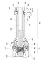
図4は、本実施の形態のボールネジ部18およびラック末端部20の構成を示す拡大図である。本実施の形態では、ゴム体46が、第2ベアリング38とハウジング24の間に設けられる代わりに、エンドブッシュ30とハウジング24の間に設けられている。また押圧ボルト56が、エンドブッシュ30を押圧するようにして設けられている。
FIG. 4 is an enlarged view showing the configuration of the
ゴム体46は、エンドブッシュ30を取り囲む半円筒状に形成されており、ハウジング24の埋め込み部54に埋め込まれて取り付けられている。本実施の形態では、エンドブッシュ30の下側半分のみが覆われるようにしてゴム体46が配設されている。このゴム体46は、ラックシャフト22の軸方向において、エンドブッシュ30の大きさ以上の幅を有し、また、ラックシャフト22の半径方向において、所定の高さを有している。なお、ゴム体46はエンドブッシュ30よりも弾性に富んだ材質を採用することが好ましい。
The
ハウジング24の埋め込み部54は、ゴム体46に対応しており、ゴム体46が隙間なくフィットした状態で埋め込まれるように形成されている。この埋め込み部54は、埋め込み部54に埋め込まれたゴム体46がハウジング24からエンドブッシュ30に向かって僅かに突出するような深さを有している。
The embedded
エンドブッシュ30の最上部には、中間部材55を介して押圧ボルト56が押し当てられている。この押圧ボルト56は、ハウジング24を貫通して設けられており、押圧ボルト56の雄ねじ部とハウジング24に形成された雌ねじ部とが螺合した状態で、鉛直下方向に向かってエンドブッシュ30を押圧している。なお中間部材55は、ワッシャーとしての役割も果たしうるものであり、押圧ボルト56によってエンドブッシュ30が適切に押圧されるような材質および構造を有している。
A
他の構成は、図1および図2に示す第1の実施の形態と略同一である。 Other configurations are substantially the same as those of the first embodiment shown in FIGS.
本実施の形態の電動パワーステアリング装置10も、第1の実施の形態と同様にして、衝撃音の発生が防がれている。
Similarly to the first embodiment, the electric
すなわち、電動パワーステアリング装置10のラック末端部20では、エンドブッシュ30が押圧ボルト56によりゴム体46に向かって一方の方向に押圧され、ゴム体46に対し押し当てられることとなる。これにより、エンドブッシュ30とゴム体46とハウジング24とはそれぞれ密着し、エンドブッシュ30とハウジング24の間に隙間が生じてしまうことを防ぐことができる。このため、電動パワーステアリング装置10の組み立て後に、押圧ボルト56の螺合状態を調整してゴム体46に対するエンドブッシュ30の押圧力を調節することにより、エンドブッシュ30とハウジング24の間の微少隙間を抑制、縮小させることができる。
That is, at the
また、エンドブッシュ30が押圧ボルト56によって下側方向に向かって押圧されることにより、エンドブッシュ30の内部のラックシャフト22も下側に押圧され偏心した状態となる。これにより、エンドブッシュ30とラックシャフト22の間の隙間を抑制、縮小させることが可能であるとともに、ボールネジ部18に延在するラックシャフト22、転動ボール42、およびボールネジナット40の相互間の隙間を抑制、縮小させることが可能である。
Further, when the
このように本実施の形態によれば、エンドブッシュ30とハウジング24の間のガタ、エンドブッシュ30とラックシャフト22の間のガタ、あるいはボールネジナット40、転動ボール42、およびラックシャフト22の相互間のガタによる影響を解消することができ、そのようなガタに起因する衝突音を効果的に抑止、低減させることができる。
As described above, according to the present embodiment, the play between the
次に本実施の形態の変形例について説明する。 Next, a modification of the present embodiment will be described.
ゴム体46は、エンドブッシュ30の下側半分を取り囲むようにして配置された半円筒状のものには限定されない。ゴム体46は、押圧ボルト56によって押圧されるエンドブッシュ30が押し当てられるような位置に配置されていることが好ましい。従って、例えばエンドブッシュ30の全周を取り囲むような円筒状にゴム体46を形成することも可能である。
The
また、ハウジング24の埋め込み部54およびゴム体46を図5に示すように設けることも可能である。図5は、本実施の形態の一変形例におけるハウジング24とゴム体46とエンドブッシュ30の構成を示す図である。本変形例のハウジング24の埋め込み部54は、ラックシャフト22の軸方向において、第2ベアリング38の大きさ以上の幅をもって形成されているが、ゴム体46は、ラックシャフト22の軸方向において、第2ベアリング38よりも小さい幅をもって形成されている。このためエンドブッシュ30とハウジング24の間には所定の大きさの空間50が設けられている。この場合にも、エンドブッシュ30およびラックシャフト22は押圧ボルト56によりゴム体46に向かって一定の方向に押圧されるので、エンドブッシュ30とハウジング24の間のガタ、エンドブッシュ30とラックシャフト22の間のガタ、あるいはボールネジナット40、転動ボール42、およびラックシャフト22の相互間のガタは解消され、そのようなガタに起因する衝突音が効果的に抑止、低減されることとなる。
Further, the embedded
(第3の実施の形態)
本実施の形態において、上述の第1の実施の形態と同一部分には同一符号を付して詳細な説明は省略する。
(Third embodiment)
In the present embodiment, the same parts as those in the first embodiment are denoted by the same reference numerals, and detailed description thereof is omitted.
図6は、本実施の形態のモータ部16およびボールネジ部18の構成を示す拡大図である。図7は、モータ部16の上側半分の詳細な構成を示す図である。
FIG. 6 is an enlarged view showing the configuration of the
本実施の形態では、ゴム体46が、第2ベアリング38の全周を取り囲む円筒状に形成されている。また、本実施の形態では押圧ボルトが設けられていない。
In the present embodiment, the
ゴム体46は、電動パワーステアリング装置10に衝撃や振動等が加えられていない状態で、第2ベアリング38とハウジング24とがゴム体46を介して連結された状態を維持するような大きさを有している。具体的には、ゴム体46は、ラックシャフト22の軸方向において、第2ベアリング38よりも小さい幅をもって形成されており、ラックシャフト22の半径方向において、比較的大きな高さを有しており、第2ベアリング38とハウジング24の間には所定の大きさの変動規定空間60が形成されている。
The
変動規定空間60の大きさは、第2ベアリング38、モータシャフト32、ボールネジナット40、転動ボール42、およびラックシャフト22の許容変動量を規定するものである。この変動規定空間60の大きさは、ゴム体46の特性、電動パワーステアリング装置10の特性、あるいは電動パワーステアリング装置10が搭載される車両の特性等に応じて決定される。具体的には、通常走行時の衝撃や振動等が電動パワーステアリング装置10に加えられた場合に、この衝撃や振動等はゴム体46によって緩和されることになるが、その緩和された衝撃や振動等によって第2ベアリング38とハウジング24とが衝突しないような大きさが考慮されて、変動規定空間60の大きさが決定されている。この時、第2ベアリング38、モータシャフト32、ボールネジナット40、転動ボール42、あるいはラックシャフト22等の電動パワーステアリング装置10の構成部品に不具合を生じさせないような変動範囲となるように、変動規定空間60の大きさが決定されることが好ましい。本実施の形態の変動規定空間60の大きさは、電動パワーステアリング装置10に衝撃や振動等が加えられていない状態で、ラックシャフト22の半径方向において、電動パワーステアリング装置10の組み立て時に必要とされる隙間よりも大きくなるように調整されている。
The size of the
なおゴム体46は、電動パワーステアリング装置10に加えられる衝撃や振動等を素早く減衰させることのできるような弾性を有することが好ましい。
The
他の構成は、図1および図2に示す第1の実施の形態と略同一である。 Other configurations are substantially the same as those of the first embodiment shown in FIGS.
本実施の形態の電動パワーステアリング装置10では、電動パワーステアリング装置10に加えられる衝撃や振動等をゴム体46によって緩和するとともに、変動規定空間60によって第2ベアリング38とハウジング24との衝突を防ぐことにより、衝撃音の発生が防がれている。
In the electric
電動パワーステアリング装置10に衝撃や振動等が加えられると、第2ベアリング38、モータシャフト32、ボールネジナット40、転動ボール42、あるいはラックシャフト22等の電動パワーステアリング装置10の構成部品は変動する。この時、この衝撃や振動等はゴム体46によって緩和されるので、第2ベアリング38等の変動が効果的に抑制される。
When an impact, vibration, or the like is applied to the electric
第2ベアリング38等が変動するような場合であっても、第2ベアリング38等の変動の大きさが変動規定空間60の範囲内であれば第2ベアリング38とハウジング24とは衝突しない。
Even when the
過大な衝撃や振動等が電動パワーステアリング装置10に加えられた場合には、変動規定空間60を区画するハウジング24の内壁部分がストッパーの役割を果たし、半径方向に関する第2ベアリング38等の変動が変動規定空間60の大きさよりも大きくなってしまうことを防いでいる。これにより、電動パワーステアリング装置10に不具合を生じうるほどに第2ベアリング38等が変動してしまうことを未然に防いでいる。
When excessive impact or vibration is applied to the electric
このように本実施の形態によれば、第2ベアリング38とハウジング24の間のガタがゴム体46によって解消される。また、電動パワーステアリング装置10に衝撃や振動等が加えられるような場合であっても、第2ベアリング38とハウジング24との衝突はゴム体46と変動規定空間60とによって防がれ、衝突音が発生してしまうことを効果的に抑止している。更に、本実施の形態のラックシャフト22、転動ボール42、およびボールネジナット40の相互間で発生する摩擦力は比較的小さいので、ボールネジ機構は動きを阻害されることなくスムーズに作動する。
As described above, according to the present embodiment, the backlash between the
なお、上述の第3の実施の形態では第2ベアリング38およびゴム体46が、ボールネジナット40の鉛直上下方向に設けられている場合について説明したが、第2ベアリング38、ゴム体46、および変動規定空間60がボールネジナット40の近傍に設けられている場合にも上述と同様の作用効果を得ることができる。
In the third embodiment described above, the case where the
本発明は、上述の各実施の形態および各変形例に限定されるものではなく、当業者の知識に基づいて各種の設計変更等の変形を加えることも可能であり、そのような変形が加えられた実施の形態も本発明の範囲に含まれうるものである。 The present invention is not limited to the above-described embodiments and modifications, and various modifications such as design changes can be added based on the knowledge of those skilled in the art. The described embodiments can also be included in the scope of the present invention.
例えば、ゴム体46の代わりに、ゴム以外の弾性に富む材質で作られた弾性体や、バネ型構造などのように優れた弾性を示す構造を有する弾性体を用いた場合にも、上述の各実施の形態あるいは各変形例と同様の作用効果を奏する。
For example, in the case where an elastic body made of a material rich in elasticity other than rubber or an elastic body having a structure exhibiting excellent elasticity such as a spring type structure is used instead of the
また、上述の各実施の形態および各変形例では、ラックシャフト22、転動ボール42、およびボールネジナット40を含むボールネジ機構が電動パワーステアリング装置10に応用されている場合について説明したが、上述のようなボールネジ機構を他の装置に応用する場合にも上述の各実施の形態あるいは各変形例と同様の作用効果を奏する。例えば、数値制御工作機械(NC工作機械)での位置決め、案内装置、運動用ネジ等に対しても、ボールネジ機構を含む本発明のボールネジ装置を適用することが可能である。
In each of the above-described embodiments and modifications, the case where the ball screw mechanism including the
10 電動パワーステアリング装置、 12 操舵機構、 14 操舵機構接続部、 16 モータ部、 18 ボールネジ部、 20 ラック末端部、 22 ラックシャフト、 24 ハウジング、 26 ギアボックス、 28 ピニオンシャフト、 30 エンドブッシュ、 32 モータシャフト、 34 モータコイル部、 36 第1ベアリング、 38 第2ベアリング、 40 ボールネジナット、 42 転動ボール、 44 転動路、 46 ゴム体、 54 埋め込み部、 56 押圧ボルト、 58 タイロッド、 60 変動規定空間
DESCRIPTION OF
Claims (12)
前記ボールネジ機構の外側に設けられ、支持部材を介して前記ボールネジ機構を保持するハウジングと、を備え、
前記支持部材と前記ハウジングの間には弾性体が設けられていることを特徴とするボールネジ装置。 A ball screw mechanism including a rack shaft, and a ball screw nut connected to the rack shaft via a ball and driving the rack shaft;
A housing that is provided outside the ball screw mechanism and holds the ball screw mechanism via a support member;
An elastic body is provided between the support member and the housing.
前記支持部材と前記ハウジングの間には、所定の大きさの空間が設けられている、
ことを特徴とする請求項1乃至5のいずれかに記載のボールネジ装置。 The elastic body is formed with a smaller width than the support member in the axial direction of the rack shaft,
A space of a predetermined size is provided between the support member and the housing.
The ball screw device according to any one of claims 1 to 5, wherein
前記操舵機構に連結されるラックシャフトと、前記ラックシャフトにボールを介して連結され、前記電動駆動源によってもたらされる力を利用して前記ラックシャフトを駆動するボールネジナットと、を含むボールネジ機構と、
前記ボールネジ機構の外側に設けられ、支持部材を介して前記ボールネジ機構を保持するハウジングと、を備え、
前記支持部材と前記ハウジングの間には弾性体が設けられていることを特徴とする電動パワーステアリング装置。 An electric power steering device that applies a steering assist force to a steering mechanism by an electric drive source,
A ball screw mechanism including a rack shaft coupled to the steering mechanism, and a ball screw nut coupled to the rack shaft via a ball and driving the rack shaft using a force provided by the electric drive source;
A housing that is provided outside the ball screw mechanism and holds the ball screw mechanism via a support member;
An electric power steering apparatus, wherein an elastic body is provided between the support member and the housing.
前記支持部材と前記ハウジングの間には、所定の大きさの空間が設けられている、
ことを特徴とする請求項7乃至11のいずれかに記載の電動パワーステアリング装置。 The elastic body is formed with a smaller width than the support member in the axial direction of the rack shaft,
A space of a predetermined size is provided between the support member and the housing.
The electric power steering apparatus according to any one of claims 7 to 11, wherein
Priority Applications (2)
| Application Number | Priority Date | Filing Date | Title |
|---|---|---|---|
| JP2004113627A JP2005297650A (en) | 2004-04-07 | 2004-04-07 | Ball screw device and electric power steering device |
| CNB2005100632695A CN100398374C (en) | 2004-04-07 | 2005-04-07 | Ball screw device and electric steering device |
Applications Claiming Priority (1)
| Application Number | Priority Date | Filing Date | Title |
|---|---|---|---|
| JP2004113627A JP2005297650A (en) | 2004-04-07 | 2004-04-07 | Ball screw device and electric power steering device |
Publications (1)
| Publication Number | Publication Date |
|---|---|
| JP2005297650A true JP2005297650A (en) | 2005-10-27 |
Family
ID=35067428
Family Applications (1)
| Application Number | Title | Priority Date | Filing Date |
|---|---|---|---|
| JP2004113627A Withdrawn JP2005297650A (en) | 2004-04-07 | 2004-04-07 | Ball screw device and electric power steering device |
Country Status (2)
| Country | Link |
|---|---|
| JP (1) | JP2005297650A (en) |
| CN (1) | CN100398374C (en) |
Cited By (1)
| Publication number | Priority date | Publication date | Assignee | Title |
|---|---|---|---|---|
| JP2007131087A (en) * | 2005-11-09 | 2007-05-31 | Kayaba Ind Co Ltd | Electric power steering device |
Families Citing this family (4)
| Publication number | Priority date | Publication date | Assignee | Title |
|---|---|---|---|---|
| JP5466185B2 (en) * | 2011-02-08 | 2014-04-09 | トヨタ自動車株式会社 | Vehicle rear wheel steering device |
| JP5656073B2 (en) * | 2011-02-16 | 2015-01-21 | 株式会社ジェイテクト | Vehicle steering apparatus and method for manufacturing vehicle steering apparatus |
| CN105151115A (en) * | 2015-08-18 | 2015-12-16 | 捷伸电子科技(上海)有限公司 | Electric power steering system |
| CN105313955A (en) * | 2015-11-17 | 2016-02-10 | 捷伸电子科技(上海)有限公司 | Electric power steering system |
Family Cites Families (4)
| Publication number | Priority date | Publication date | Assignee | Title |
|---|---|---|---|---|
| JP3799236B2 (en) * | 2001-01-22 | 2006-07-19 | 株式会社ジェイテクト | Electric power steering device |
| JP2000170866A (en) * | 1998-12-09 | 2000-06-23 | Toyota Motor Corp | Ball screw |
| JP2002249056A (en) * | 2001-02-21 | 2002-09-03 | Koyo Seiko Co Ltd | Electric power steering device |
| US6883635B2 (en) * | 2001-06-29 | 2005-04-26 | Delphi Technologies, Inc. | Ball-screw assembly isolator |
-
2004
- 2004-04-07 JP JP2004113627A patent/JP2005297650A/en not_active Withdrawn
-
2005
- 2005-04-07 CN CNB2005100632695A patent/CN100398374C/en not_active Expired - Fee Related
Cited By (1)
| Publication number | Priority date | Publication date | Assignee | Title |
|---|---|---|---|---|
| JP2007131087A (en) * | 2005-11-09 | 2007-05-31 | Kayaba Ind Co Ltd | Electric power steering device |
Also Published As
| Publication number | Publication date |
|---|---|
| CN100398374C (en) | 2008-07-02 |
| CN1680736A (en) | 2005-10-12 |
Similar Documents
| Publication | Publication Date | Title |
|---|---|---|
| JP5641195B2 (en) | Electric power steering device | |
| US10780912B2 (en) | Steering device | |
| JP2012091677A (en) | Vehicle steering device | |
| JP2012090496A (en) | Motor and electrically driven power steering device | |
| JP2005297650A (en) | Ball screw device and electric power steering device | |
| JP2010144825A (en) | Vehicular steering unit | |
| JP2008307911A (en) | Electric power steering device | |
| JP5016237B2 (en) | Electric motor and electric power steering device | |
| KR100695450B1 (en) | Electric power assist steering with worm gear clearance compensation | |
| JP2010143284A (en) | Electric power steering device | |
| CN118216068A (en) | Motor mounting structure, motor unit, and vehicle steering device | |
| JP6686373B2 (en) | Actuator | |
| JP5035669B2 (en) | Electric power steering device | |
| JP5439074B2 (en) | Ball screw with ball spline and manufacturing method thereof | |
| JP2003032955A (en) | Armature-supporting structure of motor | |
| JP4776345B2 (en) | Electric power steering device | |
| JP5233426B2 (en) | Ball spline | |
| KR100794938B1 (en) | Steering device with shock absorber for yoke spring | |
| JP2007106358A (en) | Power steering device | |
| JP2005214404A (en) | Screw mechanism and electromagnetic suspension using the same | |
| JP2014084079A (en) | Mount structure of electric power steering device | |
| JP2006224782A (en) | Electric steering device | |
| JP2004175243A (en) | Electric power steering device | |
| WO2019054095A1 (en) | Power steering device | |
| JP2021188700A (en) | Impact shock absorption device and steering device |
Legal Events
| Date | Code | Title | Description |
|---|---|---|---|
| A621 | Written request for application examination |
Free format text: JAPANESE INTERMEDIATE CODE: A621 Effective date: 20060719 |
|
| A761 | Written withdrawal of application |
Free format text: JAPANESE INTERMEDIATE CODE: A761 Effective date: 20071207 |