JP2005297627A - Wire harness wiring structure - Google Patents
Wire harness wiring structure Download PDFInfo
- Publication number
- JP2005297627A JP2005297627A JP2004112919A JP2004112919A JP2005297627A JP 2005297627 A JP2005297627 A JP 2005297627A JP 2004112919 A JP2004112919 A JP 2004112919A JP 2004112919 A JP2004112919 A JP 2004112919A JP 2005297627 A JP2005297627 A JP 2005297627A
- Authority
- JP
- Japan
- Prior art keywords
- wire harness
- groove
- space
- radiator
- radiator support
- Prior art date
- Legal status (The legal status is an assumption and is not a legal conclusion. Google has not performed a legal analysis and makes no representation as to the accuracy of the status listed.)
- Granted
Links
Images
Landscapes
- Details Of Indoor Wiring (AREA)
- Installation Of Indoor Wiring (AREA)
Abstract
Description
本発明は、自動車のエンジンルーム内でラジエータの上部を横断して配索されるワイヤーハーネスの配索構造に関するものである。 The present invention relates to a wiring structure for a wire harness that is routed across an upper portion of a radiator in an engine room of an automobile.
自動車のエンジンルームの前部には、エンジン冷却装置としてラジエータが設置されている。一方、自動車の前部には左右対称にヘッドランプ等が設置されており、これらヘッドランプ等に配線されるワイヤーハーネスは、最短の配線経路をとるため、通常はラジエータの上部を横断するように配索されている。例えば特許文献1には、ラジエータを保持するラジエータサポートの上部にワイヤーハーネスを樹脂に埋設した状態で配索する構造が開示されている。 A radiator is installed as an engine cooling device in the front part of the engine room of the automobile. On the other hand, headlamps etc. are installed symmetrically in the front part of the car, and the wire harness wired to these headlamps etc. usually takes the shortest wiring path, so it usually crosses the upper part of the radiator It has been routed. For example, Patent Document 1 discloses a structure in which a wire harness is embedded in a resin on an upper portion of a radiator support that holds a radiator.
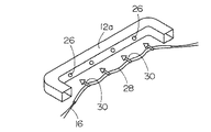
また図5に示すように、ラジエータの上部に設けられるラジエータサポートアッパー12aの側面に複数の係止穴26を形成しておき、ワイヤーハーネス16の保護チューブ28に取り付けた複数の係止部材30を、前記係止穴26に差し込むことで、ワイヤーハーネス16を配索する構造も実用化されている。この場合、ラジエータサポートアッパー12aの上部には通常、ラジエータ周りの見栄えをよくするため、ラジエータサポートカバーが設けられる。
Further, as shown in FIG. 5, a plurality of
しかしながら、特許文献1に開示された配索構造では、ワイヤーハーネスを樹脂に埋設したり、樹脂と一体に形成した係止突起をラジエータサポートアッパーに取り付けたりする必要があり、ワイヤーハーネスの製造及び組み付けが面倒である。また図5のような配索構造でも、ワイヤーハーネスを保護チューブで保護した上に、保護チューブに取り付けられた複数の係止部材をラジエータサポートアッパーに取り付ける必要があり、やはりワイヤーハーネスの組立、組み付けが面倒で、手間がかかる。 However, in the routing structure disclosed in Patent Document 1, it is necessary to embed the wire harness in the resin, or to attach the locking protrusion formed integrally with the resin to the radiator support upper. Is troublesome. In the wiring structure as shown in Fig. 5, it is necessary to protect the wire harness with the protective tube and attach a plurality of locking members attached to the protective tube to the radiator support upper. Is cumbersome and time consuming.
本発明の目的は、上記のような問題点に鑑み、ワイヤーハーネスに係止部材等を取り付けることなく、非常に簡単な作業でワイヤーハーネスを配索できるワイヤーハーネス配索構造を提供することにある。 In view of the above problems, an object of the present invention is to provide a wire harness routing structure in which a wire harness can be routed by a very simple operation without attaching a locking member or the like to the wire harness. .
本発明は、ラジエータサポートに保持されたラジエータの上部を横断して配索されるワイヤーハーネスの配索構造において、前記ラジエータサポートの上部を覆うラジエータサポートカバーにワイヤーハーネスを通す溝状空間を設け、この溝状空間にワイヤーハーネスを配索したことを特徴とするものである。 In the wiring structure of the wire harness that is routed across the upper portion of the radiator held by the radiator support, the present invention provides a groove-like space through which the wire harness passes through the radiator support cover that covers the upper portion of the radiator support. A wire harness is routed in the groove-like space.
また本発明のワイヤーハーネス配索構造は、前記溝状空間の両側の縁に相当する部分に係止部を設け、これらの係止部を前記溝状空間の両側の縁を狭めるようにして互いに係合させることにより、溝状空間に配索されたワイヤーハーネスを溝状空間の内壁で押圧固定した構成とすることが好ましい。 In the wire harness routing structure of the present invention, the engaging portions are provided at portions corresponding to the edges on both sides of the groove-like space, and these engaging portions are mutually connected so as to narrow the edges on both sides of the groove-like space. It is preferable that the wire harness arranged in the groove-like space is pressed and fixed by the inner wall of the groove-like space by being engaged.
また本発明のワイヤーハーネス配索構造は、ラジエータサポートの上部を覆うラジエータサポートカバーに複数のワイヤーハーネス支持片を設け、この支持片伝いにワイヤーハーネスを配索した構成とすることもできる。 Moreover, the wire harness wiring structure of this invention can also be set as the structure which provided the several wire harness support piece in the radiator support cover which covers the upper part of a radiator support, and wired the wire harness along this support piece.
本発明によれば、従来はラジエータ周りの見栄え、保護遮蔽の目的にしか使われていなかったラジエータサポートカバーを利用してワイヤーハーネスの配索空間を作り、そこにワイヤーハーネスを配索するだけでよいので、従来に比べ非常に簡単な作業でワイヤーハーネスを配索することができる。 According to the present invention, a wiring harness wiring space is created by using a radiator support cover that has been used only for the purpose of protecting and shielding the appearance around the radiator, and the wiring harness is simply routed there. Since it is good, it is possible to route the wire harness with a very simple operation compared to the conventional method.
特にラジエータサポートカバーの溝状空間に配索されたワイヤーハーネスを、溝状空間の内壁で押圧固定する構造にすれば、従来のような樹脂によるワイヤーハーネスの埋め込み、ワイヤーハーネスの保護チューブ通し、複数の係止部材による固定といった作業が必要なくなるので、ワイヤーハーネスの組立、配索、固定を非常に簡単に行うことができる。 In particular, if the wire harness routed in the groove-shaped space of the radiator support cover is pressed and fixed on the inner wall of the groove-shaped space, embedding of the wire harness with conventional resin, passing through the protective tube of the wire harness, multiple Since the work such as fixing with the locking member is not necessary, the assembly, wiring and fixing of the wire harness can be performed very easily.
またラジエータサポートカバーに支持片を設け、そこにワイヤーハーネスを支持させる構造でも、従来に比べ非常に簡単な作業でワイヤーハーネスを配索することができる。 Moreover, even if a support piece is provided on the radiator support cover and the wire harness is supported on the support piece, the wire harness can be routed by a very simple operation compared to the conventional case.
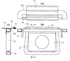
〔実施形態1〕 図1は本発明の一実施形態を示す。図において、10はラジエータ、12はラジエータ10を保持するラジエータサポート、12aはラジエータサポートアッパー、14はラジエータサポート12の上部を覆うラジエータサポートカバー、16はラジエータ10の上部を横断して配索されるワイヤーハーネスである。
Embodiment 1 FIG. 1 shows an embodiment of the present invention. In the figure, 10 is a radiator, 12 is a radiator support for holding the
このワイヤーハーネス配索構造の特徴は、ラジエータサポートカバー14にワイヤーハーネス16を通す溝状空間18を設け、この溝状空間18にワイヤーハーネス16を配索したことである。溝状空間18はラジエータサポートカバー14の一端側を折り返すことで簡単に形成することができる。ワイヤーハーネス16は、溝状空間18の内壁で押さえ付けて、移動しないようにすることが好ましい。
The feature of this wire harness routing structure is that a groove-
なお溝状空間18は、ラジエータサポートカバー14に溝状空間形成用の別部材を取り付けることで形成してもよい。
The groove-
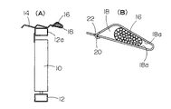
〔実施形態2〕 図2は本発明の他の実施形態を示す。このワイヤーハーネス配索構造では、ラジエータサポートカバー14に形成された溝状空間18の、一方の縁に相当する部分に適当な間隔で係止突起20を形成し、他方の縁に相当する部分に同じ間隔で係止穴22を形成してある。そして前記係止突起20を、溝状空間18の両側の縁を狭めるようにして係止穴22に係合させることにより、溝状空間18に配索されたワイヤーハーネス16を溝状空間の内壁18aで押圧固定したものである。このような構造にすると、ワイヤーハーネス16をより確実に固定することができる。上記以外の構成は実施形態1と同じであるので、同一部分には同一符号を付して説明を省略する。
Embodiment 2 FIG. 2 shows another embodiment of the present invention. In this wire harness routing structure, the
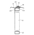
〔実施形態3〕 図3は本発明のさらに他の実施形態を示す。このワイヤーハーネス配索構造では、ラジエータサポートカバー14の幅方向中間部を折り曲げることによって溝状空間18を形成し、この溝状空間18の、一方の縁に相当する部分に係止突起20を形成し、他方の縁に相当する部分に係止穴22を形成してある。そして前記溝状空間18にワイヤーハーネス16を配索し、前記係止突起20を、溝状空間18の両側の縁を狭めるようにして係止穴22に係合させることにより、溝状空間18に配索されたワイヤーハーネス16を溝状空間の内壁で押圧固定したものである。このような構造でも実施形態2と同様な効果を得ることができる。上記以外の構成は実施形態1と同じであるので、同一部分には同一符号を付して説明を省略する。
Embodiment 3 FIG. 3 shows still another embodiment of the present invention. In this wire harness wiring structure, a groove-
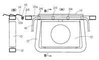
〔実施形態4〕 図4は本発明のさらに他の実施形態を示す。このワイヤーハーネス配索構造は、ラジエータサポートカバー14の一端側に複数のワイヤーハーネス支持片24を設け、この支持片24伝いにワイヤーハーネス16を配索したものである。この場合も、支持片24によってワイヤーハーネス16を押さえ付け、ワイヤーハーネス16が移動しないようにすることが好ましい。上記以外の構成は実施形態1と同じであるので、同一部分には同一符号を付して説明を省略する。
Embodiment 4 FIG. 4 shows still another embodiment of the present invention. In this wire harness routing structure, a plurality of wire
10:ラジエータ
12:ラジエータサポート
12a:ラジエータサポートアッパー
14:ラジエータサポートカバー
16:ワイヤーハーネス
18:溝状空間
20:係止突起
22:係止穴
24:ワイヤーハーネス支持片
10: Radiator 12:
Claims (3)
In the wiring structure of the wire harness that is routed across the upper part of the radiator held by the radiator support, a plurality of wire harness support pieces are provided on the radiator support cover that covers the upper part of the radiator support. A wiring harness wiring structure characterized by wiring a wiring harness.
Priority Applications (1)
| Application Number | Priority Date | Filing Date | Title |
|---|---|---|---|
| JP2004112919A JP4494846B2 (en) | 2004-04-07 | 2004-04-07 | Wire harness wiring structure |
Applications Claiming Priority (1)
| Application Number | Priority Date | Filing Date | Title |
|---|---|---|---|
| JP2004112919A JP4494846B2 (en) | 2004-04-07 | 2004-04-07 | Wire harness wiring structure |
Publications (2)
| Publication Number | Publication Date |
|---|---|
| JP2005297627A true JP2005297627A (en) | 2005-10-27 |
| JP4494846B2 JP4494846B2 (en) | 2010-06-30 |
Family
ID=35329721
Family Applications (1)
| Application Number | Title | Priority Date | Filing Date |
|---|---|---|---|
| JP2004112919A Expired - Fee Related JP4494846B2 (en) | 2004-04-07 | 2004-04-07 | Wire harness wiring structure |
Country Status (1)
| Country | Link |
|---|---|
| JP (1) | JP4494846B2 (en) |
Cited By (3)
| Publication number | Priority date | Publication date | Assignee | Title |
|---|---|---|---|---|
| JP2008213569A (en) * | 2007-03-01 | 2008-09-18 | Mazda Motor Corp | Automotive front structure |
| CN109050439A (en) * | 2018-07-18 | 2018-12-21 | 浙江创格科技有限公司 | A kind of engine wiring harness assembly bracket |
| JP7101135B2 (en) | 2019-03-13 | 2022-07-14 | 豊田鉄工株式会社 | Wire harness wiring structure |
Citations (8)
| Publication number | Priority date | Publication date | Assignee | Title |
|---|---|---|---|---|
| JPS62165124U (en) * | 1986-04-10 | 1987-10-20 | ||
| JPH0550842A (en) * | 1991-08-14 | 1993-03-02 | Nissan Motor Co Ltd | Body mounting structure for air conditioning capacitors |
| JPH05221275A (en) * | 1992-02-14 | 1993-08-31 | Suzuki Motor Corp | Mounting structure of wire harness for automobile |
| JPH08205356A (en) * | 1995-01-31 | 1996-08-09 | Kansei Corp | Structure of installing wiring harness |
| JPH10160047A (en) * | 1996-12-03 | 1998-06-16 | Yazaki Corp | Clamp member |
| JP2000324663A (en) * | 1999-04-30 | 2000-11-24 | Sumitomo Wiring Syst Ltd | Fitting structure of wire harness |
| JP2002176716A (en) * | 2000-12-11 | 2002-06-21 | Yazaki Corp | Harness protector |
| JP2003237630A (en) * | 2002-02-12 | 2003-08-27 | Calsonic Kansei Corp | Radiator core support member of automobile |
-
2004
- 2004-04-07 JP JP2004112919A patent/JP4494846B2/en not_active Expired - Fee Related
Patent Citations (8)
| Publication number | Priority date | Publication date | Assignee | Title |
|---|---|---|---|---|
| JPS62165124U (en) * | 1986-04-10 | 1987-10-20 | ||
| JPH0550842A (en) * | 1991-08-14 | 1993-03-02 | Nissan Motor Co Ltd | Body mounting structure for air conditioning capacitors |
| JPH05221275A (en) * | 1992-02-14 | 1993-08-31 | Suzuki Motor Corp | Mounting structure of wire harness for automobile |
| JPH08205356A (en) * | 1995-01-31 | 1996-08-09 | Kansei Corp | Structure of installing wiring harness |
| JPH10160047A (en) * | 1996-12-03 | 1998-06-16 | Yazaki Corp | Clamp member |
| JP2000324663A (en) * | 1999-04-30 | 2000-11-24 | Sumitomo Wiring Syst Ltd | Fitting structure of wire harness |
| JP2002176716A (en) * | 2000-12-11 | 2002-06-21 | Yazaki Corp | Harness protector |
| JP2003237630A (en) * | 2002-02-12 | 2003-08-27 | Calsonic Kansei Corp | Radiator core support member of automobile |
Cited By (3)
| Publication number | Priority date | Publication date | Assignee | Title |
|---|---|---|---|---|
| JP2008213569A (en) * | 2007-03-01 | 2008-09-18 | Mazda Motor Corp | Automotive front structure |
| CN109050439A (en) * | 2018-07-18 | 2018-12-21 | 浙江创格科技有限公司 | A kind of engine wiring harness assembly bracket |
| JP7101135B2 (en) | 2019-03-13 | 2022-07-14 | 豊田鉄工株式会社 | Wire harness wiring structure |
Also Published As
| Publication number | Publication date |
|---|---|
| JP4494846B2 (en) | 2010-06-30 |
Similar Documents
| Publication | Publication Date | Title |
|---|---|---|
| JP4689986B2 (en) | Band clamp | |
| JP6613146B2 (en) | Wire fixing structure | |
| JP2005297627A (en) | Wire harness wiring structure | |
| JP6670027B2 (en) | Harness holding structure | |
| JP5215163B2 (en) | Electrical junction box and electric wire routing method for electrical junction box | |
| JPH08140245A (en) | Grommet harness fixing structure | |
| JP2008104304A (en) | On-vehicle electric connection box | |
| JP6206119B2 (en) | Protective structure for vehicle horn wire harness and vehicle front grill module | |
| JP5910581B2 (en) | Cable tie mounting structure | |
| JP5896622B2 (en) | Wire fixing structure | |
| JP5569870B2 (en) | Bracket structure | |
| JP2001359217A (en) | Wire harness protector | |
| JP5979036B2 (en) | Wire harness wiring device for slide sheet | |
| JP4183078B2 (en) | Protector | |
| JP4680740B2 (en) | Wiring harness wiring structure | |
| KR200247511Y1 (en) | Bracket for wire harness grommet | |
| JP2006266089A (en) | Piping structure of radiator core support | |
| JP7329389B2 (en) | Connector block and wire routing structure | |
| JP2605704Y2 (en) | Clamp mounting structure | |
| JP2003116213A (en) | Cable protection member and main body of cable protection member | |
| KR20030016593A (en) | Antenna fixing apparatus of car | |
| JP4071566B2 (en) | Instrument panel structure for vehicles | |
| JP2017158284A (en) | Wire protection member and wiring harness | |
| JP2015056932A (en) | Protector for wiring harness | |
| JP2018059610A (en) | Clip for locking of wire harness |
Legal Events
| Date | Code | Title | Description |
|---|---|---|---|
| A621 | Written request for application examination |
Free format text: JAPANESE INTERMEDIATE CODE: A621 Effective date: 20060703 |
|
| A131 | Notification of reasons for refusal |
Free format text: JAPANESE INTERMEDIATE CODE: A131 Effective date: 20080929 |
|
| A977 | Report on retrieval |
Free format text: JAPANESE INTERMEDIATE CODE: A971007 Effective date: 20080930 |
|
| A521 | Written amendment |
Free format text: JAPANESE INTERMEDIATE CODE: A523 Effective date: 20081121 |
|
| A131 | Notification of reasons for refusal |
Free format text: JAPANESE INTERMEDIATE CODE: A131 Effective date: 20090323 |
|
| A521 | Written amendment |
Free format text: JAPANESE INTERMEDIATE CODE: A523 Effective date: 20090518 |
|
| A02 | Decision of refusal |
Free format text: JAPANESE INTERMEDIATE CODE: A02 Effective date: 20090914 |
|
| A521 | Written amendment |
Free format text: JAPANESE INTERMEDIATE CODE: A523 Effective date: 20091211 |
|
| A911 | Transfer of reconsideration by examiner before appeal (zenchi) |
Free format text: JAPANESE INTERMEDIATE CODE: A911 Effective date: 20100218 |
|
| TRDD | Decision of grant or rejection written | ||
| A01 | Written decision to grant a patent or to grant a registration (utility model) |
Free format text: JAPANESE INTERMEDIATE CODE: A01 Effective date: 20100319 |
|
| A01 | Written decision to grant a patent or to grant a registration (utility model) |
Free format text: JAPANESE INTERMEDIATE CODE: A01 |
|
| A61 | First payment of annual fees (during grant procedure) |
Free format text: JAPANESE INTERMEDIATE CODE: A61 Effective date: 20100408 |
|
| FPAY | Renewal fee payment (event date is renewal date of database) |
Free format text: PAYMENT UNTIL: 20130416 Year of fee payment: 3 |
|
| FPAY | Renewal fee payment (event date is renewal date of database) |
Free format text: PAYMENT UNTIL: 20130416 Year of fee payment: 3 |
|
| FPAY | Renewal fee payment (event date is renewal date of database) |
Free format text: PAYMENT UNTIL: 20140416 Year of fee payment: 4 |
|
| R250 | Receipt of annual fees |
Free format text: JAPANESE INTERMEDIATE CODE: R250 |
|
| R250 | Receipt of annual fees |
Free format text: JAPANESE INTERMEDIATE CODE: R250 |
|
| R250 | Receipt of annual fees |
Free format text: JAPANESE INTERMEDIATE CODE: R250 |
|
| LAPS | Cancellation because of no payment of annual fees |