JP2009248676A - Wire harness routing structure in vehicular seat - Google Patents
Wire harness routing structure in vehicular seat Download PDFInfo
- Publication number
- JP2009248676A JP2009248676A JP2008097216A JP2008097216A JP2009248676A JP 2009248676 A JP2009248676 A JP 2009248676A JP 2008097216 A JP2008097216 A JP 2008097216A JP 2008097216 A JP2008097216 A JP 2008097216A JP 2009248676 A JP2009248676 A JP 2009248676A
- Authority
- JP
- Japan
- Prior art keywords
- wire harness
- side frame
- vehicle seat
- seat
- harness
- Prior art date
- Legal status (The legal status is an assumption and is not a legal conclusion. Google has not performed a legal analysis and makes no representation as to the accuracy of the status listed.)
- Granted
Links
Images


Abstract
Description
本発明は、車両シートにおけるワイヤハーネス配索構造に関し、特に、配索作業性を向上させると同時に、車両シート下部のサイドフレームとの噛み込み等によってワイヤハーネスが損傷することを防止して、ワイヤハーネスの耐久性を向上させるための改良に関する。 The present invention relates to a wiring harness wiring structure in a vehicle seat, and in particular, improves wiring workability and at the same time prevents damage to the wiring harness due to biting with a side frame below the vehicle seat, and the like. The present invention relates to an improvement for improving the durability of a harness.
車両シートには、搭乗者の姿勢に合わせてシートクッションを前後方向及び上下方向に位置調整したり、シートバックをリクライニング動作させたりする電動シート装置や、エアバックを搭乗者とサイドドアとの間に展開させるエアバックユニット装置が設けられているものがあり、このような装置が搭載される車両シートにおいては、電動部品への給電のために、ワイヤハーネスが配索される。 The vehicle seat has an electric seat device that adjusts the position of the seat cushion in the longitudinal and vertical directions according to the posture of the passenger, and the reclining operation of the seat back, and an airbag between the passenger and the side door. There are some which are provided with an airbag unit device to be deployed, and in a vehicle seat on which such a device is mounted, a wire harness is routed for supplying power to the electric component.
図4はワイヤハーネスが配索される車両シート101の従来例を示したものであり、図5は図4に示した車両シート101の下部のサイドフレーム103からシート内部に導入されるワイヤハーネス105の配索構造の拡大図である。
FIG. 4 shows a conventional example of a
ワイヤハーネス105は、図5に示すように、シート外部からシート下部のサイドフレーム103に貫通形成されたハーネス挿通孔104を挿通させてシート内部に導入され、サイドフレーム103の上に車両前後方向に移動可能に装着されるシートクッション107や、シートバック109に組み込まれている電動部品まで配索される。
この種のワイヤハーネスの配索構造は、下記特許文献1にも開示されている。
As shown in FIG. 5, the
This type of wiring harness wiring structure is also disclosed in Patent Document 1 below.
ところが、図5に示したように、サイドフレーム103に貫通形成されたハーネス挿通孔104から車両シート101内にワイヤハーネス105を導入する従来の配索構造では、ワイヤハーネスをハーネス挿通孔104に挿通する作業に手間がかかり、配索作業性が悪いという問題が生じていた。
However, as shown in FIG. 5, in the conventional routing structure in which the
また、車両シート101のシートクッション107は、着座位置の調整のために、車両の前後方向にスライド可能に構成されているものが多く、シートクッション107をスライドさせた時に、シートクッション107に固定されているワイヤハーネスが引っ張られたり、あるいは振られたりして、ハーネス挿通孔104の縁に擦れたり、あるいはサイドフレーム103とシートクッション107との間に噛み込まれたりして、ハーネスを破損するおそれがあった。
Further, the
また、従来の車両シートにおけるワイヤハーネス配索構造では、ワイヤハーネス105は結束した束状態のままハーネス挿通孔104に挿通させている。このように結束した状態のワイヤハーネス105は、太い束になると曲げ難く、シートクッション107をスライド移動させる際に、ワイヤハーネスを曲げるために大きな操作力が必要になったり、あるいは、ワイヤハーネスを無理に曲げるために、ワイヤハーネスが痛みやすいという問題が生じた。
Moreover, in the conventional wire harness wiring structure in the vehicle seat, the
本発明の目的は上記課題を解消することに係り、ワイヤハーネスを車両シート下部のサイドフレームからシート内部に導入する際の配索作業性を向上させることができ、また、前記サイドフレームとの噛み込み等によってワイヤハーネスが損傷することを防止して、ワイヤハーネスの耐久性を向上させることのできる車両シートにおけるワイヤハーネス配索構造を提供することにある。 An object of the present invention is to solve the above-described problems, and can improve the routing workability when a wire harness is introduced from the side frame under the vehicle seat into the seat, and is engaged with the side frame. An object of the present invention is to provide a wire harness routing structure in a vehicle seat that can prevent the wire harness from being damaged due to the insertion of the wire harness and improve the durability of the wire harness.
本発明の上記目的は、下記構成により達成される。
(1) サイドフレームと、該サイドフレームの上に装着されるクッションパンと、を有する車両シートと、
前記サイドフレームから前記車両シート内に導入されて前記車両シート内部の各部に配索されるワイヤハーネスと、
を備えた、車両におけるワイヤハーネス配索構造であって、
前記ワイヤハーネスは、前記サイドフレームの上縁を跨いで、前記車両シート外部から前記車両シート内部に導入され、
前記サイドフレームの前記ワイヤハーネスが跨ぐ部位には、前記ワイヤハーネスが直接前記サイドフレームに接触することを防止する保護プロテクタが装備されると共に、該保護プロテクタは前記クッションパン及び前記サイドフレームの少なくとも一方に係合されたことを特徴とする車両シートにおけるワイヤハーネス配索構造。
The above object of the present invention is achieved by the following configurations.
(1) a vehicle seat having a side frame and a cushion pan mounted on the side frame;
A wire harness introduced from the side frame into the vehicle seat and routed to each part inside the vehicle seat;
A wiring harness wiring structure in a vehicle, comprising:
The wire harness is introduced into the vehicle seat from outside the vehicle seat, straddling the upper edge of the side frame,
A protective protector for preventing the wire harness from coming into direct contact with the side frame is provided at a portion of the side frame where the wire harness is straddled, and the protective protector is at least one of the cushion pan and the side frame. The wire harness wiring structure in the vehicle seat characterized by being engaged with the vehicle seat.
(2) 前記保護プロテクタには前記サイドフレームに係合するフレーム係合部と、前記クッションパンに係合するパン係合部とが設けられ、前記保護プロテクタを介して前記サイドフレームと前記クッションパンとが連結状態にされていることを特徴とする前記(1)に記載の車両シートにおけるワイヤハーネス配索構造。 (2) The protective protector is provided with a frame engaging portion that engages with the side frame and a pan engaging portion that engages with the cushion pan, and the side frame and the cushion pan are interposed via the protective protector. The wire harness wiring structure in the vehicle seat according to (1), wherein
上記(1)の構成によれば、ワイヤハーネスをシート外部から車両シート内に導入する際、又は車両シート内からワイヤハーネスをシート外部に引き出す際には、ワイヤハーネスを車両シート下部のサイドフレームの上縁を跨がせるため、サイドフレームに形成されたハーネス挿通孔にワイヤハーネスを挿通しなければならなかった従来と比較すると、ワイヤハーネスの導出入が容易になり、配索作業性を向上させることができる。 According to the configuration of (1) above, when the wire harness is introduced into the vehicle seat from the outside of the seat, or when the wire harness is pulled out from the inside of the vehicle seat to the outside of the seat, the wire harness is attached to the side frame under the vehicle seat. Compared to the conventional case where the wire harness had to be inserted into the harness insertion hole formed in the side frame in order to straddle the upper edge, the wire harness can be easily led out and improved in workability. be able to.
また、サイドフレーム上のワイヤハーネスが跨ぐ部位には、ワイヤハーネスが直接サイドフレームに接触することを防止する保護プロテクタが装備されているため、サイドフレームとの噛み込み等によってワイヤハーネスが損傷することを防止して、ワイヤハーネスの耐久性を向上させることができる。 In addition, a protective protector that prevents the wire harness from coming into direct contact with the side frame is installed at the part of the side frame where the wire harness straddles, so that the wire harness may be damaged by biting with the side frame. It is possible to improve the durability of the wire harness.
更に、上記構成によれば、保護プロテクタは、サイドフレームの上に装着されるクッションパン又はサイドフレームの少なくとも一方に係合しているため、保護プロテクタが不用意に脱落することがなく、保護プロテクタによるワイヤハーネスの保持を安定させることができる。 Furthermore, according to the above configuration, since the protective protector is engaged with at least one of the cushion pan or the side frame mounted on the side frame, the protective protector is not accidentally dropped off, and the protective protector is prevented. It is possible to stabilize the holding of the wire harness.
前記(2)の構成によれば、ワイヤハーネスを保護する保護プロテクタが、サイドフレームとクッションパンとを連結する連結手段を兼ねることになり、保護プロテクタをより有用に活用することができる。 According to the configuration of the above (2), the protective protector that protects the wire harness also serves as a connecting means that connects the side frame and the cushion pan, and the protective protector can be used more effectively.
本発明による車両シートにおけるワイヤハーネス配索構造によれば、車両シートへのワイヤハーネスの導出入は、ワイヤハーネスを車両シート下部のサイドフレームの上縁を跨がせるだけでよく、ハーネス挿通孔への挿入等の手間のかかる作業が不要になるため、配索作業性を向上させることができる。 According to the wire harness wiring structure in the vehicle seat according to the present invention, the wire harness can be led into and out of the vehicle seat only by straddling the wire harness over the upper edge of the side frame at the lower part of the vehicle seat. This eliminates the need for troublesome work such as insertion of the cable, thus improving the routing workability.
また、サイドフレーム上を跨ぐワイヤハーネスは、保護プロテクタによって、サイドフレームへの直接接触が防止されるため、サイドフレームとの噛み込み等によってワイヤハーネスが損傷することを防止して、ワイヤハーネスの耐久性を向上させることができる。 Moreover, since the wire harness straddling the side frame is prevented from being directly contacted with the side frame by the protective protector, the wire harness is prevented from being damaged due to biting with the side frame and the wire harness is durable. Can be improved.
更に、保護プロテクタは、サイドフレームの上に装着されるクッションパン又はサイドフレームの少なくとも一方に係合しているため、保護プロテクタが不用意に脱落することがなく、保護プロテクタによるワイヤハーネスの保持を安定させることができる。 Furthermore, since the protective protector is engaged with at least one of the cushion pan or the side frame mounted on the side frame, the protective protector is not accidentally dropped and the protective protector can hold the wire harness. It can be stabilized.
以上、本発明について簡潔に説明した。更に、以下に説明される発明を実施するための最良の形態を添付の図面を参照して通読することにより、本発明の詳細は更に明確化されるであろう。 The present invention has been briefly described above. Furthermore, the details of the present invention will be further clarified by reading through the best mode for carrying out the invention described below with reference to the accompanying drawings.
以下、本発明に係る車両シートにおけるワイヤハーネス配索構造の好適な実施形態について、図面を参照して詳細に説明する。 Hereinafter, a preferred embodiment of a wire harness routing structure in a vehicle seat according to the present invention will be described in detail with reference to the drawings.
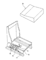
図1は本発明に係る車両シートにおけるワイヤハーネス配索構造の一実施形態の分解斜視図、図2は図1に示した車両シート下部のサイドフレームからシート内部にワイヤハーネスを導入した状態を示す斜視図、図3は図1に示したワイヤハーネス配索構造において、車両シート下部のサイドフレーム上に装備した保護プロテクタによってサイドフレームとクッションパンとが連結されている状態を示す拡大断面図である。 FIG. 1 is an exploded perspective view of an embodiment of a wire harness routing structure in a vehicle seat according to the present invention, and FIG. 2 shows a state in which the wire harness is introduced into the seat from the side frame below the vehicle seat shown in FIG. FIG. 3 is an enlarged cross-sectional view showing a state in which the side frame and the cushion pan are connected by a protective protector installed on the side frame below the vehicle seat in the wire harness routing structure shown in FIG. .
この一実施形態の車両シートにおけるワイヤハーネス配索構造は、ワイヤハーネス9が、車両シート下部のサイドフレーム11からシート内部に導入されて、シート内部の各部に配索される車両シートにおけるワイヤハーネス配索構造である。
The wire harness wiring structure in the vehicle seat according to this embodiment is configured such that the
ワイヤハーネス9は、シート外部に引き出される供給側端部9aにコネクタ13が接続されている。このコネクタ13は、車室側の他のハーネスにコネクタ接続される。ワイヤハーネス9のシート内部側は、複数の枝ハーネス9b,9c,9dに分岐されていて、シート内の各電動部(電気機器)に接続される。
The
本実施形態の場合、ワイヤハーネス9のシート内部側となる部位は、サイドフレーム11の上縁を跨いで、シート外部からシート内部に導入される。
In the case of this embodiment, the site | part which becomes the sheet | seat inside side of the
本実施形態の場合、サイドフレーム11のワイヤハーネス9が跨ぐ部位には、ワイヤハーネス9が直接サイドフレーム11に接触することを防止する保護プロテクタ15を装備している。
In the case of this embodiment, the
この保護プロテクタ15は、樹脂製で、サイドフレーム11の上縁に形成された角形の切り欠き部11aに嵌合装着される。本実施形態の場合、サイドフレーム11には、切り欠き部11aが2箇所形成されていて、図2に示すように、2つの保護プロテクタ15が装備される。
The
保護プロテクタ15は、切り欠き部11aの幅寸法W1に略等しい幅寸法W2で対向配置された一対の側壁部15a,15bと、これらの側壁部15a,15b間を連結すると共に、ワイヤハーネス9がサイドフレーム11に直接接触しないように切り欠き部11aの底部側を覆うハーネス載置部15cとを備えている。
The
更に、本実施形態の保護プロテクタ15は、図3に示すように、サイドフレーム11に係合する第1のフレーム係合部17と、クッションパン21に係合するパン係合部18とが設けられている。
Further, as shown in FIG. 3, the
第1のフレーム係合部17は、図3に示すように、サイドフレーム11の切り欠き部11aの底部の膨出部19を、該膨出部19の裏側に係合する鉤形のアーム部17aと、サイドフレーム11の表側に位置する押さえ片17bとで挾持するようにしたものである。押さえ片17bは、サイドフレーム11の表面に重なるハーネス載置部15cの端部である。
As shown in FIG. 3, the first
なお、本実施形態の保護プロテクタ15は、前述した一対の側壁部15a,15bが、切り欠き部11aに嵌合して、サイドフレーム11との係合を果たす第2のフレーム係合部として機能し、第1及び第2の二つのフレーム係合部によって、サイドフレーム11にしっかりと結合されるようになっている。
The
クッションパン21は、サイドフレーム11の上に装着されるシートクッション25の裏面に裏打ちされる金属製の支持プレートである。
The
保護プロテクタ15に装備されたパン係合部18は、図3に示すように、クッションパン21に貫通形成された係合孔21aに係合する鉤状の係止片で、係合孔21aとの係合により、クッションパン21との連結を果たす。
As shown in FIG. 3, the
本実施形態の保護プロテクタ15は、上記のように、第1のフレーム係合部17及び第2のフレーム係合部としての一対の側壁部15a,15bがサイドフレーム11に係合することによりサイドフレーム11に固定され、また、パン係合部18がクッションパン21の係合孔21aに係合することによりクッションパン21に固定される。これにより、保護プロテクタ15を介して、サイドフレーム11とクッションパン21とが、連結状態になる。
As described above, the
以上に説明した本実施形態のワイヤハーネス配索構造では、ワイヤハーネス9をシート外部から車両シート内に導入する際、又は車両シート内からワイヤハーネス9をシート外部に引き出す際には、ワイヤハーネス9を車両シート下部のサイドフレーム11の上縁を跨がせるため、サイドフレーム11に形成されたハーネス挿通孔にワイヤハーネスを挿通しなければならなかった従来と比較すると、ワイヤハーネス9の導出入が容易になり、配索作業性を向上させることができる。
In the wire harness routing structure of the present embodiment described above, when the
また、サイドフレーム11上のワイヤハーネス9が跨ぐ部位には、ワイヤハーネス9が直接サイドフレーム11に接触することを防止する保護プロテクタ15が装備されているため、サイドフレーム11との噛み込み等によってワイヤハーネス9が損傷することを防止して、ワイヤハーネス9の耐久性を向上させることができる。
In addition, a
更に、上記構成によれば、保護プロテクタ15は、サイドフレーム11の上に装着されるクッションパン21及びサイドフレーム11に係合しているため、保護プロテクタ15が不用意に脱落することがなく、保護プロテクタ15によるワイヤハーネス9の保持を安定させることができる。
Furthermore, according to the above configuration, since the
更に、本実施形態の場合、保護プロテクタ15にはサイドフレーム11に係合するフレーム係合部17と、クッションパン21に係合するパン係合部18とが設けられ、保護プロテクタ15を介してサイドフレーム11とクッションパン21とを連結状態にしている。
Further, in the case of the present embodiment, the
即ち、ワイヤハーネス9を保護する保護プロテクタ15が、サイドフレーム11とクッションパン21とを連結する連結手段を兼ねることになり、保護プロテクタ15をより有用に活用することができる。
That is, the
なお、上記実施形態では、保護プロテクタ15に、サイドフレーム11に係合するフレーム係合部17と、クッションパン21に係合するパン係合部18との双方を設けた。
In the above-described embodiment, the
しかし、例えば保護プロテクタ15が不用意に脱落することを防止する目的だけであれば、フレーム係合部17およびパン係合部18のいずれか一方のみを装備し、クッションパン21またはサイドフレーム11のいずれか一方にのみ係合させる構成としても良い。
However, for example, for the purpose of preventing the
即ち、保護プロテクタ15は、クッションパン21またはサイドフレーム11の少なくとも一方に係合させる構成としておけば良い。
That is, the
なお、本発明は、上述した実施形態に限定されるものではなく、適宜、変形、改良等が自在である。その他、上述した実施形態における各構成要素の材質、形状、寸法、数値、形態、数、配置場所、等は本発明を達成できるものであれば任意であり、限定されない。 In addition, this invention is not limited to embodiment mentioned above, A deformation | transformation, improvement, etc. are possible suitably. In addition, the material, shape, dimension, numerical value, form, number, arrangement location, and the like of each component in the above-described embodiment are arbitrary and are not limited as long as the present invention can be achieved.
9 ワイヤハーネス
11 サイドフレーム
11a 切り欠き部
15 保護プロテクタ
15a,15b 側壁部(第2のフレーム係合部)
15c ハーネス載置部
17 第1のフレーム係合部
18 パン係合部
21 クッションパン
25 シートクッション
9
15c
Claims (2)
前記サイドフレームから前記車両シート内に導入されて前記車両シート内部の各部に配索されるワイヤハーネスと、
を備えた、車両におけるワイヤハーネス配索構造であって、
前記ワイヤハーネスは、前記サイドフレームの上縁を跨いで、前記車両シート外部から前記車両シート内部に導入され、
前記サイドフレームの前記ワイヤハーネスが跨ぐ部位には、前記ワイヤハーネスが直接前記サイドフレームに接触することを防止する保護プロテクタが装備されると共に、該保護プロテクタは前記クッションパン及び前記サイドフレームの少なくとも一方に係合されたことを特徴とする車両シートにおけるワイヤハーネス配索構造。 A vehicle seat having a side frame and a cushion pan mounted on the side frame;
A wire harness introduced from the side frame into the vehicle seat and routed to each part inside the vehicle seat;
A wiring harness wiring structure in a vehicle, comprising:
The wire harness is introduced into the vehicle seat from outside the vehicle seat, straddling the upper edge of the side frame,
A protective protector for preventing the wire harness from coming into direct contact with the side frame is provided at a portion of the side frame where the wire harness is straddled, and the protective protector is at least one of the cushion pan and the side frame. The wire harness wiring structure in the vehicle seat characterized by being engaged with the vehicle seat.
Priority Applications (1)
| Application Number | Priority Date | Filing Date | Title |
|---|---|---|---|
| JP2008097216A JP5264252B2 (en) | 2008-04-03 | 2008-04-03 | Wire harness wiring structure in vehicle seat |
Applications Claiming Priority (1)
| Application Number | Priority Date | Filing Date | Title |
|---|---|---|---|
| JP2008097216A JP5264252B2 (en) | 2008-04-03 | 2008-04-03 | Wire harness wiring structure in vehicle seat |
Publications (2)
| Publication Number | Publication Date |
|---|---|
| JP2009248676A true JP2009248676A (en) | 2009-10-29 |
| JP5264252B2 JP5264252B2 (en) | 2013-08-14 |
Family
ID=41309779
Family Applications (1)
| Application Number | Title | Priority Date | Filing Date |
|---|---|---|---|
| JP2008097216A Active JP5264252B2 (en) | 2008-04-03 | 2008-04-03 | Wire harness wiring structure in vehicle seat |
Country Status (1)
| Country | Link |
|---|---|
| JP (1) | JP5264252B2 (en) |
Cited By (3)
| Publication number | Priority date | Publication date | Assignee | Title |
|---|---|---|---|---|
| US9039081B2 (en) | 2011-11-14 | 2015-05-26 | Ford Global Technologies, Llc | Wire harness for a vehicle seating assembly |
| JP2019023013A (en) * | 2017-07-24 | 2019-02-14 | 株式会社タチエス | Seat frame |
| JP2021070383A (en) * | 2019-10-30 | 2021-05-06 | トヨタ紡織株式会社 | Cushion frame |
Citations (3)
| Publication number | Priority date | Publication date | Assignee | Title |
|---|---|---|---|---|
| JPH0296218U (en) * | 1989-01-13 | 1990-07-31 | ||
| JPH062923U (en) * | 1992-06-03 | 1994-01-14 | 株式会社カンセイ | Protector for harness |
| JPH08244507A (en) * | 1995-03-08 | 1996-09-24 | Mitsubishi Motors Corp | Fixing structure of rope-like body in seat |
-
2008
- 2008-04-03 JP JP2008097216A patent/JP5264252B2/en active Active
Patent Citations (3)
| Publication number | Priority date | Publication date | Assignee | Title |
|---|---|---|---|---|
| JPH0296218U (en) * | 1989-01-13 | 1990-07-31 | ||
| JPH062923U (en) * | 1992-06-03 | 1994-01-14 | 株式会社カンセイ | Protector for harness |
| JPH08244507A (en) * | 1995-03-08 | 1996-09-24 | Mitsubishi Motors Corp | Fixing structure of rope-like body in seat |
Cited By (8)
| Publication number | Priority date | Publication date | Assignee | Title |
|---|---|---|---|---|
| US9039081B2 (en) | 2011-11-14 | 2015-05-26 | Ford Global Technologies, Llc | Wire harness for a vehicle seating assembly |
| US9073468B2 (en) | 2011-11-14 | 2015-07-07 | Ford Global Technologies, Llc | Vehicle seat bracket assembly |
| US9108553B2 (en) | 2011-11-14 | 2015-08-18 | Ford Global Technologies, Llc | Vehicle seat suspension system |
| US9376043B2 (en) | 2011-11-14 | 2016-06-28 | Ford Global Technologies, Llc | Cushion pan for a vehicle seat assembly |
| US10232752B2 (en) | 2011-11-14 | 2019-03-19 | Fod Global Technologies, LLC | Cushion pan for a vehicle seat assembly |
| JP2019023013A (en) * | 2017-07-24 | 2019-02-14 | 株式会社タチエス | Seat frame |
| JP2021070383A (en) * | 2019-10-30 | 2021-05-06 | トヨタ紡織株式会社 | Cushion frame |
| JP7227886B2 (en) | 2019-10-30 | 2023-02-22 | トヨタ紡織株式会社 | cushion frame |
Also Published As
| Publication number | Publication date |
|---|---|
| JP5264252B2 (en) | 2013-08-14 |
Similar Documents
| Publication | Publication Date | Title |
|---|---|---|
| JP5264254B2 (en) | Wire harness wiring structure in vehicle seat | |
| JP2009137390A (en) | Holding structure for electric wiring member at vehicle seat | |
| JP5960310B2 (en) | Wire harness wiring structure | |
| JP5264252B2 (en) | Wire harness wiring structure in vehicle seat | |
| JP6564813B2 (en) | Protective case for electric wire | |
| JP2007276628A (en) | Wiring structure of wiring harness | |
| JP4827594B2 (en) | Wire harness wiring structure | |
| JP2010009866A (en) | Wire harness wiring structure | |
| US8424698B2 (en) | Case and method for unlocking the case | |
| JP5264253B2 (en) | Wire harness wiring structure in vehicle seat | |
| JP2011101511A (en) | Junction block structure | |
| US11485300B2 (en) | Wire harness protector and routing structure of wire harness using wire harness protector | |
| JP4757731B2 (en) | Wiring structure for headrest | |
| JP6056732B2 (en) | Wire harness routing device for slide sheet | |
| JP4600333B2 (en) | Electrical junction box | |
| JP2006321410A (en) | Seat module for automobile and on-the-body mounting structure of seat module | |
| JP4890031B2 (en) | Temporary clamp | |
| JP2008155812A (en) | Instrument panel reinforcement | |
| JP7400464B2 (en) | Harness protection structure | |
| JP5703011B2 (en) | Wire harness ground connection structure | |
| JP5189465B2 (en) | Protector | |
| JP6529539B2 (en) | Vehicle seat device | |
| JP2019048492A (en) | Power supply device | |
| JP2005259608A (en) | Structure for connecting wire to connector | |
| JP5788674B2 (en) | Cabling structure |
Legal Events
| Date | Code | Title | Description |
|---|---|---|---|
| A621 | Written request for application examination |
Free format text: JAPANESE INTERMEDIATE CODE: A621 Effective date: 20110225 |
|
| A131 | Notification of reasons for refusal |
Free format text: JAPANESE INTERMEDIATE CODE: A131 Effective date: 20130129 |
|
| A521 | Request for written amendment filed |
Free format text: JAPANESE INTERMEDIATE CODE: A523 Effective date: 20130312 |
|
| TRDD | Decision of grant or rejection written | ||
| A01 | Written decision to grant a patent or to grant a registration (utility model) |
Free format text: JAPANESE INTERMEDIATE CODE: A01 Effective date: 20130402 |
|
| A61 | First payment of annual fees (during grant procedure) |
Free format text: JAPANESE INTERMEDIATE CODE: A61 Effective date: 20130430 |
|
| R150 | Certificate of patent or registration of utility model |
Free format text: JAPANESE INTERMEDIATE CODE: R150 Ref document number: 5264252 Country of ref document: JP Free format text: JAPANESE INTERMEDIATE CODE: R150 |
|
| R250 | Receipt of annual fees |
Free format text: JAPANESE INTERMEDIATE CODE: R250 |
|
| R250 | Receipt of annual fees |
Free format text: JAPANESE INTERMEDIATE CODE: R250 |
|
| R250 | Receipt of annual fees |
Free format text: JAPANESE INTERMEDIATE CODE: R250 |
|
| R250 | Receipt of annual fees |
Free format text: JAPANESE INTERMEDIATE CODE: R250 |
|
| R250 | Receipt of annual fees |
Free format text: JAPANESE INTERMEDIATE CODE: R250 |
|
| R250 | Receipt of annual fees |
Free format text: JAPANESE INTERMEDIATE CODE: R250 |
|
| R250 | Receipt of annual fees |
Free format text: JAPANESE INTERMEDIATE CODE: R250 |
|
| R250 | Receipt of annual fees |
Free format text: JAPANESE INTERMEDIATE CODE: R250 |
|
| S531 | Written request for registration of change of domicile |
Free format text: JAPANESE INTERMEDIATE CODE: R313531 |
|
| R350 | Written notification of registration of transfer |
Free format text: JAPANESE INTERMEDIATE CODE: R350 |