JP2005297619A - Reflective mirror device and vehicle display device - Google Patents
Reflective mirror device and vehicle display device Download PDFInfo
- Publication number
- JP2005297619A JP2005297619A JP2004112676A JP2004112676A JP2005297619A JP 2005297619 A JP2005297619 A JP 2005297619A JP 2004112676 A JP2004112676 A JP 2004112676A JP 2004112676 A JP2004112676 A JP 2004112676A JP 2005297619 A JP2005297619 A JP 2005297619A
- Authority
- JP
- Japan
- Prior art keywords
- base unit
- reflection mirror
- vehicle
- mirror device
- display
- Prior art date
- Legal status (The legal status is an assumption and is not a legal conclusion. Google has not performed a legal analysis and makes no representation as to the accuracy of the status listed.)
- Withdrawn
Links
Images

Landscapes
- Instrument Panels (AREA)
Abstract
【課題】装置本体の組付に応じて生じる不具合を解消する反射ミラー装置する。
【解決手段】 車両のダッシュボード1に対して起立及び傾倒可能に設けられるベースユニット11と、該ベースユニット11によって予め定められた回動範囲内にて回動可能に軸支される反射ミラー12と、を備え、ベースユニット11の起立状態における反射ミラー12の角度を回動範囲内で調整することにより、ダッシュボード1内に収容された発光表示部2からの表示光の光路Lを車両の乗員のアイポイントIに向けて反射させる反射ミラー装置10において、ベースユニット11が起立状態となったときに当該ベースユニット11の起立動作を阻止する阻止部材16と、ベースユニット11の起立状態における反射ミラー12の回動範囲が、車両のアイレンジに対応した回動範囲となるように、阻止部材16の取付位置を調整する調整手段17,18,19と、を備える。
【選択図】図1A reflection mirror device that eliminates problems caused by assembly of a device main body.
A base unit 11 is provided so as to be able to stand and tilt with respect to a dashboard 1 of a vehicle, and a reflecting mirror 12 is pivotally supported by the base unit 11 so as to be rotatable within a predetermined rotation range. And adjusting the angle of the reflection mirror 12 in the standing state of the base unit 11 within the rotation range, thereby changing the optical path L of the display light from the light emitting display unit 2 housed in the dashboard 1 of the vehicle In the reflection mirror device 10 that reflects toward the occupant's eye point I, a blocking member 16 that prevents the base unit 11 from standing when the base unit 11 is in the standing state, and reflection in the standing state of the base unit 11. The adjustment position of the blocking member 16 is adjusted so that the rotation range of the mirror 12 is a rotation range corresponding to the eye range of the vehicle. Adjusting means 17, 18, 19.
[Selection] Figure 1
Description
本発明は、反射ミラー装置及び車両用表示装置に関し、より詳細には、車両のダッシュボードに対して起立及び傾倒可能に設けられるベースユニットと、該ベースユニットによって予め定められた回動範囲内にて回動可能に軸支される反射ミラーと、を備え、前記ベースユニットの起立状態における前記反射ミラーの角度を前記回動範囲内で調整することにより、前記ダッシュボード内に収容された発光表示部からの表示光の光路を前記車両の乗員のアイポイントに向けて反射させる反射ミラー装置、及び、該反射ミラー装置を備える車両用表示装置に関するものである。 The present invention relates to a reflection mirror device and a display device for a vehicle, and more specifically, a base unit provided so as to be able to stand up and tilt with respect to a dashboard of a vehicle, and within a rotation range predetermined by the base unit. A reflective mirror that is pivotally supported in a rotatable manner, and adjusting the angle of the reflective mirror in the standing state of the base unit within the rotational range so that the light-emitting display accommodated in the dashboard The present invention relates to a reflection mirror device that reflects an optical path of display light from a section toward an eyepoint of an occupant of the vehicle, and a vehicle display device including the reflection mirror device.
近年、運転者が運転に際して求める情報の増加や多角化に伴って、メータユニット内ではスペースの関係上表示しきれない情報を、フロントガラス上に虚像を表示させ、それを透して視認させる車両の前景と重畳視認させる、ヘッドアップディスプレイ装置(HUD)と呼ばれる投影型表示ユニットが採用されている。 In recent years, with the increase and diversification of information required by the driver during driving, a vehicle that displays a virtual image on the windshield and visually displays information that cannot be displayed due to space in the meter unit A projection display unit called a head-up display device (HUD) that allows the foreground to be superimposed and viewed is used.
また、人間が外部から受け取る情報のメインは視覚を通じてのものといわれており、車両を運転している場合には、視覚の重要性が非常に高くなっている。そのため、進行方向に控える障害物を早く察知すればするほど、余裕を持って対応できるため、夜間や悪条件下での視界確保を目的とし、安全な走行を支援する夜間運転視界支援装置(ナイトビジョン)が市販されている。 In addition, it is said that the main information that humans receive from outside is through vision, and when driving a vehicle, the importance of vision is very high. Therefore, the earlier you detect obstacles in the direction of travel, the more you can respond, so the night driving vision support device (night driving) that supports safe driving for the purpose of securing visibility at night and in adverse conditions. Vision) is commercially available.
このナイトビジョンは、車体前部に設置した赤外線カメラ、コンピュータ、上述したHUDを有して構成されている。そして、赤外線カメラによって物体が放射する赤外線(熱)情報を運転者前のHUDによりモノクロ画像の虚像として映し出すことで、闇に潜む見えない障害物、雨や霧で視界が開けないときの車両前方の障害物等を運転者に認識させている。 This night vision has an infrared camera, a computer, and the above-described HUD installed at the front of the vehicle body. Infrared (heat) information radiated from the object by the infrared camera is projected as a virtual image of a monochrome image by the HUD in front of the driver, so that invisible obstacles lurking in the darkness, rain or fog can not open the front of the vehicle The driver is made aware of obstacles.
HUD表示は、HUD表示光をコンバイナ、ウインドシールド(フロントガラス)等の投影部材で反射させ、運転視界内で表示を運転者に視認させている。つまり、表示位置を従来のメータや表示に比べて、運転者が表示を見るために目線を下に落とす角度を小さくして、視線移動時間を短くしたり、表示距離を遠方とすることで、車両の前景から表示に目を移す際の、目の焦点合わせを楽にするなどのメリットを狙っている。 In the HUD display, HUD display light is reflected by a projection member such as a combiner or a windshield (front glass) to make the display visible to the driver within the driving field of view. In other words, compared to conventional meters and displays, the display position can be reduced by reducing the angle at which the driver looks down to see the display, shortening the eye movement time, and making the display distance far. The aim is to make it easier to focus the eyes when moving from the foreground to the display.
また、ナイトビジョンなどのような大型のHUDでは、昼間の使用はなく、車両の前方の視界は広くとることが望ましいことから、コンバイナに回動機構を設け、未使用時にはコンバイナを車両のインストルメントパネル等の内部に格納するようにしている。 In addition, large HUDs such as night vision are not used in the daytime and it is desirable to have a wide field of view in front of the vehicle. Therefore, the combiner is provided with a rotation mechanism, and the combiner is installed in the vehicle instrument when not in use. It is stored inside the panel.
そこで、表示源を虚像として遠方に視認させるために乗員のアイポイントの前方に配置した反射ミラーを、表示源の遠方表示を必要としないときには、アイポイントから虚像表示された表示源に至る視線上から退避させることができるように、折り畳み式の反射ミラーを採用することが、従来から既に提案されている(例えば特許文献1)。
しかしながら、ヘッドアップディスプレイ装置(HUD)を車両に取り付ける際、予め定められた取付位置に対する前後方向の公差から実際の取付位置がずれてしまうと、コンバイナの初期角度がずれてしまい、アイレンジの全てをカバーするためには、コンバイナ内のミラー角度調整機構のマージンを大きくする必要があった。そのため、コンバイナの厚みが大きくなりすぎてしまい、コンバイナの未使用時に、その大きさを包括する場合、その収容スペースが大きくなるという問題が発生する。また、ミラーの角度調整幅が大きくなってしまい、調整に要する時間が長くなって煩わしいという問題も発生する。 However, when the head-up display device (HUD) is attached to the vehicle, if the actual attachment position deviates from the tolerance in the front-rear direction with respect to the predetermined attachment position, the initial angle of the combiner will deviate, and the entire eye range In order to cover this, it is necessary to increase the margin of the mirror angle adjustment mechanism in the combiner. For this reason, the thickness of the combiner becomes too large, and when the combiner is not used, when the size is included, there arises a problem that the accommodation space becomes large. Further, the angle adjustment width of the mirror becomes large, and there is a problem that the time required for adjustment becomes long and troublesome.
よって本発明は、上述した問題点に鑑み、装置本体の組付に応じて生じる不具合を解消する反射ミラー装置及び車両用表示装置を提供することを課題としている。 Therefore, in view of the above-described problems, an object of the present invention is to provide a reflection mirror device and a vehicle display device that solve problems caused by the assembly of the device main body.
上記課題を解決するため本発明によりなされた請求項1記載の反射ミラー装置は、図1の基本構成図に示すように、車両のダッシュボードに対して起立及び傾倒可能に設けられるベースユニットと、該ベースユニットによって予め定められた回動範囲内にて回動可能に軸支される反射ミラーと、を備え、前記ベースユニットの起立状態における前記反射ミラーの角度を前記回動範囲内で調整することにより、前記ダッシュボード内に収容された発光表示部からの表示光の光路を前記車両の乗員のアイポイントに向けて反射させる反射ミラー装置において、前記ベースユニットが前記起立状態となったときに当該ベースユニットの起立動作を阻止する阻止部材と、前記ベースユニットの起立状態における前記反射ミラーの前記回動範囲が、前記車両のアイレンジに対応した回動範囲となるように、前記阻止部材の取付位置を調整する調整手段と、を備えることを特徴とする。 In order to solve the above-mentioned problems, the reflection mirror device according to claim 1 made according to the present invention, as shown in the basic configuration diagram of FIG. 1, a base unit provided so as to be able to stand up and tilt with respect to a dashboard of a vehicle, And a reflection mirror pivotally supported by the base unit so as to be rotatable within a predetermined rotation range, and adjusting the angle of the reflection mirror in the standing state of the base unit within the rotation range. Accordingly, in the reflection mirror device that reflects the optical path of the display light from the light emitting display unit accommodated in the dashboard toward the eye point of the vehicle occupant, when the base unit is in the standing state A blocking member that prevents the base unit from being raised, and the rotation range of the reflection mirror in the standing state of the base unit includes As the rotation range corresponding to both of the eye range, characterized in that it comprises an adjustment means for adjusting the mounting position of the blocking member.
上記請求項1に記載した本発明の反射ミラー装置によれば、ダッシュボードに組み付けられた後等に、ベースユニットの起立状態における反射ミラーの回動範囲が、車両における乗員のアイポイントの分布を示すアイレンジに対応した回動範囲となるように、阻止部材の取付位置は調整手段によって調整される。そして、ベースユニットが開始した傾倒状態から起立状態へ移行する起立動作は阻止部材によって阻止されると、ベースユニットは起立状態となる。そして、ダッシュボード内に収容された発光表示部からの表示光の光路を車両の乗員のアイポイントに向けて反射させるように、反射ミラーの角度を車両のアイレンジに対応した回動範囲内で調整される。 According to the reflection mirror device of the present invention described in claim 1, after being assembled to the dashboard, the rotation range of the reflection mirror in the standing state of the base unit is the distribution of the occupant's eyepoints in the vehicle. The attachment position of the blocking member is adjusted by the adjusting means so that the rotation range corresponds to the eye range shown. And if the standing operation which transfers to the standing state from the tilting state which the base unit started is blocked | prevented by the blocking member, a base unit will be in a standing state. Then, the angle of the reflection mirror is set within the rotation range corresponding to the eye range of the vehicle so that the optical path of the display light from the light emitting display unit housed in the dashboard is reflected toward the eye point of the vehicle occupant. Adjusted.
上記課題を解決するためになされた請求項2記載の発明は、図1の基本構成図に示すように、請求項1に記載の反射ミラー装置において、前記阻止部材は、前記ベースユニットの一部と係止して前記起立動作を阻止するように構成されており、前記調整手段は、前記ベースユニットが前記阻止部材に係止した状態で、前記ベースユニットから前記阻止部材に伝達される外力を吸収するように構成されていることを特徴とする。 According to a second aspect of the present invention, there is provided a reflection mirror device according to the first aspect, wherein the blocking member is a part of the base unit. The adjusting means is configured to prevent external force transmitted from the base unit to the blocking member in a state where the base unit is locked to the blocking member. It is configured to absorb.
上記請求項2に記載した本発明の反射ミラー装置によれば、ベースユニットはその一部が阻止部材に係止すると、起立動作が阻止されて起立状態となる。この状態で、ベースユニットに不意な外力が加えられ、その外力がベースユニットから阻止部材に伝達されると、その外力は調整手段を構成する例えば、弾性部材、吸収部材等によって吸収される。 According to the reflection mirror device of the present invention described in the second aspect, when a part of the base unit is locked to the blocking member, the rising operation is blocked and the standing unit is brought up. In this state, when an unexpected external force is applied to the base unit and the external force is transmitted from the base unit to the blocking member, the external force is absorbed by, for example, an elastic member, an absorbing member, or the like that constitutes the adjusting means.
上記課題を解決するため本発明によりなされた請求項3記載の車両用表示装置は、図1の基本構成図に示すように、車両のダッシュボード内に収容された発光表示源と、該発光表示源からの表示光を前記車両の乗員のアイポイントに向けて反射させる反射ミラー装置とを有する車両用表示装置であって、前記反射ミラー装置として請求項1又は2記載の反射ミラー装置を用いることを特徴とする。 In order to solve the above problems, a vehicle display device according to claim 3 according to the present invention comprises a light emitting display source housed in a dashboard of a vehicle, and the light emitting display as shown in the basic configuration diagram of FIG. A display device for a vehicle having a reflection mirror device that reflects display light from a light source toward an eyepoint of an occupant of the vehicle, wherein the reflection mirror device according to claim 1 or 2 is used as the reflection mirror device. It is characterized by.
上記請求項3に記載した本発明の車両用表示装置によれば、発光表示源と反射ミラー装置はダッシュボード内に組み付けられる。そして、ベースユニットの起立状態における反射ミラーの回動範囲が、車両における乗員のアイポイントの分布を示すアイレンジに対応した回動範囲となるように、阻止部材の取付位置は調整手段によって調整される。そして、ベースユニットが開始した傾倒状態から起立状態へ移行する起立動作は阻止部材によって阻止されると、ベースユニットは起立状態となる。そして、ダッシュボード内に収容された発光表示部からの表示光の光路を車両の乗員のアイポイントに向けて反射させるように、反射ミラーの角度を車両のアイレンジに対応した回動範囲内で調整される。 According to the vehicle display device of the present invention described in claim 3, the light emitting display source and the reflection mirror device are assembled in the dashboard. Then, the attachment position of the blocking member is adjusted by the adjusting means so that the turning range of the reflecting mirror in the standing state of the base unit is a turning range corresponding to the eye range indicating the distribution of eye points of the occupants in the vehicle. The And if the standing operation which transfers to the standing state from the tilting state which the base unit started is blocked | prevented by the blocking member, a base unit will be in a standing state. Then, the angle of the reflection mirror is set within the rotation range corresponding to the eye range of the vehicle so that the optical path of the display light from the light emitting display unit housed in the dashboard is reflected toward the eye point of the vehicle occupant. Adjusted.
以上説明したように請求項1に記載した本発明の反射ミラー装置によれば、ベースユニットの起立状態における反射ミラーの回動範囲が、車両における乗員のアイポイントの分布を示すアイレンジに対応した回動範囲となるように、阻止部材の取付位置の調整を可能な構成としたことから、反射ミラー装置が本来の組付位置からずれた位置に取り付けられても、反射ミラーの回動範囲はアイレンジに対応した回動範囲に修正することができる。従って、ベースユニットの起立角度によって反射ミラーの回動範囲を画定して車両のアイレンジをカバーする構成であっても、装置本体の取付位置のずれによる悪影響を排除することができる。また、アイレンジの全てをカバーするために、ベースユニットの反射ミラーの回動範囲を大きくする必要もないことから、ベースユニット、装置本体等の小型化を図ることができる。さらに、ベースユニットの起立角度の調整を可能とすることで、反射ミラーの回動範囲も小さくすることができるため、調整時間が短縮され、反射ミラーの調整作業の効率化を図ることができる。 As described above, according to the reflection mirror device of the present invention described in claim 1, the rotation range of the reflection mirror in the standing state of the base unit corresponds to the eye range indicating the distribution of the occupant's eye points in the vehicle. Since the attachment position of the blocking member can be adjusted so as to be in the rotation range, even if the reflection mirror device is attached at a position shifted from the original assembly position, the rotation range of the reflection mirror is The rotation range corresponding to the eye range can be corrected. Accordingly, even if the rotation range of the reflecting mirror is defined by the standing angle of the base unit to cover the eye range of the vehicle, it is possible to eliminate an adverse effect due to a shift in the mounting position of the apparatus main body. Further, since it is not necessary to increase the rotation range of the reflection mirror of the base unit in order to cover the entire eye range, the base unit, the apparatus main body, etc. can be reduced in size. Furthermore, by making it possible to adjust the standing angle of the base unit, it is possible to reduce the rotation range of the reflection mirror, thereby shortening the adjustment time and increasing the efficiency of the adjustment operation of the reflection mirror.
請求項2に記載の発明によれば、請求項1に記載の発明の効果に加え、ベースユニットと阻止部材が係止状態に係止した状態で、ベースユニットに不意な外力が加えられ、その外力がベースユニットを介して阻止部材に伝達されても、その外力は調整手段によって吸収するように構成したことから、阻止部材に伝達される外力を逃がすことができるため、阻止手段の外力による破損を防止することができる。 According to the invention described in claim 2, in addition to the effect of the invention described in claim 1, in the state where the base unit and the blocking member are locked in the locked state, an unexpected external force is applied to the base unit. Even if an external force is transmitted to the blocking member via the base unit, the external force is absorbed by the adjusting means, so that the external force transmitted to the blocking member can be released. Can be prevented.
以上説明したように請求項3に記載した本発明の車両用表示装置によれば、反射ミラー装置は、ベースユニットの起立状態における反射ミラーの回動範囲が、車両における乗員のアイポイントの分布を示すアイレンジに対応した回動範囲となるように、阻止部材の取付位置を調整することができるため、反射ミラー装置が車両毎に異なる取付位置に取り付けられても、反射ユニットの回動範囲にて車両のアイレンジを確実にカバーすることができる。また、アイレンジの全てをカバーするために、ベースユニットの反射ミラーの回動範囲を大きくする必要もないことから、ベースユニット、装置本体等の小型化を図ることができる。さらに、ベースユニットの起立角度の調整を可能とすることで、反射ミラーの回動範囲も小さくすることができるため、調整時間が短縮され、反射ミラーの調整作業の効率化を図ることができる。 As described above, according to the vehicle display device of the present invention described in claim 3, the reflection mirror device is configured such that the rotation range of the reflection mirror in the standing state of the base unit is the distribution of the occupant eyepoints in the vehicle. Since the attachment position of the blocking member can be adjusted so that the rotation range corresponds to the eye range shown, even if the reflection mirror device is attached to a different attachment position for each vehicle, the rotation range of the reflection unit is maintained. This can reliably cover the eye range of the vehicle. Further, since it is not necessary to increase the rotation range of the reflection mirror of the base unit in order to cover the entire eye range, the base unit, the apparatus main body, etc. can be reduced in size. Furthermore, by making it possible to adjust the standing angle of the base unit, it is possible to reduce the rotation range of the reflection mirror, thereby shortening the adjustment time and increasing the efficiency of the adjustment operation of the reflection mirror.
以下、本発明に係る反射ミラー装置を備える車両用表示装置の一実施の形態を、図1〜図4の図面を参照して説明する。 Hereinafter, an embodiment of a display device for a vehicle provided with a reflection mirror device according to the present invention will be described with reference to the drawings of FIGS.
図1は本発明の反射ミラー装置及び車両用表示装置の概略構成の一例を説明するための図であり、図2はストッパの固定の一例を説明するための図であり、図3は反射ミラー装置と角度調整治具との関係を説明するための図であり、図4(A)及び図4(B)はぞれぞれ、ベースユニットの適切及び不適切な状態を示す図である。 FIG. 1 is a diagram for explaining an example of a schematic configuration of a reflection mirror device and a vehicle display device of the present invention, FIG. 2 is a diagram for explaining an example of fixing a stopper, and FIG. 3 is a diagram of a reflection mirror. It is a figure for demonstrating the relationship between an apparatus and an angle adjustment jig, and FIG. 4 (A) and FIG.4 (B) are the figures which show the appropriate and unsuitable state of a base unit, respectively.
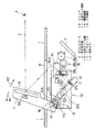
図1に示す車両用表示装置は、車両のダッシュボード1の上面に形成された開口部1aを開閉するように、ダッシュボード1内に収容される発光表示源2と、該発光表示源2からの表示光Lを車両の乗員のアイポイントIに向けて反射させる反射ミラー装置10と、を備える。そして、発光表示源2と反射ミラー装置10は、ダッシュボード1内に組み付けている。
The vehicle display device shown in FIG. 1 includes a light emitting display source 2 housed in the dashboard 1 so as to open and close an opening 1 a formed on the upper surface of the dashboard 1 of the vehicle, and the light emitting display source 2. The
発光表示源2は、例えば、ナビゲーション等に対応する画像表示光を発する。この表示器2としては、例えば、蛍光表示管やバックライト付きの液晶表示器を用いることができる。そして、ダッシュボード1内に取り付け部材等によって固定される。 The light emitting display source 2 emits image display light corresponding to navigation or the like, for example. For example, a fluorescent display tube or a liquid crystal display with a backlight can be used as the display 2. And it fixes in the dashboard 1 with an attachment member.
反射ミラー装置10は、ダッシュボード1に対して起立及び傾倒可能に設けられるベースユニット11と、該ベースユニット11によって予め定められた回動範囲内にて回動可能に軸支される反射ミラー12と、を備える。そして、反射ミラー装置10のハウジング10aは、ダッシュボード1内で取付部材等によって固定される。
The
なお、本最良の形態において起立状態とは、ベースユニット11によってダッシュボード1の開口部1aを開放し、発光表示源2からの表示光が開口部1aの通過が可能となった状態であり、また、傾倒状態とは、ベースユニット11によって開口部1aを塞いだ状態である。
In the best mode, the standing state is a state in which the opening 1a of the dashboard 1 is opened by the
ベースユニット11は、回動軸13を回動中心として回動可能なようにハウジング10aに取り付けられる。回動軸13は、ベースユニット11の起立状態及び傾倒状態への動作させる駆動力を発生するモータ14に、複数のギアが歯合されたギア群15を介して接続している。そして、モータ14は、所定のスイッチ操作、制御ユニットからの要求等に応じて駆動され、その駆動力はギア群15によって回動軸13に伝達され、回動軸13を回動させる。
The
図1に示す起立状態にする場合、図1中矢印の方向A1にベースユニット11を回動させるように、回動軸13がモータ14によって回動される。また、傾倒状態にする場合は、図1中矢印の方向A2にベースユニット11を回動させるように、回動軸13がモータによって回動される。
When the standing state shown in FIG. 1 is set, the rotating
回動軸13が設けられるベースユニット11の端部には、ベースユニット11の起立動作を阻止するストッパ16(阻止部材に相当)に係止するストッパ片11aを形成している。そして、モータ14によってベースユニット11が方向A1に回動され、ストッパ片11aがストッパ16に接すると、ベースユニット11の回動が阻止される。そして、モータ14は、例えば、モータ14の回転力の変化、予め定められた駆動時間等に基づいて駆動制御が行われる。
At the end of the
反射ミラー装置10はさらに、ベースユニット11の起立状態における反射ミラー12の回動範囲が、車両のアイレンジに対応した回動範囲となるように、ストッパ(阻止部材)16の取付位置を調整する調整手段を備える。つまり、反射ミラー12の回動範囲は、ダッシュボード1に対するベースユニット11の起立角度で画定されることから、ストッパ16の取付位置を変更することで、起立角度を変更し、反射ミラー12の回動範囲がアイレンジに対応した回動範囲となるように調整可能な構成としている。
The
本最良の形態において、請求項中の調整手段は、例えば、プレート状に形成された支持リンク部材17と、該支持リンク部材17に連動してストッパ16の取付位置を調整する調整機構18と、調整機構18で生じる調整量を支持リンク部材17に伝達するバネ部材19と、を備える。
In the best mode, the adjustment means in the claims includes, for example, a
調整機構18は、手動で調整するために回動する調整ダイヤル18aと、この調整ダイヤル18aの回動量を伝達する調整用ギア群18bと、調整用ギア群18bから伝達される回動量に応じてスライドするスライド部材18cと、を備える。そして、調整ダイヤル18aが回動されると、その回動量に応じてスライド部材18cは、その回動方向に応じて方向にスライドする。
The
支持リンク部材17の一端側には、ハウジング10aに形成しているスライド溝10bをスライドさせるストッパ16が嵌合される。また、支持リンク部材17の他端側には、バネ部材19の一端が取り付けられる取付部17bを形成している。そして、バネ部材19の他端は、例えば、スライド部材18cの中央部の表面に設けられたスライド側取付部18c1に取り付けられる。
A
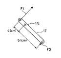
支持リンク部材17は、リンク回動軸17cによってハウジング10aに回動可能に設けられる。そして、支持リンク部材17におけるリンク回動軸17cの位置は、例えば、図2に示すように関係で設定される。
The
図2に示すように、支持リンク部材17の一端側のストッパ16には、ベースユニット11から力F1[kg]が加わり、また、支持リンク部材17の他端側には、バネ部材19による引っ張り力F2[kg]が加わる。このような状態において、支持リンク部材17の一端側からリンク回動軸17cまでの距離をa[cm]、その他端側からリンク回動軸17cまでの距離をb[cm]とすると、梃子の原理から、力F1[kg]×a[cm]=引っ張り力F2[kg]×b[cm]…式(1)と、a[cm]>>b[cm]…式(2)が成立する。
As shown in FIG. 2, a force F <b> 1 [kg] is applied from the
よって、式(1)及び式(2)から、力F1[kg]>>引っ張り力F2[kg]となることから、上述したようにリンク回動軸17c(支持リンク部材17の支点)を設定し、その他端側を比較的小さな引っ張り力F2で保持すれば、一旦側に大きな力F1が加えられても、支持リンク部材17は動かなくなる。
Therefore, from Formula (1) and Formula (2), the force F1 [kg] >> the pulling force F2 [kg] is obtained, so the
つまり、支持リンク部材17によってストッパ16を固定した状態とすることができる。そして、リンク回動軸17cを回動中心として支持リンク部材17が回動することで、その一端側に固定されたストッパ16は、スライド溝10bをスライドしてその回動方向に移動するため、ストッパ16の取付位置を調整することができる。
That is, the
また、反射ミラー12は、例えば、板状のミラー、拡大機能を有する曲面(凹面)ミラー等で構成される。そして、反射ミラー12の背面側には、予め定められた回動範囲内で回動するミラー回動軸12aが設けられている。なお、回動範囲は、例えば、車両に対する乗員の目の位置の分布に対応する範囲(アイレンジ)となるように設定されている。即ち、ダッシュボード1に対する反射ミラー装置10の取付位置にずれが生じると、ダッシュボード1に対するベースユニット12の角度もずれてしまい、その結果、回動範囲がアイレンジからずれることになる。
The
反射ミラー12は、ベースユニット11の起立状態おいて、図1中一点鎖線で示す、発光表示源2から出射された表示光の光路L上に進出する。そして、発光表示源2からの表示光の光路LがアイポイントIに向かうように、図示しない角度調整機構によってミラー回動軸12aを回動させることで、反射ミラー12の角度を前記回動範囲内で調整することが可能な構成となっている。
The
次に、上述した反射ミラー装置10におけるベースユニット11の起立動作について説明する。
Next, the standing operation of the
傾倒状態のベースユニット11は、ダッシュボード1の開口部1aを塞いだ状態となっており、この状態で操作スイッチの操作等に応じてモータ14が方向A1に向かってベースユニット11を移動させるために駆動されると、その駆動力はギア群15を介して回動軸13に伝達され、回動軸13が回動されることで、該回動軸13を回動中心としてベースユニット11は方向A1に向かって回動する。その後、ベースユニット11のストッパ片11aがストッパ16に当接すると、モータ14は駆動を停止し、ベースユニット11は起立状態となる。
The tilted
なお、傾倒状態へ動作については、上述した動作と全くの逆の動作を呈するので、その説明は省略する。 In addition, about operation | movement to a tilted state, since the operation | movement completely opposite to the operation | movement mentioned above is exhibited, the description is abbreviate | omitted.
次に、上述した反射ミラー装置10の車両組付時に、組付作業者が行うストッパ16の調整の一例を、図3及び図4の図面を参照して説明する。
Next, an example of adjustment of the
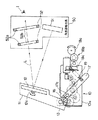
なお、図3において、50は角度調整治具を示し、角度調整治具50は、調整用表示源51と初期角度確認窓52とを備え、調整用表示源51及び初期角度確認窓52は任意の位置に固定している。そして、調整用表示源51は、例えば、蛍光表示管やバックライト付きの液晶表示器が用いられ、図示しないスイッチによって表示のON/OFFが操作可能な構成となっている。
In FIG. 3,
初期角度確認窓52は、その外形を形成する枠部材52aと、その枠部材52aによって囲まれて確認窓の形状に形成される貫通孔52bと、を備える。そして、調整用表示源51から出射した表示光が反射ミラー12で、適切な角度反射した際に、その表示光が完全に通過するように角度調整治具50に固定されている。また、本最良の形態では、2枚の初期角度確認窓52を設けた場合について説明するが、本発明はこれに限定するものではなく、1枚、3枚以上など種々異なる形態とすることができる。
The initial
まず、車両に対する反射ミラー装置10の組み付けが終了すると、組付作業者等は、反射ミラー装置10に対応する設定位置に角度調整治具50を設置する。そして、スイッチのON操作により調整用表示源51に確認用画像を表示させ、この状態で初期角度確認窓52の貫通孔52bを覗き込み、確認画像が貫通孔52bを2つとも完全に通過しているか否かを確認する。
First, when the assembly of the
反射ミラー装置10が適切な位置に組み付けられた場合、図4(A)に示すように、調整用表示源51に表示された確認画像の表示光Gの全ては、2枚の初期角度確認窓52の貫通孔52bを完全に通過して組付作業員のアイポイントIに到達する。よって、2つとも完全に通過している場合、つまり、組付作業員が確認画像が完全な状態で視認できる場合は、反射ミラー装置10が適切な位置に取り付けられていると判定することができるため、確認作業を終了する。
When the
一方、反射ミラー装置10が適切な位置からずれた位置に組み付けられた場合、図4(b)に示すように、調整用表示源51に表示された確認画像の表示光Gは、その一部が枠部材52aによって遮光される。よって、図4(B)中の網掛け箇所で示す欠け部G1の表示光GはアイポイントIに到達しないことから、組付作業者はその一部が欠けた状態の確認画像を視認することになる。よって、その確認画像から反射ミラー装置10が適切な位置からずれた位置に取り付けられていることを認識することができる。
On the other hand, when the reflecting
取付作業者等は、取付位置がずれていることを確認すると、初期角度確認窓52の貫通孔52bを覗き込みながら、調整機構18の調整ダイヤル18aを、確認画像Gの全てが貫通孔52bを通過するように操作する。
When the installation operator confirms that the installation position is shifted, the
また、反射ミラー装置10において、調整ダイヤル18aが操作されて回動すると、その回動量は調整用ギア群18bを介してスライド部材18cに伝達される。そして、スライド部材18cは調整ダイヤル18aの回動方向に応じた方向に、伝達された回動量に応じた分だけスライドする。そして、スライド部材18cがスライドすると、図2に示すバネ部材19による引っ張り力F2とストッパ16に掛かる力F1の釣り合いが崩れるため、支持リンク部材17は引っ張り力F2と力F1が釣り合う方向に、リンク回動軸17cを回動中心として回動する。そして、この支持リンク部材17の回動に伴ってストッパ16も移動し、この移動に応じてベースユニット11も移動する。
Further, in the
このように調整ダイヤル18aの回動操作によって、ベースユニット11のダッシュボード1に対する角度が予め定められたダッシュボードに対する起立角度となるように前記阻止部材の取付位置を調整することができる。その結果、確認用表示源51が表示する確認画像の表示光Gは、図5(A)に示すように、その全てが初期角度確認窓52の貫通孔52bを通過して組付作業員のアイポイントIに到達するようになる。
As described above, the rotation position of the
以上説明したように反射ミラー装置10によれば、ベースユニット11の起立状態における反射ミラー12の回動範囲が、車両における乗員のアイポイントIの分布を示すアイレンジに対応した回動範囲となるように、ストッパ(阻止部材)16の取付位置の調整を可能な構成としたことから、反射ミラー装置10が本来の組付位置からずれた位置に取り付けられても、反射ミラー12の回動範囲はアイレンジに対応した回動範囲に修正することができる。
As described above, according to the
従って、ベースユニット11の起立角度によって反射ミラーの回動範囲を画定して車両のアイレンジをカバーする構成であっても、装置本体の取付位置のずれによる悪影響を排除することができる。また、アイレンジの全てをカバーするために、ベースユニット11の反射ミラー12の回動範囲を大きくする必要もないことから、ベースユニット11、装置本体等の小型化を図ることができる。さらに、ベースユニット11の起立角度の調整を可能とすることで、反射ミラー12の回動範囲も小さくすることができるため、調整時間が短縮され、反射ミラー12の調整作業の効率化を図ることができる。
Accordingly, even if the rotation range of the reflecting mirror is defined by the standing angle of the
また、ベースユニット11とストッパ(阻止部材)16が係止状態に係止した状態で、ベースユニット11に不意な外力が加えられ、その外力がベースユニット11を介してストッパ16に伝達されても、その外力はバネ部材(調整手段)19によって吸収するように構成したことから、ストッパ16に伝達される外力を逃がすことができるため、ストッパ16の外力による破損を防止することができる。
Further, even when the
なお、上述した本最良の形態では、調整手段を支持リンク部材17、調整機構18、バネ部材19で構成する場合について説明したが、本発明はこれに限定するものではなく、ストッパ16をベースユニット11の回動軌跡に応じたスライド溝に沿って駆動力を利用して移動させて固定するなど種々異なる形態とすることができる。
In the above-described best mode, the case where the adjusting means is constituted by the
また、上述した本最良の形態では、反射ミラー12によってダッシュボード1内の発光表示源2が出射した表示光を直接アイポイントIに向けて反射させる場合について説明したが、反射ミラー12と発光表示源2との間に、1又は複数の反射ミラーを介在させる形態とすることもできる。
In the above-described best mode, the case where the display light emitted from the light emitting display source 2 in the dashboard 1 is directly reflected toward the eye point I by the reflecting
1 ダッシュボード
2 発光表示源
10 反射ミラー装置
11 ベースユニット
12 反射ミラー
16 ストッパ
17 支持リンク部材
18 調整機構
19 バネ部材
DESCRIPTION OF SYMBOLS 1 Dashboard 2 Light
Claims (3)
前記ベースユニットが前記起立状態となったときに当該ベースユニットの起立動作を阻止する阻止部材と、
前記ベースユニットの起立状態における前記反射ミラーの前記回動範囲が、前記車両のアイレンジに対応した回動範囲となるように、前記阻止部材の取付位置を調整する調整手段と、
を備えることを特徴とする反射ミラー装置。 A base unit provided so as to be able to stand and tilt with respect to a dashboard of the vehicle, and a reflection mirror pivotally supported by the base unit so as to be rotatable within a predetermined rotation range. By adjusting the angle of the reflecting mirror in the upright state within the rotation range, the optical path of the display light from the light emitting display unit housed in the dashboard is reflected toward the eyepoint of the vehicle occupant In the reflecting mirror device
A blocking member that prevents the base unit from standing up when the base unit is in the upright state;
Adjusting means for adjusting the attachment position of the blocking member so that the turning range of the reflecting mirror in the standing state of the base unit is a turning range corresponding to the eye range of the vehicle;
A reflection mirror device comprising:
前記調整手段は、前記ベースユニットが前記阻止部材に係止した状態で、前記ベースユニットから前記阻止部材に伝達される外力を吸収するように構成されている
ことを特徴とする請求項1に記載の反射ミラー装置。 The blocking member is configured to be locked with a part of the base unit to block the standing operation,
The said adjustment means is comprised so that the external force transmitted to the said blocking member from the said base unit may be absorbed in the state which the said base unit latched to the said blocking member. Reflection mirror device.
前記反射ミラー装置として請求項1又は2記載の反射ミラー装置を用いる
ことを特徴とする車両用表示装置。 A vehicle display device comprising: a light emitting display source housed in a dashboard of a vehicle; and a reflection mirror device that reflects display light from the light emitting display source toward an eyepoint of an occupant of the vehicle,
The vehicle display device, wherein the reflection mirror device according to claim 1 or 2 is used as the reflection mirror device.
Priority Applications (1)
| Application Number | Priority Date | Filing Date | Title |
|---|---|---|---|
| JP2004112676A JP2005297619A (en) | 2004-04-07 | 2004-04-07 | Reflective mirror device and vehicle display device |
Applications Claiming Priority (1)
| Application Number | Priority Date | Filing Date | Title |
|---|---|---|---|
| JP2004112676A JP2005297619A (en) | 2004-04-07 | 2004-04-07 | Reflective mirror device and vehicle display device |
Publications (1)
| Publication Number | Publication Date |
|---|---|
| JP2005297619A true JP2005297619A (en) | 2005-10-27 |
Family
ID=35329714
Family Applications (1)
| Application Number | Title | Priority Date | Filing Date |
|---|---|---|---|
| JP2004112676A Withdrawn JP2005297619A (en) | 2004-04-07 | 2004-04-07 | Reflective mirror device and vehicle display device |
Country Status (1)
| Country | Link |
|---|---|
| JP (1) | JP2005297619A (en) |
Cited By (3)
| Publication number | Priority date | Publication date | Assignee | Title |
|---|---|---|---|---|
| JP2007302195A (en) * | 2006-05-15 | 2007-11-22 | Calsonic Kansei Corp | Display device for vehicle |
| JP2009160966A (en) * | 2007-12-28 | 2009-07-23 | Mitsubishi Cable Ind Ltd | Vehicle obstacle indicator |
| CN104176256A (en) * | 2014-01-02 | 2014-12-03 | 中国商用飞机有限责任公司北京民用飞机技术研究中心 | Airborne multimedia display system |
-
2004
- 2004-04-07 JP JP2004112676A patent/JP2005297619A/en not_active Withdrawn
Cited By (3)
| Publication number | Priority date | Publication date | Assignee | Title |
|---|---|---|---|---|
| JP2007302195A (en) * | 2006-05-15 | 2007-11-22 | Calsonic Kansei Corp | Display device for vehicle |
| JP2009160966A (en) * | 2007-12-28 | 2009-07-23 | Mitsubishi Cable Ind Ltd | Vehicle obstacle indicator |
| CN104176256A (en) * | 2014-01-02 | 2014-12-03 | 中国商用飞机有限责任公司北京民用飞机技术研究中心 | Airborne multimedia display system |
Similar Documents
| Publication | Publication Date | Title |
|---|---|---|
| JP4336245B2 (en) | Head-up display device | |
| TWI493226B (en) | Head-up projection system | |
| US8885260B2 (en) | Head-up display device | |
| JP4871459B2 (en) | In-vehicle head-up display device | |
| JP6957089B2 (en) | Head-up display device | |
| JP4223942B2 (en) | Head-up display device | |
| JP5146906B2 (en) | Head-up display device | |
| JP2003039981A (en) | Automotive head-up display device | |
| JP4648730B2 (en) | Vehicle display device | |
| EP3521885B1 (en) | Vehicle display device | |
| WO2012131945A1 (en) | Image display device and method for adjusting position for installing same | |
| JP2009126494A (en) | Head-up display device | |
| JP2019077327A (en) | Display device for vehicle and display system for vehicle | |
| JP2009222882A (en) | Head-up display device | |
| JP2005297619A (en) | Reflective mirror device and vehicle display device | |
| JP7554394B2 (en) | Head-up display | |
| JP2009090700A (en) | Rear-view mirror system with display device | |
| JP2022137872A (en) | Display unit for vehicle | |
| JP2006248322A (en) | Vehicle display device | |
| JP2019162903A (en) | Mirror movable mechanism of head-up display device | |
| JP6842312B2 (en) | Display device | |
| WO2012117496A1 (en) | Display device | |
| JP7589638B2 (en) | Vehicle display device | |
| JP2527716Y2 (en) | Vehicle head-up display | |
| JP2019162904A (en) | Mirror support structure of head-up display device |
Legal Events
| Date | Code | Title | Description |
|---|---|---|---|
| A300 | Application deemed to be withdrawn because no request for examination was validly filed |
Free format text: JAPANESE INTERMEDIATE CODE: A300 Effective date: 20070703 |