JP2005297563A - Resin material supplying device - Google Patents
Resin material supplying device Download PDFInfo
- Publication number
- JP2005297563A JP2005297563A JP2005108786A JP2005108786A JP2005297563A JP 2005297563 A JP2005297563 A JP 2005297563A JP 2005108786 A JP2005108786 A JP 2005108786A JP 2005108786 A JP2005108786 A JP 2005108786A JP 2005297563 A JP2005297563 A JP 2005297563A
- Authority
- JP
- Japan
- Prior art keywords
- raw material
- resin
- mixer
- resin raw
- main body
- Prior art date
- Legal status (The legal status is an assumption and is not a legal conclusion. Google has not performed a legal analysis and makes no representation as to the accuracy of the status listed.)
- Granted
Links
Images


Classifications
-
- B—PERFORMING OPERATIONS; TRANSPORTING
- B29—WORKING OF PLASTICS; WORKING OF SUBSTANCES IN A PLASTIC STATE IN GENERAL
- B29C—SHAPING OR JOINING OF PLASTICS; SHAPING OF MATERIAL IN A PLASTIC STATE, NOT OTHERWISE PROVIDED FOR; AFTER-TREATMENT OF THE SHAPED PRODUCTS, e.g. REPAIRING
- B29C31/00—Handling, e.g. feeding of the material to be shaped, storage of plastics material before moulding; Automation, i.e. automated handling lines in plastics processing plants, e.g. using manipulators or robots
- B29C31/04—Feeding of the material to be moulded, e.g. into a mould cavity
-
- B—PERFORMING OPERATIONS; TRANSPORTING
- B29—WORKING OF PLASTICS; WORKING OF SUBSTANCES IN A PLASTIC STATE IN GENERAL
- B29B—PREPARATION OR PRETREATMENT OF THE MATERIAL TO BE SHAPED; MAKING GRANULES OR PREFORMS; RECOVERY OF PLASTICS OR OTHER CONSTITUENTS OF WASTE MATERIAL CONTAINING PLASTICS
- B29B7/00—Mixing; Kneading
- B29B7/02—Mixing; Kneading non-continuous, with mechanical mixing or kneading devices, i.e. batch type
- B29B7/06—Mixing; Kneading non-continuous, with mechanical mixing or kneading devices, i.e. batch type with movable mixing or kneading devices
- B29B7/10—Mixing; Kneading non-continuous, with mechanical mixing or kneading devices, i.e. batch type with movable mixing or kneading devices rotary
- B29B7/18—Mixing; Kneading non-continuous, with mechanical mixing or kneading devices, i.e. batch type with movable mixing or kneading devices rotary with more than one shaft
- B29B7/20—Mixing; Kneading non-continuous, with mechanical mixing or kneading devices, i.e. batch type with movable mixing or kneading devices rotary with more than one shaft with intermeshing devices, e.g. screws
-
- B—PERFORMING OPERATIONS; TRANSPORTING
- B29—WORKING OF PLASTICS; WORKING OF SUBSTANCES IN A PLASTIC STATE IN GENERAL
- B29B—PREPARATION OR PRETREATMENT OF THE MATERIAL TO BE SHAPED; MAKING GRANULES OR PREFORMS; RECOVERY OF PLASTICS OR OTHER CONSTITUENTS OF WASTE MATERIAL CONTAINING PLASTICS
- B29B7/00—Mixing; Kneading
- B29B7/02—Mixing; Kneading non-continuous, with mechanical mixing or kneading devices, i.e. batch type
- B29B7/22—Component parts, details or accessories; Auxiliary operations
- B29B7/26—Component parts, details or accessories; Auxiliary operations for discharging, e.g. doors
-
- B—PERFORMING OPERATIONS; TRANSPORTING
- B29—WORKING OF PLASTICS; WORKING OF SUBSTANCES IN A PLASTIC STATE IN GENERAL
- B29C—SHAPING OR JOINING OF PLASTICS; SHAPING OF MATERIAL IN A PLASTIC STATE, NOT OTHERWISE PROVIDED FOR; AFTER-TREATMENT OF THE SHAPED PRODUCTS, e.g. REPAIRING
- B29C31/00—Handling, e.g. feeding of the material to be shaped, storage of plastics material before moulding; Automation, i.e. automated handling lines in plastics processing plants, e.g. using manipulators or robots
- B29C31/04—Feeding of the material to be moulded, e.g. into a mould cavity
- B29C31/06—Feeding of the material to be moulded, e.g. into a mould cavity in measured doses, e.g. by weighting
- B29C31/061—Feeding of the material to be moulded, e.g. into a mould cavity in measured doses, e.g. by weighting using stationary volumetric measuring chambers
-
- B—PERFORMING OPERATIONS; TRANSPORTING
- B29—WORKING OF PLASTICS; WORKING OF SUBSTANCES IN A PLASTIC STATE IN GENERAL
- B29C—SHAPING OR JOINING OF PLASTICS; SHAPING OF MATERIAL IN A PLASTIC STATE, NOT OTHERWISE PROVIDED FOR; AFTER-TREATMENT OF THE SHAPED PRODUCTS, e.g. REPAIRING
- B29C37/00—Component parts, details, accessories or auxiliary operations, not covered by group B29C33/00 or B29C35/00
- B29C2037/90—Measuring, controlling or regulating
Abstract
Description
本発明は、例えば、射出成形機または押出成形機に異なる種類の樹脂原料を均一に混合して供給するために用いられる樹脂原料供給装置に関する。 The present invention relates to a resin raw material supply apparatus used to uniformly mix and supply different types of resin raw materials to, for example, an injection molding machine or an extrusion molding machine.
所望の色彩を呈する樹脂製品を射出成形などによって製造する場合、素材の樹脂本来の色彩を呈する樹脂ペレットと、所要の顔料を配合した着色済み樹脂ペレットとを、それぞれ所定の配合比により、ほぼ逆円錐形状の混合用ホッパに順次または同時に投入している。そして、係る混合用ホッパ内で層状または不規則に堆積した上記2種類の樹脂原料を攪拌して混合した後、係るホッパの下方に位置する射出成形機などのキャビティ内に圧入して、所定形状の樹脂製品に成形している。 When a resin product exhibiting a desired color is manufactured by injection molding or the like, the resin pellets exhibiting the original color of the material resin and the colored resin pellets blended with the required pigment are almost reversed by a predetermined blending ratio. They are fed sequentially or simultaneously into a conical mixing hopper. Then, after mixing and mixing the two kinds of resin raw materials layered or irregularly in the mixing hopper, the mixture is press-fitted into a cavity of an injection molding machine or the like located below the hopper to obtain a predetermined shape. Molded into resin products.
ところで、前記混合用ホッパ内に2種類のペレットなどの樹脂原料を順次投入した場合、前回の成形に用いた樹脂原料の残部と新たな樹脂原料とが搬送系路内で混在してしまう。係る混在を防ぐため、射出成形機に対し樹脂原料を搬送する搬送系路に、加圧エア供給出段を接続し、係るエアにより前回の樹脂原料を除去する樹脂原料供給装置が提案されている(例えば、特許文献1参照)。
しかし、上記エアの吹き付け方式では、スクリューやホッパなどの容器内に残る樹脂原料を確実に除去し、不用意な混合を防ぐことは、極めて不十分であった。
By the way, when resin raw materials such as two kinds of pellets are sequentially charged into the mixing hopper, the remainder of the resin raw material used in the previous molding and a new resin raw material are mixed in the transport system. In order to prevent such mixing, a resin raw material supply apparatus has been proposed in which a pressurized air supply / outlet stage is connected to a conveyance path for conveying a resin raw material to an injection molding machine, and the previous resin raw material is removed by such air. (For example, refer to Patent Document 1).
However, in the air blowing method described above, it has been extremely insufficient to reliably remove the resin raw material remaining in a container such as a screw or a hopper and prevent inadvertent mixing.
本発明は、前記背景技術における問題点を解決し、異なる種類の樹脂原料を均一に混合ししつ成形機に対し安定して供給できると共に、原料投入部の清掃が容易な樹脂原料供給装置を提供する、ことを課題とする。 The present invention solves the problems in the background art described above, and provides a resin raw material supply device that can stably supply different types of resin raw materials uniformly to a molding machine and can easily clean the raw material charging unit. The issue is to provide.
本発明は、前記課題を解決するため、発明者らによる鋭意研究の結果、異なる種類の樹脂原料を攪拌して混合するミキサ本体に対し、係る樹脂原料を投入する原料投入部を分割可能な構造とする、ことに着想して成されたものである。
即ち、本発明の樹脂原料供給装置(請求項1)は、複数のホッパ内から個々に流れ出る異なる種類の樹脂原料を、それぞれ個別に投入する複数の原料投入部と、上記複数の原料投入部から個別に投入される異なる種類の樹脂原料を攪拌する攪拌羽根を内部(中空部)に有するミキサ本体と、を含み、
上記複数の原料投入部のうち、少なくとも1つは、スクリュウを内蔵する投入部本体と、係る本体に結合され且つ上記スクリュウを駆動するギアを内蔵するギアボックスと、を有すると共に、少なくとも上記投入部本体は、上記スクリュウの位置を基準として、上部体と下部体とに分離可能である、ことを特徴とする。
In order to solve the above problems, the present invention has a structure in which a raw material charging portion for charging a resin raw material can be divided into a mixer body that stirs and mixes different types of resin raw materials as a result of intensive studies by the inventors. And was conceived by the idea.
That is, the resin raw material supply apparatus according to the present invention (Claim 1) includes a plurality of raw material input portions for individually supplying different types of resin raw materials that individually flow out from the plurality of hoppers, and the plurality of raw material input portions. A mixer main body having a stirring blade for stirring different types of resin raw materials to be individually fed inside (hollow part),
At least one of the plurality of raw material charging units has a charging unit main body containing a screw and a gear box containing a gear coupled to the main body and driving the screw, and at least the charging unit. The main body is separable into an upper body and a lower body based on the position of the screw.
また、本発明には、前記ミキサ本体には、前記攪拌羽根の上方に位置し且つ投入される前記異なる種類の樹脂原料の堆積レベルを検知する位置センサが取り付けられている、樹脂原料供給装置(請求項2)も含まれる。
更に、本発明には、前記ミキサ本体は、その側面に内部(中空部)が透視できる開閉可能なドアを有する、樹脂原料供給装置(請求項3)も含まれる。
加えて、本発明には、前記ミキサ本体は、ほぼ四角柱で前記攪拌羽根を有する内部(中空部)と、下方の成形機に送給するほぼ円錐形または角錐形のシュート構造部と、を有している、樹脂原料供給装置(請求項4)も含まれる。
In the present invention, the mixer body is provided with a resin material supply device (position sensor for detecting a deposition level of the different types of resin materials to be input, which is located above the stirring blades). Claim 2) is also included.
Furthermore, the present invention includes a resin raw material supply device (Claim 3) in which the mixer body has an openable and closable door through which the inside (hollow part) can be seen through.
In addition, according to the present invention, the mixer main body includes an interior (hollow part) having a substantially quadrangular prism and the stirring blades, and a substantially conical or pyramidal chute structure part to be fed to a lower molding machine. The resin raw material supply apparatus (Claim 4) is also included.
前記請求項1の樹脂原料供給装置によれば、例えば透明または白色などのモノクロを呈する一方の樹脂原料と、予め顔料により所定の色彩にされた他方の樹脂原料である着色済み樹脂原料と、を所定の配合比により、ミキサ本体内に投入して混合する作業の後で、且つ別の色彩の着色済み樹脂原料を用いる前に、前記原料投入部を上部体と下部体とに分離することで、露出するスクリュウなどに付着した前回の樹脂原料の残り屑を、確実に除去して清掃することができる。このため、複数の前記原料投入部から投入された異なる種類の樹脂原料を、前記攪拌羽根により攪拌し且つ混合することで、均一な混ざり具合で且つ所望の色彩を呈するための複合樹脂原料とすることができる。従って、係る複合樹脂原料を、例えば射出成形機のキャビティ内に供給することにより、所望の色彩を呈する樹脂製品を確実に成形できる。しかも、投入部本体の分解、内部の洗浄または清掃、および再組立により、前回の成型時と異なる種類の原料を、同じ原料投入部を介してミキサ本体に確実に投入できると共に、原料投入部の保守管理も容易となる。
According to the resin raw material supply apparatus of
尚、前記スクリュウは、1つでも一対以上を並列に配置する形態の何れでも良い。また、前記異なる樹脂原料は、単に色彩が異なるだけではなく、各種の特性や、あるいは、粒径や粒形状が異なる組合せも含まれる。また、係る樹脂原料は、例えばペレットとして各ホッパに貯留され、専用の原料投入部によって、ペレットのまま前記ミキサ本体に投入されるほか、樹脂粉末や顔料粉末の形態として、ミキサ本体に投入される場合もある。更に、前記攪拌羽根は、モータなどに連結される回転軸と、係る回転軸から対称且つ放射方向に沿って延びる複数の攪拌翼と、を備えている。加えて、前記ギアボックスも、前記の原料投入部と同様に、上下に分離可能な構造としても良い。 Note that one screw or a pair of screws may be arranged in parallel. The different resin raw materials not only differ in color, but also include various characteristics and combinations having different particle sizes and particle shapes. In addition, the resin raw material is stored in each hopper as pellets, for example, and is put into the mixer main body as a pellet by a dedicated raw material charging unit, and is also charged into the mixer main body in the form of resin powder or pigment powder. In some cases. Furthermore, the stirring blade includes a rotating shaft connected to a motor or the like, and a plurality of stirring blades extending symmetrically from the rotating shaft and extending in the radial direction. In addition, the gear box may have a structure that can be separated into the upper and lower parts, like the raw material charging unit.
前記請求項2の樹脂原料供給装置によれば、ミキサ本体に投入された異なる種類の樹脂原料の堆積したレベルが、前記位置センサにより逐次検出される。このため、上記ミキサ本体に投入された異なる種類の樹脂原料の投入量が最適量に保たれるように、前記ホッパまたは原料供給部に対して制御することで、適正量に堆積した異なる種類の樹脂原料を混合ししつ、ミキサ本体内に貯留することができる。従って、安定した成形作業を継続して行うことが可能となる。
前記請求項3の樹脂原料供給装置によれば、ミキサ本体の前記ドアを介して、当該ミキサ本体の内部(中空部)において異なる樹脂原料の混合状態を視認できると共に、作業ごとの間で、上記ドアを開放して、上記内部(中空部)を攪拌羽根を含めて容易に清掃することができる。従って、所望の色彩を呈する樹脂製品を安定的且つ継続して製造することが可能となる。
According to the resin raw material supply apparatus of the second aspect, the accumulated level of different types of resin raw materials charged into the mixer body is sequentially detected by the position sensor. For this reason, by controlling the hopper or the raw material supply unit so that the input amount of the different types of resin raw materials charged into the mixer body is kept at the optimum amount, The resin raw material can be mixed and stored in the mixer body. Therefore, it is possible to continuously perform a stable molding operation.
According to the resin raw material supply apparatus of the third aspect, the mixing state of different resin raw materials can be visually recognized inside the mixer main body (hollow part) through the door of the mixer main body, and between each operation, By opening the door, the inside (hollow part) including the stirring blade can be easily cleaned. Therefore, it is possible to stably and continuously produce a resin product exhibiting a desired color.
前記請求項4の樹脂原料供給装置によれば、前記ミキサ本体が前記攪拌羽根を内蔵する内部(中空部)をほぼ四角柱とし、その下方にシュート構造部を有しているため、従来のほぼ逆円錐形状を呈するホッパ形のミキサ本体に比べて、容積を可及的に小さくコンパクトにすることができる。この結果、異なる種類の樹脂原料が攪拌により混合される際に、各樹脂原料に生じる静電気を低減できるので、複数の樹脂原料が互いに吸着した団子状の塊となりにくい。従って、異なる樹脂原料を均一に攪拌し且つ混合でき、所望の色彩を呈するための複合樹脂原料として、シュート構造部の下方に位置する射出成形機などに供給することができる。 According to the resin raw material supply apparatus of the fourth aspect, the mixer main body has the inside (hollow portion) in which the stirring blades are incorporated as a substantially quadrangular prism, and has a chute structure portion below it. Compared with a hopper-shaped mixer body having an inverted conical shape, the volume can be made as small and compact as possible. As a result, when different types of resin raw materials are mixed by stirring, static electricity generated in each resin raw material can be reduced, so that a plurality of resin raw materials are unlikely to form a dumpling lump adsorbed to each other. Accordingly, different resin raw materials can be uniformly stirred and mixed, and can be supplied to an injection molding machine or the like located below the chute structure as a composite resin raw material for exhibiting a desired color.
以下において、本発明を実施するための最良の形態について説明する。
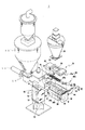
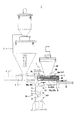
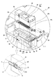
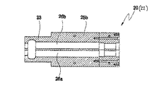
図1は、本発明の樹脂原料供給装置1を示す斜視図、図2は、その分解斜視図、図3は、一部に垂直断面を含む上記装置1の正面(側面)図、図4は、後述する原料投入部20の拡大分解斜視図およびその一部拡大図である。
樹脂原料供給装置1は、図1〜図3に示すように、一対(複数)のホッパ30,30′と、これらから下方に流れ出る異なる種類の樹脂ペレット(樹脂原料:図示せず)を個別に受入る一対(複数)の原料投入部20,20′と、これらから各樹脂ペレットを受け入れて攪拌・混合するミキサ本体10と、を備えている。
予め、小型のホッパ30内には、例えば、予め顔料により所定の色彩にされた着色済み樹脂ペレットが貯留され、大型のホッパ30′には、例えば、樹脂素材本来の透明または白色などのモノクロ色を呈する樹脂ペレットが貯留されている。
In the following, the best mode for carrying out the present invention will be described.
1 is a perspective view showing a resin raw
As shown in FIGS. 1 to 3, the resin raw
In the
ミキサ本体10は、図1〜図3に示すように、全体が四角柱を呈し、且つ四角柱の中空部(内部)を内蔵すると共に、下部にほぼ逆円錐形に縮径するシュート構造部を有し、その正面(側面)には、長方形の開口部を開閉するための透明なドア12が、複数の第5クランプC5により開閉可能に固定されている。係るドア12を介して、中空部内の状態を視認できると共に、当該ドア12を開放することで、次述する攪拌羽根14などに付着した前回の樹脂ペレットの残り屑を清掃して容易に除去することができる。尚、係るミキサ本体10は、下端の水平なプレートが図示しない射出成形機などの上方に固定される。
As shown in FIGS. 1 to 3, the
ミキサ本体10の中空部には、ここに投入される異なる種類の樹脂ペレットを均一に混合する攪拌羽根14が回転自在に配置されている。係る攪拌羽根14は、図1,図2に示すように、上記中空部のほぼ中間高さに位置する水平な回転軸と、係る回転軸から対称で且つ放射状に延びる2本ずつのアーム(攪拌翼)と、これらアームの先端間に位置する一対の棒(攪拌翼)とからなる。係る攪拌羽根14は、その回転軸に連結され且つ上記ドア12と反対側に取り付けたモータ15により、所要の回転数で回転される。
以上のように、ミキサ本体10は、四角柱の中空部に攪拌羽根14を内蔵し、且つ下部にほぼ逆円錐形に縮径するシュート構造部を有するため、その容積を可及的に小さくコンパクトにすることができる。このため、異なる種類の樹脂原料を攪拌羽根14により攪拌・混合する際に、各樹脂原料に生じる静電気を低減し易くなるので、団子状の塊となりにくい。従って、異なる樹脂原料を均一に攪拌し且つ混合して、所望の色彩を呈するための複合樹脂原料を確実に供給することが可能となる。
In the hollow portion of the mixer
As described above, the
図3の正面(側面)図で示すように、ミキサ本体10の中空部において、前記攪拌羽根14の直上の位置に、位置(レベル検出)センサSが取り付けられている。係る位置センサSは、ミキサ本体10の中空部に投入される異なる種類の樹脂ペレットの堆積レベルを検出し、適正な堆積量を保つために用いられる。尚、係る位置センサSには、投光部のみ、または投光部と受光部とからなる光センサ、近接センサ、静電容量センサ、あるいはトルクセンサなどが用いられる。
例えば、上記位置センサSに光センサを用いた場合、投光部からの光がミキサ本体10の中空部を貫通して反対側の受光部に達し、前記樹脂ペレットの堆積量が不足していることを検出した際には、後述するホッパ30,30′下端の開閉ドアに対し、異なる種類の樹脂ペレットの一方または双方を流下させるべく、開放の指令を出すように、図示しない制御部が作動する。尚、上述したように、樹脂ペレットが不足した場合には、ミキサ本体10の上面に取り付けた回転非常灯Lを併せて作動させるようにしても良い。
As shown in the front (side) view of FIG. 3, a position (level detection) sensor S is attached to a position directly above the stirring
For example, when an optical sensor is used for the position sensor S, the light from the light projecting part passes through the hollow part of the
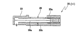
更に、図1〜図4に示すように、原料投入部20,20′は、前者で例示すると、ミキサ本体10の側壁から水平で且つ平行に取り付けた左右一対のガイドGによりスライド可能に案内される投入部本体22と、係る投入部本体22に内蔵される左右一対のシリンダ26a,26bおよびスクリュウ27a,27bと、上記投入部本体22の先端側に結合されるギアボックス40と、を備えている。
尚、ホッパ30′側の原料投入部20′も、上記と同様な一対のシリンダやスクリュなどを有し、その先端に上記と同様なギアボックス40′を設けている。
上記投入部本体22は、スクリュウ27a,27bの軸心の高さにおいて、上部体25aと、下部体25bとに分離可能とされ、左右一対ずつの第2クランプC2と第2受けリングD2との係止により、上・下部体25a,25bを再結合可能としている。
Furthermore, as shown in FIGS. 1 to 4, the raw
The raw
The insertion portion
前記一対のガイドGは、公知の送り機構を介して、原料投入部20をミキサ本体10寄りに接近させたり、あるいは、ミキサ本体10から離れるようにスライドさせる。
図2,図4に示すように、投入部本体22の上部体25aは、その上面の中央に設けた角形孔29に、ホッパ30の下端に開口する流出口(図示せず)が連通している。係るホッパ30の下端のプレートに設けた第3クランプC3が、上記孔29の両側に位置する一対の受けリングD3に係止することにより、当該ホッパ30は、原料投入部20の上に垂直姿勢で且つ着脱自在に取り付けられる。
尚、ホッパ30,30′の上記流出口には、樹脂ペレットの供給を制御する図示しないドアが配置され、前記位置センサSにより、その開閉の制御がされる。
The pair of guides G slide the raw
As shown in FIGS. 2 and 4, the
A door (not shown) for controlling the supply of the resin pellets is disposed at the outlet of the
図5は、投入部本体22の水平断面図、図6は、スクリュウ27a,27bを除いた投入部本体22の垂直断面図、図7はその水平断面図、図8は、図6と異なる位置における投入部本体22の垂直断面図である。
図4〜図8に示すように、原料投入部20には、ほぼ円柱形である左右一対のシリンダ26a,26bが断面ほぼ繭形に隣接して形成され、各シリンダ26a,26b内にスクリュウ27a,27bが回転自在且つ個別に配置されている。係るスクリュウ27a,27bは、互いにほぼ噛み合い式の構造となる螺旋形のネジ山を有し、前記ホッパ30から上部体25aの角形孔29を介して、流下する着色済み樹脂ペレットを、例えば、同じ方向に回転する両者のネジ山同士によって、順次前記ミキサ本体10寄りの基端部23に押し込みつつ移動させる。
尚、図8中の垂直の矢印は、樹脂原料が、基端部23における底面の開口孔から、ミキサ本体10の中空部に投入される位置を示す。
FIG. 5 is a horizontal sectional view of the charging unit
As shown in FIGS. 4 to 8, the raw
Note that the vertical arrows in FIG. 8 indicate the positions at which the resin raw material is introduced into the hollow portion of the
図1,図3,図4に示すように、投入部本体22の基端部23は、ミキサ本体10の右側壁(側面)の上端部に形成された角孔に挿入可能とされ、係る基端部23の底面に位置する下向きの開口孔から、スクリュウ27a,27bにより押し出された着色済み樹脂ペレットを、ミキサ本体10の中空部に投入する。
図1,図2,図4に示すように、原料投入部20における下部体25bの先端側には、スクリュウ27a,27bの各回転軸を回転させる複数のギアを内蔵するギアボックス40が結合されている。係るギアボックス40の上方には、丁番を介して、ギアキャップ44が開閉自在に取り付けられる。係るギアキャップ44は、その側面に設けた第4クランプC4を、ギアボックス40の側面に設けた受けリングD4に係止することで、上記複数のギアを両者の内部に密閉している。
As shown in FIGS. 1, 3, and 4, the
As shown in FIGS. 1, 2, and 4, a
図4中の白抜きの矢印の下方に拡大して示すように、投入部本体22の下部体25bにおける基端部23寄りの両側面には、一対の第1クランプC1が取り付けられている。係る第1クランプC1は、下部体25bの側面に固定したベースにピンh1を介して回転可能に支持したレバーRと、当該レバーRの中間にピンh2を介して取り付けたチャンネル形のクランプEと、を有する。
図3に示すように、左右一対のガイドGを介して、原料投入部20をミキサ本体10寄りにスライドさせ、投入部本体22の基端部23をミキサ本体10の中空部内の上方に挿入する。係る状態で、図4の下方に示すように、上記第1クランプC1のレバーRをミキサ本体10寄りに回し、上記クランプEをミキサ本体10の側面に設けた第1受けリングD1に係止した後、レバーRを上記と逆向きに回す。
この結果、原料投入部20は、ミキサ本体10の側面に固定されるため、投入部本体22のシリンダ26a,26b内から、着色済み樹脂ペレットを、ミキサ本体10の中空部内に確実に投入することができる。
A pair of first clamps C <b> 1 are attached to both side surfaces of the
As shown in FIG. 3, the raw
As a result, since the raw
尚、第2〜第5クランプC2〜C5も、前記第1クランプC1と同じ構造であり、第2〜第5受けリングD2〜D5も、前記第1受けリングD1と同じ構造である。また、図3に示すように、ホッパ30′側の原料投入部20′は、前記ガイドGを介することなく、ミキサ本体10の側面に直に固定されているが、前記原料投入部20のように、左右一対のガイドGを介して、ミキサ本体10の側面に対し、接近および離脱可能にスライドするようにしても良い。更に、原料投入部20′も、前記投入部本体22と同様に、上部体と下部体とに分離可能とする構造としても良い。
The second to fifth clamps C2 to C5 have the same structure as the first clamp C1, and the second to fifth receiving rings D2 to D5 have the same structure as the first receiving ring D1. Further, as shown in FIG. 3, the raw
ここで、前述した本発明の樹脂原料供給装置1の使用方法について説明する。
図1の状態で、予め、右側のホッパ30内には、例えば、顔料により所定の色彩にされた着色済み樹脂ペレットを貯留し、左側のホッパ30′には、例えば、樹脂素材本来の透明または白色などのモノクロ色を呈する樹脂ペレットを貯留しておく。また、樹脂原料供給装置1のミキサ本体10の下方には、図示しない射出成形機または押出成形機が配置されている。また、所望の色彩を呈する樹脂製品を成形するため、ホッパ30′内の白色の樹脂ペレットとホッパ30内の着色済み樹脂ペレットとを、例えば、10:1の配合割合とする。
先ず、図1の状態で、左側のホッパ30′の下端におけるドア(図示せず)を開放し、白色の樹脂ペレットを原料投入部20′内の一対のシリンダとスクリュウ(何れも図示せず)との間に流下させる。ギアボックス40′内のモータおよびギア(何れも図示せず)により、上記白色の樹脂ペレットを、順次ミキサ本体10寄りに送り、且つ当該ミキサ本体10の中空部内に連続して投入する。
Here, the usage method of the resin raw
In the state shown in FIG. 1, in the
First, in the state of FIG. 1, the door (not shown) at the lower end of the
この間において、左右一対のガイドGを介して、右側の原料投入部20をミキサ本体10寄りにスライドさせ、図3に示すように、投入部本体22の基端部23を、ミキサ本体10の側壁の前記角孔を貫通させて、当該ミキサ本体10の中空部内に移動させる。この状態を保つため、原料投入部20側の第1クランプC1を、ミキサ本体10側の第1受けリングD1に係止する。
係る状態で、右側のホッパ30の下端におけるドア(図示せず)を開放し、当該ホッパ30内に貯留した前記着色済み樹脂ペレットを、原料投入部20内の一対のシリンダ26a,26bと一対のスクリュウ27a,27bとの間に流下させる。モータMおよびギアボックス40内のギアにより、上記着色済み樹脂ペレットを、順次ミキサ本体10寄りに送り、且つ当該ミキサ本体10の中空部内に連続して投入する。この際、着色済み樹脂ペレットは、先に投入されている前記白色の樹脂ペレットの10%の配合割合で、ミキサ本体10の中空部に堆積する。
During this time, the raw
In this state, a door (not shown) at the lower end of the
更に、ミキサ本体10の中空部に不規則(ランダム)に混合しつつ堆積した前記白色の樹脂ペレットと着色済み樹脂ペレットとは、図1,図2に示すように、後方のモータ15によって回転する攪拌羽根14により、攪拌されつつ混合される。この際、ミキサ本体10の中空部は、四角柱の小さな容積で済むため、上記2種類の樹脂ペレットのうち、複数個が静電気を帯びて互いに吸着して団子状の塊になる事態を低減できるため、これらを均一に攪拌して混合することができる。
この結果、上記2種類の樹脂ペレットは、当初の不規則な混ざり状態から比較的均一な混ざり状態となる。係る均一な混ざり状態となった上記2種類の樹脂ペレット(複合樹脂原料)は、ミキサ本体10の下部におけるほぼ円錐形を呈するシュート構造部の中空部から、その下方に配置されている図示しない射出成形機または押出成形機に供給される。これにより、射出成形機などの内部で、均一な混合状態で加熱・溶融された後に、所定のキャビティに圧入されるため、所望の色彩を呈する樹脂製品を確実に且つ安定して成形することが可能となる。
Further, the white resin pellets and the colored resin pellets deposited while being mixed irregularly (randomly) in the hollow portion of the
As a result, the two types of resin pellets are changed from a first irregular mixed state to a relatively uniform mixed state. The two types of resin pellets (composite resin raw materials) that are in a uniformly mixed state are injected from a hollow portion of a chute structure portion having a substantially conical shape in the lower part of the
また、ミキサ本体10の中空部に堆積する前記白色の樹脂ペレットと着色済み樹脂ペレットとの堆積レベルが順次低下すると、前記攪拌羽根14の直上の位置に取り付けられ位置センサSが作動する。例えば、係る位置センサSが投光部と受光部とからなる光センサである場合、上記堆積レベルの低下により、投光部からの光がミキサ本体10の中空部を貫通して受光部に達し、前記2種類の樹脂ペレットの堆積(供給)量が不足していることを検出する。これに応じて、図示しない制御部が、前記ホッパ30,30′下端の開閉ドアに対し、各樹脂ペレットの一方または双方を投入するように、開放するように指令を出す。このため、ミキサ本体10の中空部には、前記2種類の樹脂ペレットが適正量で保たれる。
尚、図3に示すように、樹脂ペレットが不足した場合には、ミキサ本体10の上面に取り付けた回転非常灯Lを併せて作動させするようにしても良い。
Further, when the deposition level of the white resin pellets and the colored resin pellets deposited in the hollow portion of the mixer
As shown in FIG. 3, when the resin pellet is insufficient, the rotating emergency light L attached to the upper surface of the
更に、所望の色彩を呈する樹脂製品の成形が終了した際には、図2に示すように、第3受け部D3から第3クランプC3を外してホッパ30を取り外す。次いで、第2受け部D2から第2クランプC2を外して、原料投入部20の投入部本体22から、その上部体25aを取り外す。この結果、投入部本体22の下部体25bと共に、シリンダ26a,26bの下半部やスクリュウ27a,27bが露出する。また、取り外された上部体25aでは、シリンダ26a,26bの上半部が露出する。
次に、第4受けリングD4から第4クランプC4を外して、ギアキャップ44を旋回すると、ギアボックス40が開放され、内部のギア類が露出する。係る状態で、図6〜図8に示すように、スクリュウ27a,27bを取り出す。
Further, when the molding of the resin product exhibiting a desired color is completed, the third clamp C3 is removed from the third receiving portion D3 and the
Next, when the fourth clamp C4 is removed from the fourth receiving ring D4 and the
この結果、上部体25aや下部体25bにおけるシリンダ26a,26bの内面、あるいは、スクリュウ27a,27bの表面に付着している前回の着色済み樹脂ペレットまたはその破片を、確実に除去し且つ洗浄することが容易に行える。また、ギアボックス40内のギア類のメンテナンスも容易に行うことができる。
更に、前記と逆の手順および操作によって、シリンダ26a,26b内にスクリュウ27a,27bを挿入し、ギアキャップ44を逆に旋回してギアボックス40を閉鎖し、上部体25aを下部体25bに固定して、原料投入部20を再度組み立てる。そして、係る原料投入部20の上部体25aの上方に、前記と異なる彩色の顔料を含む着色済み樹脂ペレット(樹脂原料)を別途に貯留させたホッパ30を固定する。これにより、前記同様に樹脂原料供給装置1を操作することで、前回と異なる色彩の樹脂製品を確実且つ安定して成形することができる。
しかも、原料投入部20の前記分解、清掃、洗浄、および再組立が、容易且つ迅速に行えるため、成形効率も高めることが可能となる。
As a result, the previous colored resin pellets or fragments thereof attached to the inner surfaces of the
Further, by the reverse procedure and operation as described above, the
In addition, since the disassembly, cleaning, washing, and reassembly of the raw
尚、図1〜図3で、左側の原料投入部20′やギアボックス40′も、前記原料投入部20の投入部本体22やギアボックス40のように、分離または開放可能とすることで、内部のシリンダやスクリュウの清掃や洗浄などを行うことが可能となる。特に、原料投入部20′でも、前回と異なる種類の樹脂ペレットを送給する場合には、有効である。
一方、前記ミキサ本体10のドア12を開放することで、その中空部や前記攪拌羽根14に付着している前回の2種類の樹脂ペレットまたはそれらの破片を、清掃により容易に除去することができる。
In FIG. 1 to FIG. 3, the left raw
On the other hand, by opening the
本発明は、以上において説明した実施の形態に限定されるものではない。
例えば、前記原料投入部20,20′には、左右一対のスクリュウを配置したが、1つのスクリュウを有する原料投入部としても良い。
また、前記2種類の樹脂ペレットは、白色などのモノクロと着色済みの樹脂ペレットとを用いたが、互いに別の着色済みの2種類のの樹脂ペレットとしたり、粒径や特性が異なる2種類の樹脂ペレットとしても良い。あるいは、係る2種類の樹脂ペレットの一方を、顔料粉末やFRPなどの繊維片などとしても良い。
更に、本発明の樹脂原料供給装置は、前記形態に限らず、ミキサ本体10に対し、3つ以上の原料投入部およびホッパを取り付ける形態としても良い。
あるいは、1つの原料投入部は、1つのシリンダとスクリュウとを内蔵する形態や、3つ以上のシリンダとスクリュウとを内蔵する形態としても良い。
上記のほか、本発明は、その趣旨を逸脱しない範囲で適宜変更可能である。
The present invention is not limited to the embodiment described above.
For example, although a pair of left and right screws are arranged in the raw
In addition, the two types of resin pellets are white and other monochrome and colored resin pellets. However, the two types of resin pellets are two types of colored resin pellets that are different from each other. It is good also as a resin pellet. Alternatively, one of the two types of resin pellets may be a fiber piece such as pigment powder or FRP.
Furthermore, the resin raw material supply apparatus of this invention is not restricted to the said form, It is good also as a form which attaches three or more raw material injection | throwing-in parts and a hopper with respect to the mixer
Alternatively, one raw material charging unit may have a form in which one cylinder and a screw are incorporated, or a form in which three or more cylinders and a screw are incorporated.
In addition to the above, the present invention can be modified as appropriate without departing from the spirit of the present invention.
1…………………樹脂原料供給装置
10………………ミキサ本体
12………………ドア
14………………攪拌羽根
20,20′……原料投入部
22………………投入部本体
25a……………上部体
25b……………下部体
26a,26b…シリンダ
27a,27b…スクリュウ
30,30′……ホッパ
40………………ギアボックス
S…………………位置センサ
1 ………………………………………………………………………………………………………………………………………………………………. …………
Claims (4)
上記複数の原料投入部から個別に投入される異なる種類の樹脂原料を攪拌する攪拌羽根を内部に有するミキサ本体と、を含み、
上記複数の原料投入部のうち、少なくとも1つは、スクリュウを内蔵する投入部本体と、係る本体に結合され且つ上記スクリュウを駆動するギアを内蔵するギアボックスと、を有すると共に、少なくとも上記投入部本体は、上記スクリュウの位置を基準として、上部体と下部体とに分離可能である、
ことを特徴とする樹脂原料供給装置。 A plurality of raw material input sections for individually supplying different types of resin raw materials that individually flow out of a plurality of hoppers;
A mixer body having stirring blades for stirring different types of resin raw materials individually fed from the plurality of raw material charging portions, and
At least one of the plurality of raw material charging units has a charging unit main body containing a screw and a gear box containing a gear coupled to the main body and driving the screw, and at least the charging unit. The main body can be separated into an upper body and a lower body based on the position of the screw.
The resin raw material supply apparatus characterized by the above-mentioned.
ことを特徴とする請求項1に記載の樹脂原料供給装置。 The mixer body is provided with a position sensor that is located above the stirring blade and detects the accumulation level of the different types of resin raw materials to be charged.
The resin raw material supply apparatus according to claim 1.
ことを特徴とする請求項1または2に記載の樹脂原料供給装置。 The mixer body has an openable and closable door on the side surface of which the inside can be seen through,
The resin raw material supply apparatus according to claim 1 or 2.
ことを特徴とする請求項1乃至3の何れか一項に記載の樹脂原料供給装置。
The mixer body has a substantially rectangular parallelepiped interior having the stirring blades, and a substantially conical or pyramidal chute structure that is fed to a lower molding machine.
The resin raw material supply apparatus according to any one of claims 1 to 3.
Applications Claiming Priority (1)
| Application Number | Priority Date | Filing Date | Title |
|---|---|---|---|
| KR1020040023290A KR100543095B1 (en) | 2004-04-06 | 2004-04-06 | Meterial feeder |
Publications (2)
| Publication Number | Publication Date |
|---|---|
| JP2005297563A true JP2005297563A (en) | 2005-10-27 |
| JP4589165B2 JP4589165B2 (en) | 2010-12-01 |
Family
ID=35329673
Family Applications (1)
| Application Number | Title | Priority Date | Filing Date |
|---|---|---|---|
| JP2005108786A Expired - Fee Related JP4589165B2 (en) | 2004-04-06 | 2005-04-05 | Resin raw material supply equipment |
Country Status (2)
| Country | Link |
|---|---|
| JP (1) | JP4589165B2 (en) |
| KR (1) | KR100543095B1 (en) |
Cited By (9)
| Publication number | Priority date | Publication date | Assignee | Title |
|---|---|---|---|---|
| WO2009014089A1 (en) * | 2007-07-26 | 2009-01-29 | Sumitomo Heavy Industries, Ltd. | Material supply device for molding machine |
| JP2009028997A (en) * | 2007-07-26 | 2009-02-12 | Sumitomo Heavy Ind Ltd | Material feeding apparatus of molding machine |
| JP2009028998A (en) * | 2007-07-26 | 2009-02-12 | Sumitomo Heavy Ind Ltd | Material feeding device of molding machine |
| TWI465382B (en) * | 2009-08-06 | 2014-12-21 | Karl-Heinz Tetzlaff | Conveyor unit for feeding biomass into a pressure container |
| CN105922469A (en) * | 2016-04-28 | 2016-09-07 | 芜湖顺成电子有限公司 | Stirring and feeding device of low-smoke and halogen-free sheathing material |
| JP2018099778A (en) * | 2016-12-19 | 2018-06-28 | 株式会社名機製作所 | Material supplying method of plasticizing device, and plasticizing device |
| CN108556174A (en) * | 2018-05-22 | 2018-09-21 | 玉环汉新机械科技有限公司 | A kind of injection mold device |
| CN109910193A (en) * | 2019-04-04 | 2019-06-21 | 王涛 | A kind of automation plastic master batch process units |
| CN112476027A (en) * | 2020-11-24 | 2021-03-12 | 涟源市湘源机电有限公司 | Electromechanical device convenient to installation maintenance |
Families Citing this family (5)
| Publication number | Priority date | Publication date | Assignee | Title |
|---|---|---|---|---|
| KR200448111Y1 (en) | 2008-05-30 | 2010-03-18 | (주)아모레퍼시픽 | Extrusion device cosmetic formulations having structure of the separation with easy capacity changes and clean |
| JP6088728B2 (en) * | 2011-09-27 | 2017-03-01 | 株式会社松井製作所 | Powder material supply device and powder material blending and supplying device provided with the same |
| KR102083678B1 (en) * | 2018-04-19 | 2020-03-02 | 김천곤 | Fixed quantitative supply apparatus for raw material |
| KR102424393B1 (en) * | 2020-10-13 | 2022-07-25 | 주식회사 에스에프에이 | Washing rice supplying system |
| KR102424394B1 (en) * | 2020-10-16 | 2022-07-25 | 주식회사 에스에프에이 | Washing rice supplying system |
Citations (6)
| Publication number | Priority date | Publication date | Assignee | Title |
|---|---|---|---|---|
| JPS49102066U (en) * | 1972-12-27 | 1974-09-03 | ||
| JPS5924305U (en) * | 1982-08-06 | 1984-02-15 | 住友重機械工業株式会社 | Powder/granular material supply/exchange device |
| JPS5929204U (en) * | 1982-08-16 | 1984-02-23 | 三菱樹脂株式会社 | Co-directional twin-screw kneading machine for thermoplastic resin |
| JPH04175119A (en) * | 1990-11-09 | 1992-06-23 | Nissei Plastics Ind Co | Exchange device for material |
| JPH09290438A (en) * | 1996-04-25 | 1997-11-11 | Nishikawa Kasei Co Ltd | Resin raw material supply device for injection molding machine |
| JP2000210938A (en) * | 1999-01-27 | 2000-08-02 | Shingo Hishida | Automatically measuring and feeding apparatus for synthetic resin molding material |
-
2004
- 2004-04-06 KR KR1020040023290A patent/KR100543095B1/en active IP Right Grant
-
2005
- 2005-04-05 JP JP2005108786A patent/JP4589165B2/en not_active Expired - Fee Related
Patent Citations (6)
| Publication number | Priority date | Publication date | Assignee | Title |
|---|---|---|---|---|
| JPS49102066U (en) * | 1972-12-27 | 1974-09-03 | ||
| JPS5924305U (en) * | 1982-08-06 | 1984-02-15 | 住友重機械工業株式会社 | Powder/granular material supply/exchange device |
| JPS5929204U (en) * | 1982-08-16 | 1984-02-23 | 三菱樹脂株式会社 | Co-directional twin-screw kneading machine for thermoplastic resin |
| JPH04175119A (en) * | 1990-11-09 | 1992-06-23 | Nissei Plastics Ind Co | Exchange device for material |
| JPH09290438A (en) * | 1996-04-25 | 1997-11-11 | Nishikawa Kasei Co Ltd | Resin raw material supply device for injection molding machine |
| JP2000210938A (en) * | 1999-01-27 | 2000-08-02 | Shingo Hishida | Automatically measuring and feeding apparatus for synthetic resin molding material |
Cited By (11)
| Publication number | Priority date | Publication date | Assignee | Title |
|---|---|---|---|---|
| WO2009014089A1 (en) * | 2007-07-26 | 2009-01-29 | Sumitomo Heavy Industries, Ltd. | Material supply device for molding machine |
| JP2009028997A (en) * | 2007-07-26 | 2009-02-12 | Sumitomo Heavy Ind Ltd | Material feeding apparatus of molding machine |
| JP2009028998A (en) * | 2007-07-26 | 2009-02-12 | Sumitomo Heavy Ind Ltd | Material feeding device of molding machine |
| JP4704397B2 (en) * | 2007-07-26 | 2011-06-15 | 住友重機械工業株式会社 | Material feeder for molding machine |
| TWI465382B (en) * | 2009-08-06 | 2014-12-21 | Karl-Heinz Tetzlaff | Conveyor unit for feeding biomass into a pressure container |
| CN105922469A (en) * | 2016-04-28 | 2016-09-07 | 芜湖顺成电子有限公司 | Stirring and feeding device of low-smoke and halogen-free sheathing material |
| JP2018099778A (en) * | 2016-12-19 | 2018-06-28 | 株式会社名機製作所 | Material supplying method of plasticizing device, and plasticizing device |
| CN108556174A (en) * | 2018-05-22 | 2018-09-21 | 玉环汉新机械科技有限公司 | A kind of injection mold device |
| CN109910193A (en) * | 2019-04-04 | 2019-06-21 | 王涛 | A kind of automation plastic master batch process units |
| CN109910193B (en) * | 2019-04-04 | 2020-12-22 | 青岛利德液袋有限公司 | Automatic change plastics master batch apparatus for producing |
| CN112476027A (en) * | 2020-11-24 | 2021-03-12 | 涟源市湘源机电有限公司 | Electromechanical device convenient to installation maintenance |
Also Published As
| Publication number | Publication date |
|---|---|
| KR100543095B1 (en) | 2006-01-20 |
| KR20050098067A (en) | 2005-10-11 |
| JP4589165B2 (en) | 2010-12-01 |
Similar Documents
| Publication | Publication Date | Title |
|---|---|---|
| JP4589165B2 (en) | Resin raw material supply equipment | |
| US4560281A (en) | Foundry apparatus for mixing sand with binder | |
| JP6986550B2 (en) | Equipment and Methods for Producing Colored and Uncolored Plastic Melts | |
| CN207899359U (en) | A kind of blender for producing high light-fast Polypropylene | |
| CN208323874U (en) | A kind of vertical mixer | |
| CN207789408U (en) | Cycle mixing device for plastic grains | |
| CN211518128U (en) | Raw material premixing device for thermoplastic plastic product processing | |
| KR100875501B1 (en) | Material mixing/feeding apparatus | |
| KR102178571B1 (en) | Mixer having structure for inner maintenance and cleaning | |
| CN107599200A (en) | A kind of polybag processing batch mixer | |
| CN203680575U (en) | Stirring device for mixing plastic particles and colorants | |
| CN211216225U (en) | Be used for coloured plastic agitating unit | |
| US3979107A (en) | Method of and apparatus for the admixing of a pigment color in a dosaged manner into a plastics material granulate | |
| CN112339240A (en) | Gradient screw extrusion mechanism | |
| US3591145A (en) | Method for continuously mixing powders and oils | |
| US6050721A (en) | Mixing machine for plasticizable compounds | |
| JP2010046605A (en) | Granular material mixing apparatus | |
| JP2007168210A (en) | Molding material supplying apparatus of injection molding machine | |
| CN209173816U (en) | A kind of multiple-rotor mixer for the stirring of PET particle | |
| KR101923159B1 (en) | Material mixer for injection molding | |
| CN209224512U (en) | A kind of novel barrel | |
| KR200372456Y1 (en) | Apparatus for coloring composition and supply of pigment | |
| CN207204008U (en) | A kind of plastic powders automatic recipe maker | |
| CN216295949U (en) | A compounding device for producing artificial slabstone material | |
| CN219171472U (en) | Injection molding mechanism with multiple injection molding openings |
Legal Events
| Date | Code | Title | Description |
|---|---|---|---|
| A621 | Written request for application examination |
Free format text: JAPANESE INTERMEDIATE CODE: A621 Effective date: 20080407 |
|
| TRDD | Decision of grant or rejection written | ||
| A01 | Written decision to grant a patent or to grant a registration (utility model) |
Free format text: JAPANESE INTERMEDIATE CODE: A01 Effective date: 20100810 |
|
| A01 | Written decision to grant a patent or to grant a registration (utility model) |
Free format text: JAPANESE INTERMEDIATE CODE: A01 |
|
| A61 | First payment of annual fees (during grant procedure) |
Free format text: JAPANESE INTERMEDIATE CODE: A61 Effective date: 20100909 |
|
| R150 | Certificate of patent or registration of utility model |
Free format text: JAPANESE INTERMEDIATE CODE: R150 |
|
| FPAY | Renewal fee payment (event date is renewal date of database) |
Free format text: PAYMENT UNTIL: 20130917 Year of fee payment: 3 |
|
| LAPS | Cancellation because of no payment of annual fees |