JP2005297502A - Inkjet printer - Google Patents
Inkjet printer Download PDFInfo
- Publication number
- JP2005297502A JP2005297502A JP2004121102A JP2004121102A JP2005297502A JP 2005297502 A JP2005297502 A JP 2005297502A JP 2004121102 A JP2004121102 A JP 2004121102A JP 2004121102 A JP2004121102 A JP 2004121102A JP 2005297502 A JP2005297502 A JP 2005297502A
- Authority
- JP
- Japan
- Prior art keywords
- information
- ink
- head
- jet printer
- correction
- Prior art date
- Legal status (The legal status is an assumption and is not a legal conclusion. Google has not performed a legal analysis and makes no representation as to the accuracy of the status listed.)
- Pending
Links
- 238000012937 correction Methods 0.000 claims description 39
- 238000012790 confirmation Methods 0.000 claims description 19
- 230000000704 physical effect Effects 0.000 claims description 17
- 239000007788 liquid Substances 0.000 abstract description 4
- 238000007599 discharging Methods 0.000 abstract 1
- 239000000976 ink Substances 0.000 description 94
- 238000012546 transfer Methods 0.000 description 12
- 230000007613 environmental effect Effects 0.000 description 7
- 238000005259 measurement Methods 0.000 description 5
- 230000008859 change Effects 0.000 description 4
- 238000010586 diagram Methods 0.000 description 4
- 230000006866 deterioration Effects 0.000 description 2
- 230000014509 gene expression Effects 0.000 description 2
- 238000000034 method Methods 0.000 description 2
- 230000008569 process Effects 0.000 description 2
- 230000032258 transport Effects 0.000 description 2
- 230000000007 visual effect Effects 0.000 description 2
- 238000004891 communication Methods 0.000 description 1
- 239000000470 constituent Substances 0.000 description 1
- 230000006870 function Effects 0.000 description 1
- 230000007246 mechanism Effects 0.000 description 1
- 239000002184 metal Substances 0.000 description 1
- 230000001360 synchronised effect Effects 0.000 description 1
Images


Landscapes
- Ink Jet (AREA)
Abstract
Description
この発明は、記録媒体上に吐出されるインク液滴の着弾位置を補正するインクジェットプリンタに関する。 The present invention relates to an ink jet printer that corrects the landing position of ink droplets ejected on a recording medium.
近年、インクジェット記録装置では、記録媒体に記録される画像情報の高画質化が急速に進んでいる。この高画質化では、ヘッドを移動しつつインクの液滴を吐出する際に、液滴の目的とする着弾位置からのずれ補正が行われる。これにより、記録媒体の目的とする位置に、目的とするインクの液滴を、正確に着弾させることが行われる。 In recent years, image quality of image information recorded on a recording medium has been rapidly increasing in inkjet recording apparatuses. In this high image quality, when a droplet of ink is ejected while moving the head, deviation correction from the target landing position of the droplet is performed. Thus, the target ink droplet is accurately landed on the target position of the recording medium.
しかし、インクの液滴の吐出速度および向きは、ヘッドごとあるいはインクの液滴を吐出するヘッド内の各ノズルごとに微妙に異なり、さらにヘッドおよび記録媒体の相対位置も、装置ごとに誤差範囲で異なる。そこで、同一の吐出位置を有すると思われるヘッドでも、インクの液滴の着弾位置には、ばらつきが生じる。このばらつきは、画質劣化につながるので、種々の補正がなされる。 However, the ejection speed and direction of ink droplets differ slightly from head to head or from nozzle to nozzle within a head that ejects ink droplets, and the relative positions of the head and recording medium also vary within an error range from device to device. Different. Therefore, even in a head that seems to have the same ejection position, variations occur in the landing positions of ink droplets. Since this variation leads to image quality deterioration, various corrections are made.
ここで、インクの液滴の着弾位置のばらつきを確認パターンを用いてヘッドごとに予め計測しておき、このデータに基づいて、インクの液滴の吐出位置を変更し、インクの液滴の着弾位置を補正することが行われる(例えば、特許文献1参照)。
しかしながら、上記背景技術によれば、確認パターンによるばらつきの計測は、オペレータによりなされ、煩雑な作業であると共に誤差をも含むものとなる。すなわち、確認パターンの計測では、ドット単位のばらつきを計測する必要があり、目視による計測には基本的に無理があると共に、たとえ読み取り装置により、ばらつきの計測がなされる場合にも、補正データの設定には時間と労力が必要とされる。 However, according to the background art described above, the measurement of variation due to the confirmation pattern is performed by an operator, which is a complicated operation and includes errors. In other words, in the measurement of the confirmation pattern, it is necessary to measure the variation in dot units, which is basically impossible for visual measurement, and even when the variation is measured by the reading device, the correction data Setting takes time and effort.
特に、ヘッドから吐出される液滴に、主液滴および副液滴からなる複数の液滴が混在する場合には、記録媒体上のドットにぼけが生じ、記録媒体上の着弾位置の厳密な特定が困難になる場合が多い。この場合、確認パターンの読み取りは、一層の手間と誤差を含むものとなる。 In particular, when a plurality of droplets composed of main droplets and sub-droplets are mixed in the droplets ejected from the head, the dots on the recording medium are blurred, and the landing position on the recording medium is strictly limited. In many cases, identification is difficult. In this case, the reading of the confirmation pattern includes further labor and error.
これらのことから、ヘッドから吐出される液滴の着弾位置を人手を介さずに適正に補正するインクジェットプリンタをいかに実現するかが重要となる。
この発明は、上述した背景技術による課題を解決するためになされたものであり、ヘッドから吐出される液滴の着弾位置を人手を介さずに適正に補正するインクジェットプリンタを提供することを目的とする。
For these reasons, it is important how to realize an ink jet printer that appropriately corrects the landing position of droplets ejected from the head without human intervention.
The present invention has been made to solve the above-described problems caused by the background art, and an object of the present invention is to provide an ink jet printer that appropriately corrects the landing position of a liquid droplet ejected from a head without human intervention. To do.
上述した課題を解決し、目的を達成するために、請求項1に記載の発明にかかるインクジェットプリンタは、インクの液滴を記録媒体に吐出するヘッドと、前記液滴を前記記録媒体上の画素位置に着弾させるプリント部と、を備えるインクジェットプリンタであって、前記インク、前記ヘッドおよび前記プリント部ごとの、前記液滴の着弾位置を確定させるパラメータの個別数値情報に基づいて、前記着弾位置を推定する推定手段と、前記推定の情報に基づいて、前記着弾位置の補正を行う補正手段と、を備えることを特徴とする。
In order to solve the above-described problem and achieve the object, an ink jet printer according to
この請求項1に記載の発明では、インク、ヘッドおよびプリント部ごとの、液滴の着弾位置を確定させるパラメータの個別数値情報に基づいて、推定手段により、着弾位置を推定し、この推定の情報に基づいて、補正手段により、着弾位置の補正を行う。 According to the first aspect of the present invention, the landing position is estimated by the estimating means based on the individual numerical value information of the parameter for determining the landing position of the droplet for each of the ink, the head, and the print unit, and information on this estimation is obtained. Based on the above, the landing position is corrected by the correcting means.
また、請求項2に記載の発明にかかるインクジェットプリンタは、個別数値情報に、インクジェットプリンタが配設される環境の環境情報を備えることを特徴とする。
この請求項2に記載の発明では、個別数値情報に、温度あるいは湿度等の環境情報を含ませる。
According to a second aspect of the present invention, there is provided an ink jet printer including environmental information of an environment in which the ink jet printer is disposed in the individual numerical value information.
In the second aspect of the invention, the individual numerical information includes environmental information such as temperature or humidity.
また、請求項3に記載の発明にかかるインクジェットプリンタは、前記個別数値情報が、前記インクの物性情報を含むことを特徴とする。
この請求項3に記載の発明では、個別数値情報に、粘度あるいは表面張力等のインクの物性情報を含ませる。
The ink jet printer according to the invention of
In the third aspect of the invention, the individual numerical information includes ink physical property information such as viscosity or surface tension.
また、請求項4に記載の発明にかかるインクジェットプリンタは、前記物性情報が、前記インクのインク種あるいはインク色ごとに設定されることを特徴とする。
この請求項4に記載の発明では、物性情報が、インク種情報あるいはインク色情報のみから設定される。
In addition, the ink jet printer according to the invention of
According to the fourth aspect of the invention, the physical property information is set only from the ink type information or the ink color information.
また、請求項5に記載の発明にかかるインクジェットプリンタは、前記補正手段が、前記ヘッドが移動される主走査方向位置での前記吐出のタイミングを制御して前記補正を行うことを特徴とする。 The ink jet printer according to claim 5 is characterized in that the correction means performs the correction by controlling the ejection timing at a position in the main scanning direction in which the head is moved.
この請求項5に記載の発明では、補正手段は、吐出のタイミングを制御して着弾位置の補正を行う。
また、請求項6に記載の発明にかかるインクジェットプリンタは、前記インクジェットプリンタが、前記ヘッドが移動される主走査方向の特定位置での液滴の吐出により、前記記録媒体上に形成される確認パターンを形成し、前記確認パターンに基づいた前記補正の情報を入力する操作パネルを備えることを特徴とする。
According to the fifth aspect of the present invention, the correction means controls the ejection timing to correct the landing position.
According to a sixth aspect of the present invention, there is provided the ink jet printer according to the sixth aspect, wherein the ink jet printer forms a confirmation pattern formed on the recording medium by ejecting droplets at a specific position in the main scanning direction in which the head is moved. And an operation panel for inputting the correction information based on the confirmation pattern.
この請求項6に記載の発明では、インクジェットプリンタは、操作パネルにより、計算によらず実験的な確認パターンに基づいた補正の情報を入力する。
また、請求項7に記載の発明にかかるインクジェットプリンタは、前記インクジェットプリンタが、前記個別数値情報のパラメータの値に、予め設定される範囲内の異なる値を順次設定するパラメータ生成手段を備えることを特徴とする。
In the invention according to claim 6, the ink jet printer inputs correction information based on an experimental confirmation pattern by the operation panel without calculation.
In addition, the ink jet printer according to the invention of claim 7 is provided with a parameter generating means for sequentially setting different values within a preset range as parameter values of the individual numerical information. Features.
この請求項7に記載の発明では、インクジェットプリンタは、パラメータ生成手段により、個別数値情報のパラメータの値に異なる値を順次設定する。 According to the seventh aspect of the invention, the ink jet printer sequentially sets different values for the parameter values of the individual numerical value information by the parameter generation means.
以上説明したように、請求項1に記載の発明によれば、インク、ヘッドおよびプリント部ごとの、液滴の着弾位置を確定させるパラメータの個別数値情報に基づいて、推定手段により、着弾位置を推定し、この推定の情報に基づいて、補正手段により、着弾位置の補正を行うこととしているので、オペレータが着弾位置の実測および入力を行うことなく、自動的に高精度の補正を行い、良好な画質を維持することができる。 As described above, according to the first aspect of the present invention, the landing position is determined by the estimation unit based on the individual numerical information of the parameters for determining the landing position of the droplet for each ink, head, and print unit. Based on the estimated information, the correction means corrects the landing position. Therefore, the operator automatically corrects the high accuracy without performing actual measurement and input of the landing position. Image quality can be maintained.
請求項2に記載の発明によれば、個別数値情報に、温度あるいは湿度等の環境情報を含ませることとしているので、温度あるいは湿度等の環境変化に応じて個別数値情報を最適なものとすることができる。 According to the second aspect of the present invention, since the individual numerical information includes environmental information such as temperature or humidity, the individual numerical information is optimized according to environmental changes such as temperature or humidity. be able to.
請求項3に記載の発明によれば、個別数値情報に、粘度あるいは表面張力等のインクの物性情報を含ませることとしているので、インクの物性情報に影響された着弾位置の変化を計算することができる。 According to the third aspect of the invention, since the physical property information of the ink such as the viscosity or the surface tension is included in the individual numerical information, the change in the landing position affected by the physical property information of the ink is calculated. Can do.
請求項4に記載の発明によれば、物性情報が、インク種情報あるいはインク色情報のみから設定されることとしているので、インク種あるいはインク色のみの入力情報から物性情報を簡易にしかも短時間で設定できる。
According to the invention described in
請求項5に記載の発明によれば、補正手段は、吐出のタイミングを制御して着弾位置の補正を行うこととしているので、着弾位置を、目的とする画素位置に一致させることができる。 According to the fifth aspect of the present invention, since the correction means controls the ejection timing to correct the landing position, the landing position can be matched with the target pixel position.
請求項6に記載の発明によれば、インクジェットプリンタは、操作パネルにより、計算によらず実験的な確認パターンに基づいた補正の情報を入力することとしているので、手動による補正考慮し、より良好な画質とすることができる。 According to the invention described in claim 6, since the ink jet printer is configured to input correction information based on an experimental confirmation pattern regardless of calculation by the operation panel, it is better considering manual correction. Image quality.
請求項7に記載の発明によれば、パラメータ生成手段により、個別数値情報のパラメータの値に異なる値を順次設定することとしているので、繰り返し行われる目視による画質の判定によりパラメータの値を最適化することができる。 According to the seventh aspect of the present invention, since the parameter generation means sequentially sets different values for the parameter values of the individual numerical information, the parameter values are optimized by repeated visual image quality determination. can do.
以下に添付図面を参照して、この発明にかかるインクジェットプリンタを実施するための最良の形態について説明する。なお、これにより本発明が限定されるものではない。
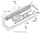
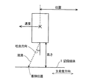
まず、本実施の形態にかかるインクジェットプリンタ10の機械的な構成を図2に示す。図2は、キャリッジ部2を中心とするインクジェットプリンタ10の機械的なプリント部の構成を示す図である。インクジェットプリンタ10のプリント部は、キャリッジ部2、支持棒3、駆動ベルト4、主走査モータ41、ローラ6a、6bおよび記録媒体1を含む。記録媒体1は、画像情報の記録を行う記録紙等からなり、搬送方向である副走査方向に移動される。支持棒3は、副走査方向と直交する主走査方向を向く金属棒で、キャリッジ部2が、主走査方向に移動可能な様に配設される。また、キャリッジ部2は、駆動ベルト4に固定され、ローラ6a,6bに巻かれた駆動ベルト4は、主走査モータ41の駆動により移動される。これにより、キャリッジ部2は、支持棒3上を、主走査方向に移動して記録媒体1上に印画を行う。
The best mode for carrying out an ink jet printer according to the present invention will be described below with reference to the accompanying drawings. Note that the present invention is not limited thereby.
First, FIG. 2 shows a mechanical configuration of the
キャリッジ部2には、ブラックK、シアンC,マゼンタM,イエローY,のインクを含む各カートリッジ1K、1C、1M、1Y、が着脱可能に装着されている。このキャリッジ部2の下端部には、図示しない1K、1C,1M,1Y,ごとのヘッドが存在し、各ヘッドの複数のインク吐出口であるノズルから、キャリッジ部2の下端部に存在する記録媒体1に、インクの吐出が行われる。
The
図3(a)および(b)は、キャリッジ部2に装着された、カートリッジ1K、1C、1M、1Yおよびカートリッジ1Yに接続されるヘッド21dの下端部の拡大図を示す。図3(a)は、キャリッジ部2に装着されたカートリッジ1Yの下端部に存在するヘッド21dを示す。ここで、ヘッド21dは、図3(b)に示す様な、副走査方向に一列に並ぶ複数のノズルを有する。このノズルからは、図3(a)に示すカートリッジ1Y内のインクが同時に吐出され、記録媒体1上に副走査方向に並ぶ一列のインク液滴が記録される。なお、カートリッジ1K、1C、1M、および,図示されない,これらカートリッジに対応するヘッド21a〜cも全く同様の構造を有し、キャリッジ部2の主走査方向に並置される。
FIGS. 3A and 3B are enlarged views of the lower end portion of the
また、キャリッジ部2のヘッド21a〜dおよびカートリッジ1K〜Yは、個別に交換可能となっており、ヘッド21a〜dが劣化した場合あるいはカートリッジ1K〜Y内のインクが枯渇した場合等に交換がなされる。なお、図3および4ではキャリッジ部2にヘッド21a〜dおよびインクを含むカートリッジ1K〜Yが存在するとしているが、カートリッジ1K〜Yをキャリッジ部2の外に固定配置とし、チューブ等によりヘッド21a〜dにインクを供給する様にすることもできる。
In addition, the
ここで、ヘッド21a〜dは、使用回数、使用するインク種あるいは使用期間等から決まる寿命を有する。ヘッド21a〜dは、この寿命に達するとインクの吐出が悪くなり、記録媒体1上に印刷される画像情報が劣化をきたす。オペレータは、この印刷される画像情報の劣化に基づいてヘッド21a〜dの交換を行う。
Here, the
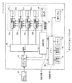
図4は、インクジェットプリンタ10の電気的な構成を示すブロック図である。インクジェットプリンタ10は、インターフェースコントローラ61、画像メモリ64、転送手段71、キャリッジ部2、制御部80、主走査モータ41、副走査モータ42および操作パネル30を含む。なお、インクジェットプリンタ10は、ホストコンピュータ50に接続され、記録する画像情報を取得する。
FIG. 4 is a block diagram showing an electrical configuration of the
インターフェースコントローラ61は、通信回線を介して接続されるホストコンピュータ50から、画像情報を取り込む入力手段をなす。
画像メモリ64は、インターフェースコントローラ61を介して取得される画像情報を、一時的に記憶する。この画像情報は、ホストコンピュータ50の原画像情報の一部分をなし、後述するキャリッジ部2による印画の際の、必要最低限の画像情報を含む。なお、この画像情報は、ブラック、シアン,マゼンタ,イエローの各色ごとに画像情報が形成される。
The
The
キャリッジ部2は、画像メモリ64の画像情報を、記録媒体1に印画する。ここで、キャリッジ部2は、ヘッド21a〜d,ヘッド駆動制御回路23a〜d,駆動回路22およびエンコーダセンサ26を含む。ヘッド21a〜dは、各々、ブラックインク(K)吐出用のヘッド21a、シアンインク(C)吐出用のヘッド21b、マゼンタインク(M)吐出用のヘッド21cおよびイエローインク(Y)吐出用のヘッド21dからなり、図3(a)に示す様に、主走査方向に並置される。また、各ヘッドは、図3(b)に示す様に、副走査方向に一列に並ぶ、例えば512個の、インクを吐出するノズルを有する。
The
ヘッド21a〜dは、カートリッジ1K、1C、1M、1Yのインクを、記録媒体1上にインクの液滴として吐出する。ヘッド21a〜dとして、例えば、シェアモード型のピエゾヘッドが用いられる。
The
駆動回路22は、ヘッド21a〜dを駆動し、インク液滴を吐出させる駆動波形を生成する。この駆動波形は、転送手段71で発生される画像情報のラッチ信号に同期するもので、ラッチ信号ごとに生成される。
The
ヘッド駆動制御回路23a〜dは、画像メモリ64からの画像情報に基づいて、ヘッドa〜dごとにインクの液滴の吐出タイミングが制御される。ヘッド駆動制御回路23a〜dには、ピエゾヘッドを駆動するドライバーがチャネルごとに存在し、駆動回路22からの駆動波形に基づいて、ピエゾヘッドを駆動する。
The head
また、エンコーダセンサ26は、キャリッジ部2上に存在し、例えば、支持棒3の主走査方向に、所定の間隔を持って刻印された黒色のマークを読み取る。これにより、キャリッジ部2の主走査方向の位置を正確に把握し、インクの吐出タイミングを的確なものとする。
The
転送手段71は、画像メモリ64からヘッド駆動制御回路23a〜dに、各ヘッドの複数ノズルからの一回の吐出で記録される部分画像情報を転送する。転送手段71は、タイミング発生回路およびメモリ制御回路を含む。タイミング発生回路は、図示しないホームポジションセンサおよびエンコーダセンサ26の出力から、正確なキャリッジ部2の位置を求め、メモリ制御回路は、この位置情報から、ヘッドごとに必要とされる部分画像情報のアドレスを求める。そして、メモリ制御回路は、この部分画像情報のアドレスを用いて、画像メモリ64からの読み出し、ヘッド駆動制御回路23a〜dへの転送を行う。また、後述する制御部80からの補正テーブルに基づいて、各ヘッドの吐出タイミングを画素単位でずらす機能も有する。
The transfer unit 71 transfers partial image information recorded by one ejection from a plurality of nozzles of each head from the
主走査モータ41は、図2に示す、主走査方向にキャリッジ部2を移動するモータである。また、副走査モータ42は、記録媒体1を副走査方向に搬送する、モータである。
制御部80は、CPU60およびメモリ65を含み、主走査モータ41および副走査モータ42の制御と共に転送手段71を制御し、記録媒体1上へのインクの吐出を制御する。
The
The control unit 80 includes a
操作パネル30は、操作手段をなし、LCDおよびキーボード等で構成され、印刷条件、また後述する個別数値情報および補正テーブル等の入力あるいは表示等が行われる。
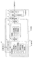
図1は、制御部80の機能的な構成を示す機能ブロック図である。制御部80は、パラメータ生成手段81、推定手段90をなす個別数値情報82、算定手段83、中間情報84、演算手段85および着弾位置情報86、そして、補正手段92をなす補正テーブル生成手段87および補正テーブル88を含む。
The
FIG. 1 is a functional block diagram showing a functional configuration of the control unit 80. The control unit 80 includes parameter generation means 81, individual
推定手段90は、個別数値情報82から算定手段83を用いて、ヘッドから吐出される液滴の着弾位置を計算するための中間情報84を算定し、この中間情報84から着弾位置情報86を演算手段85により求める。
The estimation means 90 uses the calculation means 83 from the individual
個別数値情報82は、インクジェットプリンタ10を構成する各構成要件ごとの、ヘッド21a〜dから吐出される液滴が着弾する位置を確定するパラメータを数値データとしたものである。個別数値情報82には、インク物性情報、ヘッド射出情報、ヘッド取り付け位置情報、ヘッド駆動信号情報、プリンタ走査情報および環境情報等が含まれ、インク、ヘッドおよびプリンタの走査を行う機構部分の各構成要件をなす単体ごとの着弾位置に影響を与える着弾位置のパラメータが含まれる。
The individual
ここで、インク物性情報は、使用されるインクの粘度、表面張力等を含み、ヘッド射出情報は、ヘッド単体のインクの吐出方向を含み、ヘッド取り付け位置情報は、ヘッドをキャリッジ部2に装着する際の取り付け位置情報を含み、ヘッド駆動信号情報は、ヘッドを駆動する際の駆動周期、駆動電圧等を含み、プリンタ走査情報は、主として主走査方向のキャリッジ部2の位置を補正する補正情報を含み、エンコーダセンサ26により計測されるキャリッジ部2の位置情報に補正を加え、より精度の高いものとする。環境情報は、温度および湿度等の情報を含む。
Here, the ink physical property information includes the viscosity, surface tension and the like of the ink used, the head ejection information includes the ink ejection direction of the head alone, and the head mounting position information mounts the head on the
中間情報84は、インク吐出情報、ヘッド位置情報およびヘッド速度情報を含む。図5にこれら情報の物理的意味を図示する。インク吐出情報は、記録媒体1と鉛直をなす方向を基準とした液滴の吐出方向、液滴の速度および液滴の体積を含む。また、ヘッド位置情報は、例えばホームポジションから液滴の吐出が行われる主走査方向のヘッド位置までの正確な位置補正情報およびヘッドの吐出口の記録媒体1からの高さ情報を含む。また、ヘッドの速度情報は、ヘッドが収納されるキャリッジ部2の主走査方向への移動速度情報を含む。なお、これらインク吐出情報、ヘッド位置情報およびヘッド速度情報に含まれる物理量から、液滴の着弾位置は計算により正確に推定され、さらに液滴の体積および記録媒体1への液滴の入射角度からドット形状をも考慮して位置が特定される。
The
一方、中間情報84を構成するインク吐出情報、ヘッド位置情報およびヘッド速度情報は、個別数値情報82から算定手段83により算定される。例えば、インク吐出情報の吐出方向は、個別数値情報82のヘッド単体の場合の液滴射出方向情報を含むヘッド射出情報およびヘッド取り付け位置情報に含まれる取り付け位置情報から、記録媒体1に対する正確な吐出方向が算定される。インク吐出情報の液滴の速度は、インク物性情報の粘度、表面張力等の値、ヘッド駆動信号情報の駆動電圧、駆動周期等の情報に基づいて算定手段83により算定される。
On the other hand, the ink ejection information, the head position information, and the head speed information constituting the
また、ヘッド位置情報は、例えば、プリンタ走査情報に含まれるキャリッジ部2の位置情報およびヘッド取り付け位置情報に含まれる取り付け位置から正確な吐出位置が算定される。また、ヘッド速度情報は、プリンタ走査情報に含まれるキャリッジ部2の主走査方向への移動速度から決定される。
For the head position information, for example, an accurate ejection position is calculated from the position information of the
ここで、算定手段83では、理論的あるいは実験的に、個別数値情報82から中間情報84を算定する関係式が定められる。これら関係式は、インクジェットプリンタ10固有のもであり、同一機種ごとに決定され、また上述した個別数値情報82は、インクジェットプリンタ10ごとに固有の値が設定される。また、インクあるいはヘッドの交換ごとに、インク物性情報、ヘッド射出情報およびヘッド取り付け位置情報は、オペレータにより更新される。
Here, in the calculation means 83, a relational expression for calculating the
なお、個別数値情報82は、温度あるいは湿度等の環境情報を考慮することにより、さらに精密なものとすることができる。特に、個別数値情報82の中で温度あるいは湿度に敏感なパラメータに対しては、温度係数あるいは湿度計数等を情報に含めることにより、精密化される。例えば、インク物性情報の粘度あるいは表面張力等の温度係数情報を含めることにより、インク吐出情報の吐出速度を温度変化があっても精密なものとすることができる。
Note that the individual
着弾位置情報86は、中間情報84から演算手段85により求められる。この着弾位置情報86は、例えば、ヘッド21a〜dごとの主走査方向の特定位置で吐出される液滴の、往路および復路での着弾パターンを計算により導出したもので、図6(b)に示す確認パターンの形状を示す。なお、図6(b)に示すパターン111a〜d,112a〜dは,図6(a)に示す往路でのヘッド21a〜dから吐出される液滴の吐出パターン111a〜dおよび図6(b)に示す復路でのヘッド21a〜dから吐出される液滴の吐出パターン112a〜dである。
The
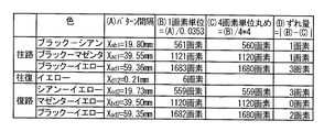
補正テーブル生成手段87は、図6(b)に示すパターン111a〜d,112a〜dの間隔から補正テーブル88を生成する。補正テーブル生成手段87は、図6(b)に示すパターン111a〜d,112a〜dのパターン間隔から、図7に示す様な補正テーブルを生成する。図7に示す補正テーブルでは、図7(A)欄に実測された図6(b)のパターン間隔が示され、図7(B)欄にこのパターン間隔を画素単位に置き換え、図7(C)欄にこの相対距離の標準距離が画素単位で示され、図7(D)欄に標準距離からのずれ量を画素単位で求める。なお、図7の例では、液滴が0.0353mm間隔の画素単位で吐出される場合を例示した。
The correction table generation means 87 generates a correction table 88 from the intervals between the
補正テーブル88は、図7(D)欄に示すずれ量を、転送手段71に転送し、転送手段71はこのずれ量に応じた画素数分だけ、吐出タイミングを変化させる。
パラメータ生成手段81は、操作パネル30からの指示により、新たな個別数値情報82を設定する。この設定では、予め設定される個別数値情報82の各パラメータの上限および下限の値の範囲内で、所定の変化幅を持って操作パネル30からの指示ごとに新たな数値が個別数値情報82に設定される。パラメータ生成手段81は、例えば、ヘッド21a〜dのいずれかを交換した際に、ヘッド取り付け位置情報が適正でなく、印刷された画像情報の劣化が生じる場合等に、個別数値情報82のヘッド取り付け位置情報を最適化するために用いられる。
The correction table 88 transfers the shift amount shown in the column (D) of FIG. 7 to the transfer unit 71, and the transfer unit 71 changes the ejection timing by the number of pixels corresponding to the shift amount.
The
つづいて、制御部80の動作を図8を用いて説明する。図8は、制御部80の動作を示すフローチャートである。まず、制御部80は、操作パネル30から個別数値情報82を入力する(ステップS801)。この個別数値情報82は、工場出荷時、インクの交換時あるいはヘッドの交換時に行われる。工場出荷時には、すべての個別数値情報82が入力され、インクあるいはヘッドの交換時には、交換により変化するもの、例えばインク物性情報あるいはヘッド取り付け位置情報等のパラメータが更新される。
Next, the operation of the control unit 80 will be described with reference to FIG. FIG. 8 is a flowchart showing the operation of the control unit 80. First, the control unit 80 inputs the individual
その後、制御部80は、推定手段90により着弾位置を推定する(ステップS802)。そして、この着弾位置情報から、図7に示す様な補正テーブル88を求め(ステップS803)、図7(D)欄に示すずれ量を転送手段71に送信する。 Thereafter, the control unit 80 estimates the landing position by the estimation unit 90 (step S802). Then, a correction table 88 as shown in FIG. 7 is obtained from the landing position information (step S803), and the deviation amount shown in the column (D) of FIG.
その後、制御部80は、転送手段71が吐出タイミングを図7(D)欄のずれ量だけずらして、順次画像メモリ64の画像情報を印刷する(ステップS804)。そして、オペレータは、記録媒体1上に印刷された画像が良好かどうかを判定し(ステップS805)、良好でない場合には(ステップS805否定)、パラメータ生成手段81を起動し個別数値情報82のパラメータを再設定し(ステップS806)、ステップS802に移行し、再度補正テーブル88の生成および印刷を行う。そして、制御部80は、画像が良好でない場合には、さらにステップS806で異なるパラメータの値を設定して、ステップS802〜804を繰り返す。また、オペレータは、記録媒体1上に印刷された画像が良好である場合には(ステップS805肯定)、個別数値情報82が適切であるとして本処理を終了する。
Thereafter, the control unit 80 sequentially prints the image information in the
上述してきたように、本実施の形態では、ヘッドから吐出される液滴の着弾位置に影響を与える、インク、ヘッドおよびプリンタ本体の単体ごとの個別数値情報82を保存し、個別数値情報82から着弾位置を演算により推定した確認パターン11を求め、この確認パターン11から補正テーブルを作成し、この補正テーブルによりヘッドからのインクの吐出タイミングを制御することとしているので、オペレータが確認パターン11を記録媒体1に印刷し、この確認パターン11の情報を操作パネル30に入力することなしに、高精度の補正テーブルを自動的に生成し、良好な画質を維持することができる。
As described above, according to the present embodiment, the individual
また、本実施の形態では、個別数値情報82のインク物性情報は、操作パネル30から入力されるとしたが、インクを交換する都度に入力されるインク種情報あるいはインクカートリッジの管理番号情報等に連動して入力されるとすることもできる。さらに、個別数値情報82のヘッド射出情報も同様に、ヘッドの管理番号情報等に連動して入力されるとすることもできる。
In the present embodiment, the ink physical property information of the individual
また、本実施の形態では、着弾位置情報86を推定手段90により計算により求めることとしたが、同時に着弾位置情報86を、オペレータによる計測された確認パターン11の実測データに基づいたものとすることもできる。
In the present embodiment, the
1K〜Y カートリッジ
1 記録媒体
2 キャリッジ部
3 支持棒
4 駆動ベルト
6a,6b ローラ
10 インクジェットプリンタ
11 確認パターン
21a〜d ヘッド
22 駆動回路
23a〜d ヘッド駆動制御回路
26 エンコーダセンサ
30 操作パネル
41 主走査モータ
42 副走査モータ
50 ホストコンピュータ
61 インターフェースコントローラ
64 画像メモリ
65 メモリ
71 転送手段
80 制御部
81 パラメータ生成手段
82 個別数値情報
83 算定手段
84 中間情報
85 演算手段
86 着弾位置情報
87 補正テーブル生成手段
88 補正テーブル
90 推定手段
92 補正手段
1K to
Claims (7)
前記液滴を前記記録媒体上の画素位置に着弾させるプリント部と、
を備えるインクジェットプリンタであって、
前記インク、前記ヘッドおよび前記プリント部ごとの、前記液滴の着弾位置を確定させるパラメータの個別数値情報に基づいて、前記着弾位置を推定する推定手段と、
前記推定の情報に基づいて、前記着弾位置の補正を行う補正手段と、
を備えることを特徴とするインクジェットプリンタ。 A head for ejecting ink droplets onto a recording medium;
A print unit for landing the droplet on a pixel position on the recording medium;
An inkjet printer comprising:
Estimating means for estimating the landing position based on individual numerical information of parameters for determining the landing position of the droplet for each of the ink, the head, and the printing unit;
Correction means for correcting the landing position based on the estimated information;
An ink jet printer comprising:
Priority Applications (1)
| Application Number | Priority Date | Filing Date | Title |
|---|---|---|---|
| JP2004121102A JP2005297502A (en) | 2004-04-16 | 2004-04-16 | Inkjet printer |
Applications Claiming Priority (1)
| Application Number | Priority Date | Filing Date | Title |
|---|---|---|---|
| JP2004121102A JP2005297502A (en) | 2004-04-16 | 2004-04-16 | Inkjet printer |
Publications (1)
| Publication Number | Publication Date |
|---|---|
| JP2005297502A true JP2005297502A (en) | 2005-10-27 |
Family
ID=35329623
Family Applications (1)
| Application Number | Title | Priority Date | Filing Date |
|---|---|---|---|
| JP2004121102A Pending JP2005297502A (en) | 2004-04-16 | 2004-04-16 | Inkjet printer |
Country Status (1)
| Country | Link |
|---|---|
| JP (1) | JP2005297502A (en) |
Cited By (3)
| Publication number | Priority date | Publication date | Assignee | Title |
|---|---|---|---|---|
| JP2009226628A (en) * | 2008-03-19 | 2009-10-08 | Seiko Epson Corp | Liquid jetting device |
| US20120225208A1 (en) * | 2009-11-10 | 2012-09-06 | Yasuhiro Tanaka | Fabrication method and fabrication apparatus for solid shaped product |
| CN113910773A (en) * | 2020-07-07 | 2022-01-11 | 细美事有限公司 | Ink impact point correcting device and substrate processing system with same |
-
2004
- 2004-04-16 JP JP2004121102A patent/JP2005297502A/en active Pending
Cited By (3)
| Publication number | Priority date | Publication date | Assignee | Title |
|---|---|---|---|---|
| JP2009226628A (en) * | 2008-03-19 | 2009-10-08 | Seiko Epson Corp | Liquid jetting device |
| US20120225208A1 (en) * | 2009-11-10 | 2012-09-06 | Yasuhiro Tanaka | Fabrication method and fabrication apparatus for solid shaped product |
| CN113910773A (en) * | 2020-07-07 | 2022-01-11 | 细美事有限公司 | Ink impact point correcting device and substrate processing system with same |
Similar Documents
| Publication | Publication Date | Title |
|---|---|---|
| US7645016B2 (en) | Liquid ejection method and liquid ejection apparatus | |
| US20110007112A1 (en) | Recording apparatus and non-transitory computer-readable recording medium storing a recording program | |
| US20090262157A1 (en) | Forming Method of Adjustment Pattern and Liquid Ejection Apparatus | |
| EP3033233B1 (en) | Printhead alignment correction | |
| JP2008229922A (en) | Image forming apparatus, linear encoder contamination detection method, and linear encoder contamination detection image forming method | |
| US7407251B2 (en) | Printing method, computer-readable medium, printing apparatus, printing system, and pattern for correction | |
| US7959253B2 (en) | Printing method, test pattern, method of producing test pattern, and printing apparatus | |
| JP6252240B2 (en) | Printing system, density correction method, and correction necessity determination program | |
| JP4770488B2 (en) | Inkjet printer | |
| JP2005297502A (en) | Inkjet printer | |
| JP2012125974A (en) | Inkjet recording apparatus | |
| US7178895B2 (en) | Correcting method, liquid ejecting apparatus, computer program, computer system, and correction pattern | |
| JP2011046077A (en) | Apparatus and method for ejecting liquid | |
| JP4192629B2 (en) | Printing apparatus, printing method, and printing system | |
| JP4534084B2 (en) | Inkjet printer | |
| JP4449394B2 (en) | Printing apparatus, printing method, and printing system | |
| JP2013184442A (en) | Recording apparatus and control method thereof | |
| JP5553710B2 (en) | Recording apparatus and recording method | |
| JP4720103B2 (en) | Printing apparatus and test pattern manufacturing method | |
| JP4591013B2 (en) | Printing apparatus, printing method, program, and printing system | |
| JP4487608B2 (en) | Control method for liquid ejecting apparatus and liquid ejecting apparatus | |
| JP2005225131A (en) | Printing apparatus, computer program, printing system, printing method, and correction pattern | |
| JP5304587B2 (en) | Liquid ejection apparatus and liquid ejection method | |
| JP2005324359A (en) | Printing apparatus, adjustment pattern, printing method, and printing system | |
| JP4572579B2 (en) | Printing apparatus, test pattern manufacturing method, and printing system |