JP2005297438A - Method and equipment for inspecting print quality - Google Patents
Method and equipment for inspecting print quality Download PDFInfo
- Publication number
- JP2005297438A JP2005297438A JP2004119061A JP2004119061A JP2005297438A JP 2005297438 A JP2005297438 A JP 2005297438A JP 2004119061 A JP2004119061 A JP 2004119061A JP 2004119061 A JP2004119061 A JP 2004119061A JP 2005297438 A JP2005297438 A JP 2005297438A
- Authority
- JP
- Japan
- Prior art keywords
- image
- printing
- difference
- digital data
- pixel
- Prior art date
- Legal status (The legal status is an assumption and is not a legal conclusion. Google has not performed a legal analysis and makes no representation as to the accuracy of the status listed.)
- Withdrawn
Links
- 238000000034 method Methods 0.000 title claims description 35
- 238000007689 inspection Methods 0.000 claims abstract description 56
- 230000007547 defect Effects 0.000 claims abstract description 22
- 238000012545 processing Methods 0.000 claims description 12
- 239000000463 material Substances 0.000 claims description 6
- 238000002360 preparation method Methods 0.000 abstract description 3
- 238000012360 testing method Methods 0.000 description 12
- 238000003860 storage Methods 0.000 description 10
- 238000010586 diagram Methods 0.000 description 4
- 238000013441 quality evaluation Methods 0.000 description 3
- 230000002093 peripheral effect Effects 0.000 description 2
- 238000013461 design Methods 0.000 description 1
- 238000012938 design process Methods 0.000 description 1
- 238000001514 detection method Methods 0.000 description 1
- 238000011161 development Methods 0.000 description 1
- 239000000428 dust Substances 0.000 description 1
- 239000004973 liquid crystal related substance Substances 0.000 description 1
- 238000004519 manufacturing process Methods 0.000 description 1
- 230000000873 masking effect Effects 0.000 description 1
- 238000011144 upstream manufacturing Methods 0.000 description 1
Images

Landscapes
- Inking, Control Or Cleaning Of Printing Machines (AREA)
- Image Processing (AREA)
- Image Analysis (AREA)
Abstract
Description
本発明は、印刷品質の検査方法および装置に関し、特に、基準となる印刷物の画像と検査すべき印刷物の画像とを比較して印刷品質を検査する方法および装置に関するものである。 The present invention relates to a print quality inspection method and apparatus, and more particularly to a method and apparatus for inspecting print quality by comparing a reference print image with a print image to be inspected.
以下の手順を実行して印刷物の品質を検査することが実施されている。
(a)輪転・枚葉印刷機等の印刷機で印刷された基準となる印刷物の画像をカメラで撮影して基準画像を得る。
(b)その後に印刷された検査すべき印刷物の画像をカメラで撮影して検査画像を得る。
(c)上記基準画像と上記検査画像とを比較して、上記検査すべき印刷物の印刷欠陥を抽出する。
The following procedure is performed to inspect the quality of printed matter.
(A) A reference image is obtained by taking an image of a reference printed matter printed by a printing machine such as a rotary / sheet-fed printing press with a camera.
(B) After that, an image of a printed matter to be inspected printed is taken with a camera to obtain an inspection image.
(C) The reference image and the inspection image are compared, and a print defect of the printed matter to be inspected is extracted.
上記基準画像と検査画像の比較に際しては、それらの画像の輝度差に基づく差分画像が作成される。しかし、この差分画像のみから印刷欠陥の有無を判定した場合、信頼性の高い判定結果を得ることができない。
すなわち、上記基準となる印刷物および検査すべき印刷物の内の少なくとも一方が正規の姿勢から回転した状態で撮影される場合には、検査画像のエッジ部分の輝度と基準画像のエッジ部分の輝度との差分値が大きな値を持つことになるので、この差分値が印刷欠陥に基づくものであると誤認識することになる。
When comparing the reference image and the inspection image, a difference image based on the luminance difference between the images is created. However, when the presence / absence of a print defect is determined only from the difference image, a highly reliable determination result cannot be obtained.
That is, when at least one of the reference printed matter and the printed matter to be inspected is photographed while being rotated from a normal posture, the brightness of the edge portion of the inspection image and the brightness of the edge portion of the reference image Since the difference value has a large value, it is erroneously recognized that the difference value is based on a print defect.
そこで、上記差分画像の輝度の閾値を規定するマスク画像を用いて、上記誤認識の虞のある差分値を実質的にマスクする処理を実行し、これによって得られるマスク処理済の差分画像に基づいて印刷欠陥の有無を判定する、という技術が提案されている。(例えば、特許文献1参照)。
ところで、上記基準となる印刷物は、テスト印刷の結果、適正な印刷がなされた印刷物であるとしてオペレータに評価されたものであるので、この基準となる印刷物が決定された時点では、印刷機が直ちに本刷りに移行して良い状態に調整されていることになる。なお、テスト印刷の開始後、上記基準となる印刷物が決定されるまでの所要時間は、例えば20〜30分程度である。 By the way, since the printed matter serving as the reference has been evaluated by the operator as a result of the test printing, it is evaluated by the operator that the printed matter has been properly printed. That is, it is adjusted to a good state after shifting to the main printing. It should be noted that the time required from the start of test printing to the determination of the reference printed material is, for example, about 20 to 30 minutes.
しかし、従来においては、上記テスト印刷によって基準となる印刷物が決定された後に、この印刷物をカメラやスキャナで撮影し、それによって得られる基準画像に基づいて上記マスク画像を作成するようにしている。このため、直ちに本刷りに移行して良い状態に調整されている印刷機が、上記マスク画像の作成時間(一般的な廉価な画像処理装置で10分以上)だけ待機させられることになり、これは印刷作業の効率を低下させる要因になっている。
上記マスク画像の作成時間は、高価な画像処理装置を用いることによって短縮することが可能であるが、マスク画像を作成する専用装置に巨額投資することは経済上望ましくない。
Conventionally, however, after a printed matter to be a reference is determined by the test printing, the printed matter is photographed with a camera or a scanner, and the mask image is created based on the reference image obtained thereby. For this reason, a printing press that has been adjusted to a state in which it can immediately shift to the main printing is allowed to wait for the mask image creation time (more than 10 minutes with a general inexpensive image processing apparatus). Is a factor that reduces the efficiency of printing work.
The mask image creation time can be shortened by using an expensive image processing apparatus, but it is economically undesirable to invest a large amount in a dedicated apparatus for creating a mask image.
本発明の目的は、このような実状に鑑み、印刷作業の効率を低下させることなく、かつ廉価なシステムでマスク画像を作成して印刷品質を検査することが可能な印刷品質の検査方法および検査装置を提供することにある。 An object of the present invention is to provide a printing quality inspection method and inspection capable of inspecting print quality by creating a mask image with an inexpensive system without reducing the efficiency of printing work in view of such a situation. To provide an apparatus.
本発明に係る印刷品質の検査方法は、上記目的を達成するために、印刷用デジタルデータに基づいて印刷された基準となる印刷物を画像入力手段で撮影して基準画像を得るステップと、前記印刷用デジタルデータに基づいて印刷された検査すべき印刷物を画像入力手段で撮影して検査画像を得るステップと、前記基準画像と検査画像の各画素の輝度の差を示す差分画像を作成するステップと、前記差分画像の各画素の輝度に対する閾値を示すマスク画像を前記印刷用デジタルデータに基づいて作成するステップと、前記差分画像とマスク画像とを比較して、欠陥画像とその位置を抽出するステップと、を含んでいる。 In order to achieve the above object, a print quality inspection method according to the present invention includes a step of obtaining a reference image by photographing a printed matter serving as a reference printed based on digital data for printing with an image input means, and the printing Photographing a printed matter to be inspected based on the digital data for use with an image input means to obtain an inspection image, and creating a difference image indicating a difference in luminance of each pixel of the reference image and the inspection image; A step of creating a mask image indicating a threshold for the luminance of each pixel of the difference image based on the printing digital data, and a step of comparing the difference image with the mask image to extract a defect image and its position. And.
前記マスク画像を前記印刷用デジタルデータに基づいて作成するステップは、
前記印刷用デジタルデータに対応する2つの原画像を作成するステップと、前記2つの原画像の一方を他方に対して所定角度間隔で繰返し回転させるステップと、前記所定角度間隔の回転が実行される度に、前記一方の原画像と他方の原画像の各画素についての輝度の差分値を算出するステップと、前記各画素において最大となった輝度差分値を前記マスク画像の各画素における閾値として設定するステップと、を含むことができる。
The step of creating the mask image based on the printing digital data includes:
A step of creating two original images corresponding to the digital data for printing, a step of repeatedly rotating one of the two original images at a predetermined angular interval with respect to the other, and a rotation at the predetermined angular interval are executed. Each time, the step of calculating the luminance difference value for each pixel of the one original image and the other original image, and the luminance difference value that is the maximum for each pixel is set as a threshold value for each pixel of the mask image Can include the steps of:
また、本発明に係る印刷品質の検査装置は、印刷用デジタルデータに基づいて印刷された基準となる印刷物を撮影して基準画像を得る画像入力手段と、前記印刷用デジタルデータに基づいて印刷された検査すべき印刷物を撮影して検査画像を得る画像入力手段と、前記基準画像と検査画像の各画素の輝度の差を示す差分画像を作成する差分画像作成手段と、前記差分画像の各画素の輝度に対する閾値を示すマスク画像を前記印刷用デジタルデータに基づいて作成するマスク画像作成手段と、前記差分画像とマスク画像とを比較して、欠陥画像を抽出する欠陥画像抽出手段と、を備えている。 The printing quality inspection apparatus according to the present invention includes an image input unit that obtains a reference image by photographing a reference printed matter printed based on the printing digital data, and is printed based on the printing digital data. Image input means for obtaining an inspection image by photographing a printed matter to be inspected, difference image creation means for creating a difference image indicating a luminance difference between each pixel of the reference image and the inspection image, and each pixel of the difference image A mask image creating means for creating a mask image indicating a threshold value for brightness of the image based on the digital data for printing, and a defect image extracting means for extracting the defect image by comparing the difference image with the mask image. ing.
前記マスク画像作成手段は、前記印刷用デジタルデータに対応する2つの原画
を作成する処理と、前記2つの原画像の一方を他方に対して所定角度間隔で繰返し回転させる処理と、前記所定角度間隔の回転が実行される度に、前記一方の原画像と他方の原画像の各画素についての輝度の差分値を算出する処理と、前記各画素において最大となった輝度差分値を前記マスク画像の各画素における閾値として設定する処理と、を実行する手段を備えることができる。
The mask image creating means includes a process of creating two original images corresponding to the printing digital data, a process of repeatedly rotating one of the two original images with respect to the other at a predetermined angular interval, and the predetermined angular interval Each time rotation is performed, a process of calculating a luminance difference value for each pixel of the one original image and the other original image, and a luminance difference value that is maximized for each pixel is calculated. And a means for executing processing for setting a threshold value for each pixel.
本発明によれば、印刷用デジタルデータに基づいてマスク画像を作成するので、基準画像の取得を待つことなくマスク画像の作成に着手することができる。したがって、テスト刷りの終了前にマスク画像を用いた品質検査の体制を整えて、テスト刷りの後に直ちに本刷りに移行することが可能になる。また、マスク画像の作成に十分な時間を確保することができるので、そのマスク画像の作成に使用する装置は廉価なもので十分対応可能となる。したがって、マスク画像の作成のために印刷作業の効率が低下するという問題を設備コストを上昇させることなく解決することができる。 According to the present invention, since the mask image is created based on the printing digital data, it is possible to start creating the mask image without waiting for the acquisition of the reference image. Therefore, it is possible to prepare a quality inspection system using the mask image before the end of the test printing, and to move to the main printing immediately after the test printing. In addition, since a sufficient time can be secured for the creation of the mask image, an apparatus used for creating the mask image is inexpensive and can be sufficiently handled. Therefore, it is possible to solve the problem that the efficiency of the printing work is reduced for creating the mask image without increasing the equipment cost.
以下、図面を参照しながら本発明の実施の形態について説明する。
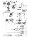
図1は、印刷工程の全体構成と本発明に係る印刷品質検査装置の一実施形態を示したブロック図である。この実施の形態に係る印刷品質検査装置は、ハードウェア領域に画像入力部3、画像処理部5、基準画像記憶部7、検査画像記憶部9、差分画像作成部11、マスク画像記憶部13、マスク処理部15および品質評価部17を備え、ソフトウェア領域にマスク画像作成部19および結果表示部21を備えている。
上記画像入力部3は、カメラやスキャナ等の画像入力手段で構成され、また、上記結果表示部21は、CRTやTFT液晶表示器等によって検査結果を表示する。
Hereinafter, embodiments of the present invention will be described with reference to the drawings.
FIG. 1 is a block diagram showing an overall configuration of a printing process and an embodiment of a print quality inspection apparatus according to the present invention. The print quality inspection apparatus according to this embodiment includes an
The
まず、印刷工程について説明する。デザイン部門31においては、顧客の要求に従い、画像作成ソフトを使用して印刷画像DTP(Desk Top Publish)を作成し、製版部門にこの印刷画像DTPの階調デジタルデータを転送する。製版展開部門33では、上記階調デジタルデータをRIP(Raster Image Processor)を用いて網点デジタルデータに変換し、該網点デジタルデータを基に製版装置35にて印刷版が作成される。
原画作成部37では、デザイン工程において作成された印刷画像を変換処理して、印刷作業工程で使用されるPPF(Print Production Format)の原画像を作成する。この原画作成部37によって作成された原画像のデータは、印刷用デジタルデータとして印刷機統括パソコン39を介して輪転・枚葉印刷機等の印刷機41に送られ、インキ供給量調整などに使用される。一方、上記原画像のデータ(印刷用デジタルデータ)は、上記マスク画像作成部13にも与えられる。
なお、上記原画像のPPFデータは、版画像のデータと比較して解像度が低く(版画像の解像度が2500dpi(dot/inches)程度であるのに対して、原画像のそれは通常0.5dpi程度である)、また網点デジタルデータではなく、階調デジタルデータである。
First, the printing process will be described. The design department 31 creates a print image DTP (Desk Top Publish) using image creation software in accordance with a customer's request, and transfers the gradation digital data of the print image DTP to the plate making department. In the plate making
The original
The PPF data of the original image has a lower resolution than the plate image data (the resolution of the plate image is about 2500 dpi (dot / inches), whereas that of the original image is usually about 0.5 dpi. It is not halftone digital data but gradation digital data.
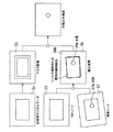
図2は、上記印刷品質検査装置を用いて実行される印刷品質検査手順の一例を示している。この手順においては、上流に位置された上記原画作成部37から上記原画像についてのデジタルデータを上記マスク画像作成部19に取り込む処理が実行され(ステップ100)、これにより、このマスク画像作成部19において後述のマスク画像(閾値画像)を生成する処理が実行される(ステップ101)。図3には、上記印刷用デジタルデータに対応する原画像51の例と、この印刷用デジタルデータに基づいて作成される上記マスク画像53の例が示されている。
FIG. 2 shows an example of a print quality inspection procedure executed using the print quality inspection apparatus. In this procedure, a process of taking digital data for the original image from the original
ところで、印刷機41は、前記網点デジタルデータに基づいて作成された印刷版を用いてテスト印刷を開始し、印刷物に上記原画像が適正に再現されるまでこのテスト印刷を継続する。もちろん、このテスト印刷中には、オペレータによって色調整等の調整操作が印刷機41に施される。
オペレータは、適正に刷り上った印刷物を基準とすべき印刷物(以下、OKシートと称する)として指定する。このOKシートは、前記画像入力部3に設けられたカメラやスキャナ等の画像入力手段によって撮影される(ステップ102)。そして、画像入力部3によって撮影されたOKシートの画像は、基準画像として前記画像処理部5を介して基準画像記憶部7に読み込まれる(ステップ103)。図3には、画像入力部3で撮影された基準画像55が例示されている。
Incidentally, the
The operator designates a printed matter that has been properly printed as a printed matter to be used as a reference (hereinafter referred to as an OK sheet). This OK sheet is photographed by image input means such as a camera or a scanner provided in the image input unit 3 (step 102). The image of the OK sheet taken by the
その後、印刷機は本刷りを開始する。この本刷り中においては、例えば、印刷版へのごみの付着等によって印刷物の品質が低下する虞がある。そこで、本刷りされた検査対象の印刷物(以下、検査シートという)が画像入力部3で撮影される(ステップ104)。この画像入力部3で撮影された画像は、検査画像として画像処理部5を介して検査画像記憶部9に読み込まれる(ステップ105)。
図3には、画像入力部3で撮影された検査画像57が示されている。この検査画像57中には、欠陥画像57aが含まれている。
Thereafter, the printing press starts full printing. During this final printing, for example, there is a possibility that the quality of the printed matter is deteriorated due to adhesion of dust to the printing plate. Therefore, the printed material to be inspected (hereinafter referred to as inspection sheet) is photographed by the image input unit 3 (step 104). The image photographed by the
FIG. 3 shows an
差分画像作成部11は、記憶部7および9から上記基準画像55および検査画像57を取り込んで、この基準画像55の各画素と検査画像57の対応する各画素の輝度差に基づく差分画像59を作成する(ステップ106)。
The difference image creation unit 11 takes in the
検査シートの画像を画像入力部3によって撮影する場合において、この検査シートがOKシートと同一の姿勢で配置されていれば、差分画像59において上記欠陥画像57aに基づく欠陥画像59aのみが表れることになる。
しかし、検査シートが傾斜して配置された場合には、図3に示すように、傾いた検査画像57が得られるので、基準画像55の縁部と検査画像77の縁部との位置ずれに起因した画像59bが差分画像59中に現れる。
When an image of the inspection sheet is taken by the
However, when the inspection sheet is arranged at an inclination, an
検査シートの検査は、差分画像59中における欠陥画像59aの有無を検査することを意味するので、上記画像59bを欠陥画像として抽出しないようにする必要がある。
前記マスク画像53は、上記画像59bを欠陥画像として抽出しないで、欠陥画像59aのみを抽出するために用いるものである。以下、このマスク画像53について詳細に説明する。
The inspection of the inspection sheet means that the presence or absence of the defect image 59a in the
The
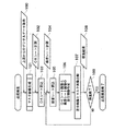
図4(a)は、前記印刷用デジタルデータに対応した互いに等しい2つの原画像51A,51Bを重ね合わした状態を示している。これらの原画像51A,51B上に例えば図示のような12の画素を設定した場合、原画像51A,51Bが正確に重なっている状態では、上記12の画素における原画像51Aの輝度と原画像51Bの輝度が等しいので、それらの輝度の差はゼロになる。
FIG. 4A shows a state in which two identical
しかし、原画像51Bが図4(b)のように傾斜している場合には、上記のように差分値がゼロにならない。なぜなら、例えば、画素bにおいては、原画像51Aの輝度値が100であるのに対し、原画像51Bの輝度値は100と20が混在して100よりも低くなるからである。
この場合、画素bにおける原画像51A,51Bの輝度差の大きさ(輝度差分値)に対する閾値を80(100−20)もしくはそれ以上に設定して、この閾値よりも小さい輝度差分値をマスクするようにすれば、この差分値をゼロとみなすことができる。
However, when the
In this case, the threshold for the magnitude of the luminance difference (luminance difference value) between the
一方、図4(b)において、画素aにおける原画像51A,51Bの輝度値は共に100であるので、この画素aでの輝度差分値はゼロになる。したがって、画素aの差分値に対する閾値はゼロで良いことになる。
On the other hand, in FIG. 4B, since the luminance values of the
前記マスク画像53は、図4(a)に示す各画素における原画像51A,51Bの輝度差分値の閾値を設定するものである。このマスク画像53は、原画像51Bが図4(c)に示す逆方向に傾斜することをも考慮に入れた場合、上記各画素について図4(d)のように作成される。すなわち、周辺の画素と輝度値の差が大きい画素では閾値が大きく、周辺の画素と輝度値の差が小さい画素では閾値が小さく設定される。
The
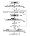
図5は、マスク画像作成部11で実行されるマスク画像53の作成手順を示している。この手順では、まず、回転角θを規定するパラメータ(θmin,θmax,N)が入力される(ステップ200)。なお、θmin,θmaxは想定される検査画像27の回転角の上限と下限を、また、Nは回転角範囲θmin〜θmaxの変化ステップ数を示している。
FIG. 5 shows a creation procedure of the
次に、回転角θの番号nを0に初期化した後、回転角θをθ=θmin+{n(θmax−θmin)N}として設定し(ステップ201,202)、この回転角θだけ回転した図4(b)に示すような画像を作成する(ステップ203)。そして、図4(a)に例示した各画素において、無回転画像51Aと回転画像51Bの輝度差分を算出する(ステップ204)。
Next, after the number n of the rotation angle θ is initialized to 0, the rotation angle θ is set as θ = θ min + {n (θ max −θ min ) N} (
次に、nの値が1だけ増加されたあと、nがNよりも小さいか否かが判断される(ステップ205,206)。そして、その判断結果がyesの場合には手順がステップ203に戻され、noの場合には、各画素に於いて最大となった輝度差分値をマスク画像の各画素における輝度値(閾値)とする(ステップ207)。
上記のようにして作成されるマスク画像53は、スク画像記憶部13に記憶される。
Next, after the value of n is increased by 1, it is determined whether or not n is smaller than N (
The
ところで、上記マスク画像53は、上記無回転画像51Aと回転画像51Bとして基準画像55を用いても作成することができる。しかし、このように基準画像55に基づいてマスク画像53を作成しよとすると、この基準画像55を得た後、このマスク画像53を作成する時間が経過した時点で本刷りが開始されることになるので、印刷作業の効率が著しく阻害されることになる。
By the way, the
そこで、この実施の形態では、前記印刷用デジタルデータに対応する原画像の各画素の輝度が上記基準画像の輝度とほぼ一致していることに着目して、前記したように、印刷用デジタルデータを用いてマスク画像53を作成している。
このように、印刷用デジタルデータに基づいてマスク画像53を作成する手法を採用すれば、基準画像55の取得時点以前に、つまり、前記テスト刷りの終了時点以前にマスク画像53の作成を終了することが可能になるので、テスト刷りの終了後、直ちに本刷り移行することができ、この結果、印刷作業の効率が向上する。
Therefore, in this embodiment, paying attention to the fact that the luminance of each pixel of the original image corresponding to the printing digital data substantially matches the luminance of the reference image, as described above, the printing digital data Is used to create a
As described above, if the method of creating the
再び、図2の品質検査手順を参照する。図2のステップ107においては、前記マスク処理部15によって図3に示す差分画像59とマスク画像53とが比較される。
上記印刷用デジタルデータに基づいて作成されたマスク画像53では、上記差分画像59中の画像59bを含む周辺画素領域をマスクし得るように、この周辺画素領域に対応する領域53a(四角状の枠で示す)に画像59bの輝度値よりも高い輝度閾値が設定され、また、上記画素領域53aを除く画素領域に欠陥画像59aの抽出が可能な低輝度閾値が設定されている。
Again, reference is made to the quality inspection procedure of FIG. In
In the
マスク処理部15は、個々の画素において、差分画像59の輝度値とマスク画像の輝度値(閾値)とを比較して、マスク画像の輝度値より大きい輝度値を有する差分画像を欠陥画像59aとして検出し、この欠陥画像59aとその位置のデータとを検査結果として前記品質評価部17に出力する(ステップ108)。
上記のような品質検査は、本刷りされた全ての印刷物あるいは一部の印刷物に対して実行され、それらの印刷物の検査の終了がステップ109において判断された時点で検査作業が終了する。
For each pixel, the mask processing unit 15 compares the luminance value of the
The quality inspection as described above is performed on all printed materials or a part of the printed materials, and the inspection operation is completed when it is determined in
上述したように、この実施の形態においては、印刷用デジタルデータに基づいてマスク画像53を作成するので、基準画像55の取得を待つことなくマスク画像53の作成に着手することができる。したがって、前記テスト刷りの終了前にマスク画像53を用いた品質検査の体制を整えて、テスト刷りの後に直ちに本刷りに移行することが可能になる。また、マスク画像53の作成に十分な時間を確保することができるので、新たに高価な専用処理装置を装備することなく、一般的なパーソナルコンピュータ等でマスク画像53を作成することが可能になる。
As described above, in this embodiment, since the
1 品質検査装置
3 画像入力部
5 画像処理部
7 基準画像記憶部
9 検査画像記憶部
11 差分画像作成部
13 マスク画像記憶部
15 マスク処理部
17 品質評価部
51 原画像
53 マスク画像
55 基準画像
57 検査画像
59 差分画像
DESCRIPTION OF
Claims (4)
前記印刷用デジタルデータに基づいて印刷された基準となる印刷物を画像入力手段で撮影して基準画像を得るステップと、
前記印刷用デジタルデータに基づいて印刷された検査すべき印刷物を画像入力手段で撮影して検査画像を得るステップと、
前記基準画像と検査画像の各画素の輝度の差を示す差分画像を作成するステップと、
前記差分画像の各画素の輝度に対する閾値を示すマスク画像を前記印刷用デジタルデータに基づいて作成するステップと、
前記差分画像とマスク画像とを比較して、欠陥画像とその位置を抽出するステップと、
を含むことを特徴とする印刷品質の検査方法。 A method for inspecting the print quality of a printed material printed based on digital data for printing,
Taking a reference printed matter printed based on the digital data for printing with an image input means to obtain a reference image; and
Photographing a printed matter to be inspected based on the digital data for printing with an image input means to obtain an inspection image;
Creating a difference image indicating a difference in luminance of each pixel of the reference image and the inspection image;
Creating a mask image indicating a threshold for the luminance of each pixel of the difference image based on the digital data for printing;
Comparing the difference image and the mask image to extract a defect image and its position;
A method for inspecting print quality, comprising:
前記印刷用デジタルデータに対応する2つの原画像を作成するステップと、
前記2つの原画像の一方を他方に対して所定角度間隔で繰返し回転させるス
テップと、
前記所定角度間隔の回転が実行される度に、前記一方の原画像と他方の原画
像の各画素についての輝度の差分値を算出するステップと、
前記各画素において最大となった輝度差分値を前記マスク画像の各画素における閾値として設定するステップと、
を含むことを特徴とする請求項1に記載の印刷品質の検査方法。 The step of creating the mask image based on the printing digital data includes:
Creating two original images corresponding to the digital data for printing;
Repeatedly rotating one of the two original images at a predetermined angular interval with respect to the other;
Calculating a luminance difference value for each pixel of the one original image and the other original image each time rotation of the predetermined angular interval is performed;
Setting a luminance difference value that is maximized in each pixel as a threshold value in each pixel of the mask image;
The print quality inspection method according to claim 1, further comprising:
前記印刷用デジタルデータに基づいて印刷された基準となる印刷物を撮影して基準画像を得る画像入力手段と、
前記印刷用デジタルデータに基づいて印刷された検査すべき印刷物を撮影して検査画像を得る画像入力手段と、
前記基準画像と検査画像の各画素の輝度の差を示す差分画像を作成する差分画像作成手段と、
前記差分画像の各画素の輝度に対する閾値を示すマスク画像を前記印刷用デジタルデータに基づいて作成するマスク画像作成手段と、
前記差分画像とマスク画像とを比較して、欠陥画像とその位置を抽出する欠陥画像抽出手段と、
を備えることを特徴とする印刷品質の検査装置。 An apparatus for inspecting the print quality of printed matter printed based on digital data for printing,
Image input means for obtaining a reference image by photographing a printed matter as a reference printed based on the digital data for printing;
Image input means for obtaining an inspection image by photographing a printed matter to be inspected printed based on the digital data for printing;
A difference image creating means for creating a difference image indicating a difference in luminance of each pixel of the reference image and the inspection image;
A mask image creating means for creating a mask image indicating a threshold for the luminance of each pixel of the difference image based on the digital data for printing;
A defect image extracting means for comparing the difference image with the mask image and extracting a defect image and its position;
An inspection apparatus for print quality, comprising:
像を作成する処理と、前記2つの原画像の一方を他方に対して所定角度間隔で繰返し回転させる処理と、前記所定角度間隔の回転が実行される度に、前記一方の原画像と他方の原画像の各画素についての輝度の差分値を算出する処理と、前記各画素において最大となった輝度差分値を前記マスク画像の各画素における閾値として設定する処理と、を実行する手段を備えることを特徴とする請求項3に記載の印刷品質の検査装置。 The mask image creating means includes a process of creating two original images corresponding to the printing digital data, a process of repeatedly rotating one of the two original images at a predetermined angle interval with respect to the other, and the predetermined angle Each time the rotation of the interval is executed, a process for calculating a difference value of luminance for each pixel of the one original image and the other original image, and a luminance difference value that is maximized in each pixel is set to the mask image. The print quality inspection apparatus according to claim 3, further comprising: a unit configured to execute processing for setting a threshold value for each of the pixels.
Priority Applications (1)
| Application Number | Priority Date | Filing Date | Title |
|---|---|---|---|
| JP2004119061A JP2005297438A (en) | 2004-04-14 | 2004-04-14 | Method and equipment for inspecting print quality |
Applications Claiming Priority (1)
| Application Number | Priority Date | Filing Date | Title |
|---|---|---|---|
| JP2004119061A JP2005297438A (en) | 2004-04-14 | 2004-04-14 | Method and equipment for inspecting print quality |
Publications (1)
| Publication Number | Publication Date |
|---|---|
| JP2005297438A true JP2005297438A (en) | 2005-10-27 |
Family
ID=35329565
Family Applications (1)
| Application Number | Title | Priority Date | Filing Date |
|---|---|---|---|
| JP2004119061A Withdrawn JP2005297438A (en) | 2004-04-14 | 2004-04-14 | Method and equipment for inspecting print quality |
Country Status (1)
| Country | Link |
|---|---|
| JP (1) | JP2005297438A (en) |
Cited By (1)
| Publication number | Priority date | Publication date | Assignee | Title |
|---|---|---|---|---|
| CN114820553A (en) * | 2015-09-23 | 2022-07-29 | 英特美克技术公司 | Evaluating images |
-
2004
- 2004-04-14 JP JP2004119061A patent/JP2005297438A/en not_active Withdrawn
Cited By (1)
| Publication number | Priority date | Publication date | Assignee | Title |
|---|---|---|---|---|
| CN114820553A (en) * | 2015-09-23 | 2022-07-29 | 英特美克技术公司 | Evaluating images |
Similar Documents
| Publication | Publication Date | Title |
|---|---|---|
| JP4055385B2 (en) | Image inspection device | |
| US7440123B2 (en) | Adaptive printing | |
| JP2014117875A (en) | Image formation apparatus, inspection device, image formation apparatus control method, inspection device control method, and program | |
| JP6180674B1 (en) | Image inspection method with multiple cameras | |
| JP2005205693A (en) | Inspection device, inspection program, inspection method, controller, control program and control method | |
| JP7608757B2 (en) | Printing inspection device and printing inspection program | |
| JP3242008B2 (en) | Image inspection method and image inspection apparatus in plate making process | |
| JP2007226616A (en) | Printed matter inspection apparatus, printed matter inspection method, printing apparatus, printing method, program, recording medium | |
| JP2005316550A (en) | Image processor, image reader, image inspection device and program | |
| JP3204876B2 (en) | Print inspection equipment | |
| JP2005297438A (en) | Method and equipment for inspecting print quality | |
| JP5710101B2 (en) | Printed matter inspection apparatus and printed matter inspection method | |
| JP4779445B2 (en) | Editing device, editing program and editing system | |
| JP2023110836A5 (en) | ||
| CN117745629A (en) | Image processing apparatus, storage medium, and image processing method | |
| JP2004098489A (en) | Image output apparatus | |
| JP2008014703A (en) | Image flaw inspection system, image flaw inspection method and program | |
| JP2004094438A (en) | Image inspecting device and program | |
| JPH09133514A (en) | Image measuring device | |
| JP2005196659A (en) | Program, recording medium and apparatus for processing image | |
| JP3317403B2 (en) | Image data inspection method, plate inspection method, computer readable recording medium recording image data inspection program, and computer readable recording medium recording plate inspection program | |
| JP2008049520A (en) | Printed matter inspection apparatus and printed matter inspection method | |
| JP2005119261A5 (en) | ||
| JP2002174600A (en) | Apparatus for detecting surface flaw of steel sheet, detection method, and storage medium | |
| JPH08323964A (en) | Position sensing device for register mark |
Legal Events
| Date | Code | Title | Description |
|---|---|---|---|
| A300 | Withdrawal of application because of no request for examination |
Free format text: JAPANESE INTERMEDIATE CODE: A300 Effective date: 20070703 |