JP2005297313A - Image forming apparatus - Google Patents
Image forming apparatus Download PDFInfo
- Publication number
- JP2005297313A JP2005297313A JP2004115375A JP2004115375A JP2005297313A JP 2005297313 A JP2005297313 A JP 2005297313A JP 2004115375 A JP2004115375 A JP 2004115375A JP 2004115375 A JP2004115375 A JP 2004115375A JP 2005297313 A JP2005297313 A JP 2005297313A
- Authority
- JP
- Japan
- Prior art keywords
- job
- tray
- output
- unit
- order
- Prior art date
- Legal status (The legal status is an assumption and is not a legal conclusion. Google has not performed a legal analysis and makes no representation as to the accuracy of the status listed.)
- Pending
Links
- 230000008707 rearrangement Effects 0.000 claims abstract description 174
- 238000001514 detection method Methods 0.000 claims description 29
- 238000012545 processing Methods 0.000 description 31
- 238000012805 post-processing Methods 0.000 description 22
- 238000010586 diagram Methods 0.000 description 17
- 230000002093 peripheral effect Effects 0.000 description 17
- 238000005259 measurement Methods 0.000 description 15
- 239000011521 glass Substances 0.000 description 8
- 238000000034 method Methods 0.000 description 7
- 230000008569 process Effects 0.000 description 7
- 230000032258 transport Effects 0.000 description 7
- 238000003825 pressing Methods 0.000 description 5
- 230000006870 function Effects 0.000 description 4
- 230000015572 biosynthetic process Effects 0.000 description 3
- 210000000078 claw Anatomy 0.000 description 2
- 238000004140 cleaning Methods 0.000 description 2
- 238000007599 discharging Methods 0.000 description 2
- 230000010365 information processing Effects 0.000 description 2
- 238000005192 partition Methods 0.000 description 2
- 230000004044 response Effects 0.000 description 2
- 230000005540 biological transmission Effects 0.000 description 1
- 238000006243 chemical reaction Methods 0.000 description 1
- 239000002131 composite material Substances 0.000 description 1
- 230000003028 elevating effect Effects 0.000 description 1
- 239000004973 liquid crystal related substance Substances 0.000 description 1
- 230000009467 reduction Effects 0.000 description 1
- 230000001105 regulatory effect Effects 0.000 description 1
- 238000011144 upstream manufacturing Methods 0.000 description 1
Images


Landscapes
- Facsimiles In General (AREA)
- Accessory Devices And Overall Control Thereof (AREA)
- Record Information Processing For Printing (AREA)
- Control Or Security For Electrophotography (AREA)
Abstract
Description
本発明は、複写機や複合機等の画像形成装置に関し、特に、各印刷ジョブに応じて複数種類のトレイを用紙排出口に対して移動させることが可能な画像形成装置に関する。 The present invention relates to an image forming apparatus such as a copying machine or a multifunction peripheral, and more particularly to an image forming apparatus capable of moving a plurality of types of trays with respect to a sheet discharge port in accordance with each print job.
従来、複写機や複合機等の画像形成装置において、用紙排出口に対して昇降移動可能な複数のトレイを備え、各ユーザからのジョブの出力先としてのトレイが選択され、当該選択されたトレイに用紙を出力(排出)させることが可能に構成されたものがある。 2. Description of the Related Art Conventionally, an image forming apparatus such as a copying machine or a multi-function peripheral has a plurality of trays that can be moved up and down with respect to a sheet discharge port, and a tray as a job output destination from each user is selected. Is configured to output (discharge) paper.
具体的には、1つの用紙排出口に対して、メイントレイ(下部シート積載部)及び複数の区分トレイから構成される多段トレイ(上部シート積載部)からなる各トレイをそれぞれ昇降移動させることが可能に構成されており、メイントレイが、例えばコピー時における用紙排出用の大容量トレイとして使用され(コピー時には、メイントレイは、用紙排出口に対向する位置に配置されており、多段トレイはメイントレイの上方位置に配置されている)、一方、多段トレイを構成する区分トレイが、例えば、装置本体とLAN等によって接続された各ユーザの情報処理装置、例えばPC(パーソナルコンピュータ)毎に割り当てられたトレイ、すなわち、各ユーザのジョブの出力に対応するトレイとして使用される画像形成装置がある(例えば、特許文献1参照)。
ところで、複数のユーザ(PC)からのジョブの出力が行われる場合、各ジョブに対して割り当てられているトレイへの出力が、当該ジョブが装置に受け付けられた順番(受付順)で行われるため(出力される順番が受付順に固定されているため)、トレイの昇降移動もこの順番で行われ、場合によっては、上方のトレイ及び下方のトレイへの昇降移動が交互に繰り返されながらジョブの出力が行われてしまう。例えば或るユーザが複数のジョブを出力する際、このジョブ間に他のユーザのジョブが混在している場合には、この他のユーザの出力用のトレイが、或るユーザ用のトレイから遠く離れた位置のトレイであったとしてもそのトレイが用紙排出口の位置にくるまで昇降移動が行われてしまう。このように、ジョブを急ぎ出力したい場合であっても受付順に従ってトレイが昇降移動されてしまうため、トレイの昇降移動に長い時間がかかるなどしてしまい、各ジョブに対する出力が効率良く行えないといった問題があった。 When jobs are output from a plurality of users (PCs), output to the tray assigned to each job is performed in the order in which the jobs are received by the apparatus (reception order). (Because the output order is fixed in the order of acceptance), the trays are also moved up and down in this order. In some cases, the output of the job is repeated while the up and down movements to the upper tray and the lower tray are repeated alternately. Will be done. For example, when a certain user outputs a plurality of jobs, and another user's job is mixed between the jobs, the output tray of the other user is far from the tray for the certain user. Even if the tray is at a distant position, the tray is moved up and down until the tray comes to the position of the paper discharge port. In this way, even if it is desired to output a job in a hurry, the tray is moved up and down in accordance with the order of acceptance, so it takes a long time to move the tray up and down, and output for each job cannot be performed efficiently. There was a problem.
本発明は上記問題に鑑みてなされたもので、ジョブの出力が受付順に固定されることなく、すなわち、ジョブの受付順に従ってトレイが移動され、場合によっては不必要な移動(昇降移動)が繰り返されてしまうといったことなく、各ユーザのジョブの出力を効率良く行うことができる画像形成装置を提供することを目的とする。 The present invention has been made in view of the above problems, and the output of jobs is not fixed in the order of acceptance, that is, the tray is moved according to the order of acceptance of jobs, and in some cases, unnecessary movement (up and down movement) is repeated. It is an object of the present invention to provide an image forming apparatus that can efficiently output a job of each user without being lost.
本発明に係る画像形成装置は、用紙が排出される複数のトレイを備え、当該各トレイを各ユーザのジョブに対応させて用紙排出口に対して選択的に対向させることが可能に構成された画像形成装置であって、前記ジョブを受け付ける受付手段と、所定時間の計測を行うとともに、所定時間内において前記受付手段によって受け付けられた時間受付ジョブ及び当該時間受付ジョブの受付順を識別する識別手段と、時間受付ジョブの出力順の並べ替えを行うための所定の条件を示す並替情報を設定する設定手段と、前記設定手段によって設定された並替情報と、前記識別手段によって識別された受付順の情報とに基づいて、時間受付ジョブの出力順の並べ替えを行う並替手段とを備えることを特徴とする。 The image forming apparatus according to the present invention includes a plurality of trays from which paper is discharged, and each tray can be selectively opposed to a paper discharge port in correspondence with each user's job. An image forming apparatus for receiving the job and an identification unit for measuring a predetermined time and identifying a time receiving job received by the receiving unit within a predetermined time and a receiving order of the time receiving job Setting means for setting rearrangement information indicating a predetermined condition for rearranging the output order of the time reception job, the rearrangement information set by the setting means, and the reception identified by the identification means Reordering means for reordering the output order of the time receiving jobs based on the order information.
上記構成によれば、各ユーザからのジョブが受付手段によって受け付けられ、所定時間の計測が行われるとともに、この所定時間内において受付手段により受け付けられた時間受付ジョブ及び当該時間受付ジョブの受付順が識別手段によって識別される。そして、設定手段によって時間受付ジョブの出力順の並べ替えを行うための所定の条件を示す並替情報が設定され、この設定手段によって設定された並替情報と、識別手段によって識別された受付順の情報とに基づいて、時間受付ジョブの出力順の並べ替えが並替手段によって行われる。 According to the above configuration, a job from each user is received by the receiving unit, measurement of a predetermined time is performed, and the time receiving job received by the receiving unit within the predetermined time and the receiving order of the time receiving job are It is identified by the identification means. Then, rearrangement information indicating a predetermined condition for rearranging the output order of the time reception job is set by the setting unit, the rearrangement information set by the setting unit, and the reception order identified by the identification unit Based on the above information, the output order of the time reception job is rearranged by the rearranging means.
また、前記識別手段によって識別された時間受付ジョブにおける同じユーザのジョブを判別するジョブ判別手段をさらに備え、前記設定手段は、ジョブ判別手段によって判別された同じユーザのジョブを続けて出力させるべく時間受付ジョブの並べ替えを行う同ユーザ並替情報を設定し、前記並替手段は、前記設定手段によって設定された同ユーザ並替情報と、前記受付順の情報とに基づいて、時間受付ジョブの出力順の並べ替えを行うことが好ましい。 Further, the apparatus further comprises job discrimination means for discriminating a job of the same user in the time reception job identified by the discrimination means, and the setting means is configured to output the job of the same user discriminated by the job discrimination means for a time to be continuously output. The same user rearrangement information for rearranging the reception jobs is set, and the rearrangement unit determines the time reception job based on the same user rearrangement information set by the setting unit and the information on the reception order. It is preferable to rearrange the output order.
これによれば、識別手段により識別された時間受付ジョブにおける同じユーザのジョブがジョブ判別手段によって判別され、当該ジョブ判別手段により判別された同じユーザのジョブを続けて出力させるべく時間受付ジョブの並べ替えを行う同ユーザ並替情報が設定手段によって設定される。そして、設定手段により設定された同ユーザ並替情報と、受付手段による時間受付ジョブの受付順の情報とに基づいて、当該時間受付ジョブの出力順の並べ替えが並替手段によって行われる。 According to this, the job of the same user in the time reception job identified by the identification unit is determined by the job determination unit, and the time reception job is arranged in order to continuously output the job of the same user determined by the job determination unit. The same user rearrangement information to be replaced is set by the setting means. Then, based on the same user rearrangement information set by the setting means and information on the order of reception of time reception jobs by the reception means, the output means rearranges the output order of the time reception jobs.
また、用紙排出口にいずれのトレイが対向しているかを検出するトレイ検出手段と、前記トレイ検出手段による検出情報に基づいて、用紙排出口に近い位置にあるトレイを判別するトレイ判別手段とをさらに備え、前記設定手段は、トレイ判別手段によって判別された近い位置のトレイに出力させるべく時間受付ジョブの並べ替えを行うトレイ並替情報をさらに設定し、前記並替手段は、前記設定手段によって設定された前記同ユーザ並替情報及びトレイ並替情報と、前記受付順の情報とに基づいて、時間受付ジョブの出力順の並べ替えを行うことが好ましい。 A tray detection unit that detects which tray is opposed to the paper discharge port; and a tray determination unit that determines a tray near the paper discharge port based on information detected by the tray detection unit. The setting means further sets tray rearrangement information for rearranging time reception jobs to be output to a tray at a close position determined by the tray determination means. It is preferable to rearrange the output order of the time reception jobs based on the set user rearrangement information and tray rearrangement information and the reception order information.
これによれば、トレイ検出手段によって用紙排出口にいずれのトレイが対向しているかが検出され、このトレイ検出手段による検出情報に基づいて、用紙排出口に近い位置にあるトレイがトレイ判別手段によって判別される。また、設定手段によって、トレイ判別手段によって判別された近い位置のトレイに出力させるべく時間受付ジョブの並べ替えを行うトレイ並替情報がさらに設定され、設定手段により設定された同ユーザ並替情報及びトレイ並替情報と、受付手段による時間受付ジョブの受付順の情報とに基づいて、当該時間受付ジョブの出力順の並べ替えが並替手段によって行われる。 According to this, the tray detection unit detects which tray is opposed to the paper discharge port, and based on the detection information by the tray detection unit, the tray near the paper discharge port is detected by the tray determination unit. Determined. Further, the setting means further sets tray reordering information for reordering the time reception jobs to be output to the near-positioned tray determined by the tray determining means, and the same user reordering information set by the setting means and Based on the tray rearrangement information and the information on the order of reception of the time reception job by the reception unit, the rearrangement unit performs the rearrangement of the output order of the time reception job.
また、前記識別手段によって識別された時間受付ジョブにおける出力用紙枚数を判別する枚数判別手段をさらに備え、前記設定手段は、枚数判別手段によって判別された出力用紙枚数に基づいて時間受付ジョブの並べ替えを行う枚数並替情報を設定し、前記並替手段は、前記設定手段によって設定された枚数並替情報と、前記受付順の情報とに基づいて、時間受付ジョブの出力順の並べ替えを行うことが好ましい。 In addition, a sheet number discriminating unit that discriminates the number of output sheets in the time receiving job identified by the identifying unit is further provided, and the setting unit rearranges the time receiving jobs based on the number of output sheets discriminated by the number discriminating unit. The rearrangement unit rearranges the output order of the time reception job based on the number rearrangement information set by the setting unit and the reception order information. It is preferable.
これによれば、識別手段により識別された時間受付ジョブにおける出力用紙枚数が枚数判別手段によって判別され、枚数判別手段により判別された出力用紙枚数に基づいて時間受付ジョブの並べ替えを行う枚数並替情報が設定手段によって設定され、設定手段により設定された枚数並替情報と、受付手段による時間受付ジョブの受付順の情報とに基づいて、当該時間受付ジョブの出力順の並べ替えが並替手段によって行われる。 According to this, the number of output sheets in the time reception job identified by the identification unit is determined by the number determination unit, and the number of output sheets is rearranged based on the number of output sheets determined by the number determination unit. The information is set by the setting means, and based on the number rearrangement information set by the setting means and the information on the reception order of the time reception jobs by the reception means, the rearrangement of the output order of the time reception jobs is performed by the rearrangement means. Is done by.
また、前記設定手段は、出力用紙枚数の少ない時間受付ジョブから出力させるべく時間受付ジョブの並べ替えを行う枚数並替情報を設定することが好ましい。これによれば、設定手段によって、出力用紙枚数の少ない時間受付ジョブから出力させるべく時間受付ジョブの並べ替えを行う枚数並替情報が設定される。 Further, it is preferable that the setting unit sets sheet number rearrangement information for rearranging time reception jobs so as to be output from a time reception job with a small number of output sheets. According to this, the sheet number rearrangement information for rearranging the time reception job to be output from the time reception job with a small number of output sheets is set by the setting means.
また、前記設定手段は、固定された所定の出力順に出力させるべく時間受付ジョブの並べ替えを行う固定並替情報を設定し、前記並替手段は、前記設定手段によって設定された固定並替情報と、前記受付順の情報とに基づいて、時間受付ジョブの出力順の並べ替えを行うことが好ましい。 The setting means sets fixed reordering information for reordering time reception jobs to be output in a fixed predetermined output order, and the reordering means sets the fixed reordering information set by the setting means. It is preferable to rearrange the output order of time reception jobs based on the reception order information.
これによれば、固定された所定の出力順に出力させるべく時間受付ジョブの並べ替えを行う固定並替情報が設定手段によって設定され、設定手段により設定された固定並替情報と、受付手段による時間受付ジョブの受付順の情報とに基づいて、当該時間受付ジョブの出力順の並べ替えが並替手段によって行われる。 According to this, fixed rearrangement information for rearranging time reception jobs to be output in a fixed predetermined output order is set by the setting unit, the fixed rearrangement information set by the setting unit, and the time by the reception unit Based on the reception order information of the reception job, the rearrangement unit rearranges the output order of the time reception job.
また、前記設定手段は、各トレイのうちの一のトレイに対して、遠い位置のトレイから順に出力させるべく時間受付ジョブの並べ替えを行う固定並替情報を設定することが好ましい。これによれば、設定手段によって、各トレイのうちの一のトレイに対して、遠い位置のトレイから順に出力させるべく時間受付ジョブの並べ替えを行う固定並替情報が設定される。 Further, it is preferable that the setting unit sets fixed rearrangement information for rearranging time reception jobs so that one tray among the trays is sequentially output from a tray at a far position. According to this, the fixed reordering information for reordering the time reception jobs is set by the setting means so that one of the trays is sequentially output from the distant tray.
請求項1記載の発明によれば、所定時間内に受付手段により受け付けられた時間受付ジョブと、当該時間受付ジョブの受付順とが識別手段によって識別され、設定手段により設定された並替情報と、識別手段により識別された時間受付ジョブの受付順の情報とに基づいて、並替手段によって時間受付ジョブの出力順の並べ替えが行われるため、ジョブの出力が受付順に固定されることなく、すなわち、ジョブの受付順に従ってトレイが移動されてしまい、場合によっては不必要な昇降移動が繰り返されてしまう、といったことなく、各ユーザのジョブの出力を効率良く行うことができる。 According to the first aspect of the present invention, the time reception job received by the reception unit within a predetermined time and the reception order of the time reception job are identified by the identification unit, and the reordering information set by the setting unit Based on the information of the reception order of the time reception job identified by the identification unit, the rearrangement unit rearranges the output order of the time reception job, so that the job output is not fixed in the reception order, That is, it is possible to efficiently output the job of each user without the tray being moved in accordance with the job reception order and unnecessary up and down movement being repeated in some cases.
請求項2記載の発明によれば、時間受付ジョブにおける同じユーザのジョブがジョブ判別手段によって判別され、同ユーザ並替情報と、時間受付ジョブの受付順の情報とに基づいて、並替手段によって時間受付ジョブの出力順の並べ替えが行われるため、時間受付ジョブのうちの同じユーザのジョブを続けて(連続させて)出力されることが可能となり、トレイを昇降移動させる時間を短縮する(トレイの昇降移動(回数)を低減させる)ことができる。 According to the second aspect of the present invention, jobs of the same user in the time reception job are determined by the job determination unit, and based on the user rearrangement information and information on the order of reception of the time reception job, the rearrangement unit Since the output order of the time reception jobs is rearranged, jobs of the same user among the time reception jobs can be output continuously (continuously), and the time for moving the tray up and down can be reduced ( (Traft movement (number of times) of the tray can be reduced).
請求項3記載の発明によれば、トレイ検出手段による検出情報に基づいて用紙排出口に近い位置にあるトレイがトレイ判別手段によって判別され、同ユーザ並替情報及びトレイ並替情報と、時間受付ジョブの受付順の情報とに基づいて、並替手段によって時間受付ジョブの出力順の並べ替えが行われるため、同じユーザのジョブを続けて出力することができるとともに、用紙排出口により近い位置のトレイから順に出力(排出)させることができ、トレイを昇降移動させる時間をより短縮することができる。 According to the third aspect of the present invention, the tray discriminating unit discriminates the tray in the position close to the paper discharge port based on the detection information by the tray detecting unit, and the user rearrangement information and the tray rearrangement information are received. Based on the job reception order information, the rearrangement unit rearranges the output order of the time reception job, so that the same user's job can be output continuously and the position closer to the paper discharge port. Output (discharge) can be performed sequentially from the tray, and the time for moving the tray up and down can be further reduced.
請求項4記載の発明によれば、時間受付ジョブにおける出力用紙枚数が枚数判別手段によって判別され、枚数並替情報と、時間受付ジョブの受付順の情報とに基づいて、並替手段によって時間受付ジョブの出力順の並べ替えが行われるため、所定時間内に受け付けられたジョブの出力用紙枚数を考慮して出力させることが可能となり、すなわち、例えば少ない出力用紙枚数のジョブから順に出力させたり、あるいは多い出力用紙枚数のジョブから順に出力させたりすることが可能となり、ひいては各ユーザのジョブの出力を効率良く行うことができる。
According to the invention described in
請求項5記載の発明によれば、設定手段に出力用紙枚数の少ない時間受付ジョブから出力させるべく時間受付ジョブの並べ替えを行う枚数並替情報が設定されるため、出力用紙枚数の少ないジョブから順に出力させることができ、或るユーザによる出力用紙枚数が多いジョブの出力によって、少枚数のジョブを出力を行おうとしているユーザが長時間待たされるといったことをなくすことができ、ひいては各ユーザのジョブの出力を効率良く行うことができる。 According to the fifth aspect of the invention, since the sheet number rearrangement information for rearranging the time receiving job is set in the setting means so that the time receiving job is output from the time receiving job with the smaller number of output paper sheets, The output of a job with a large number of output sheets by a certain user can be prevented from waiting for a long time for a user who wants to output a small number of jobs. Job output can be performed efficiently.
請求項6記載の発明によれば、固定された所定の出力順に出力させるべく時間受付ジョブの並べ替えを行う固定並替情報が設定手段によって設定され、この固定並替情報と、時間受付ジョブの受付順の情報とに基づいて、並替手段によって時間受付ジョブの出力順の並べ替えが行われるため、同じユーザからのジョブであるか、あるいはジョブの枚数が何枚であるかなどといった判別動作(制御)を行う必要がなく、より簡易な構成で、或る固定された(予め設定された)出力順、例えば最上位置又は最下位置のトレイから順に隣のトレイに出力させていくといったことが可能となり、ひいては効率良いジョブの出力が可能となる。 According to the sixth aspect of the invention, the fixed rearrangement information for rearranging the time reception job to be output in the predetermined order of output is set by the setting means, and the fixed rearrangement information and the time reception job Based on the information of the order of acceptance, the order of output of time acceptance jobs is rearranged by the rearrangement means, so that it is a discriminating operation such as whether the jobs are from the same user or the number of jobs (Control) is not required, and output is performed in a fixed (preset) output order, for example, from the uppermost tray or the lowermost tray to the next tray in order, with a simpler configuration. As a result, efficient job output is possible.
請求項7記載の発明によれば、設定手段に各トレイのうちの一のトレイに対して遠い位置のトレイから順に出力させるべく時間受付ジョブの並べ替えを行う固定並替情報が設定されるため、各トレイのうちの一のトレイ、例えばデフォルトの出力先として設定されているメイントレイ(大容量トレイ)に対し、遠い位置のトレイに対応したジョブから順に出力させ、メイントレイに対してより近い位置のトレイにおいてジョブの出力を終了させることが可能となり、メイントレイを用紙排出口の位置(ホームポジション)まで戻すためのトレイの移動時間を短縮することができる。すなわち、ジョブ出力を行うべくトレイの昇降移動を行い、出力終了後にもさらにメイントレイをホームポジションに戻すべく、場合によっては長い距離を移動させるといったことが不要となる。 According to the seventh aspect of the present invention, the fixed reordering information for reordering the time reception jobs is set so that the setting means sequentially outputs from the tray far from the one of the trays. , One tray of each tray, for example, the main tray (large capacity tray) set as the default output destination is output in order starting from the job corresponding to the farther tray, and closer to the main tray The output of the job can be ended in the tray at the position, and the time for moving the tray for returning the main tray to the position of the paper discharge port (home position) can be shortened. In other words, it is not necessary to move the tray up and down to perform job output and to move the main tray over a long distance in some cases to return the main tray to the home position after completion of output.
以下、本発明に係る画像形成装置の一例としての複合機について図面を参照しながら説明する。なお、各図において同一の符号を付した構成は、同一の構成であることを示している。 Hereinafter, a multifunction peripheral as an example of an image forming apparatus according to the present invention will be described with reference to the drawings. In addition, the structure which attached | subjected the same code | symbol in each figure has shown that it is the same structure.
(第1実施形態)
図1は、本発明の複合機を用いたネットワークシステムの構成例である。図1に示すネットワークシステムは、複合機1、複数のPC2等の情報処理装置を備える。複合機1は、プリンタ機能、コピー機能、スキャナ機能等の複合機能を備えた画像形成装置であり、ネットワークの一例であるLAN(Local Area Network)3を介してPC2と通信可能に接続され、PC2と種々のデータ等の送受信が可能な状態に構成されている。また、複合機1は、PC2から送信された所定の画像データを受信し、この受信した画像データに対する画像を出力(プリント)することが可能な構成となっている。
(First embodiment)
FIG. 1 is a configuration example of a network system using a multifunction machine of the present invention. The network system shown in FIG. 1 includes an information processing apparatus such as a
図2は、本発明の第1の実施形態に係る画像形成装置の一例である複合機1の内部構成
を概略的に示す断面図である。複合機1は、画像形成部100を備えた本体部10、本体部10の上方に設置された原稿給送部200及び原稿読取部300、本体部10の下部に設置されたに給紙部400、本体部10の一側辺部に設置された後処理部500、本体部10のフロント部に設置された操作表示部600並びに検出部700を備える。
FIG. 2 is a cross-sectional view schematically showing an internal configuration of the
原稿読取部300は、原稿の読み取りを行って当該原稿に対応する画像データを生成するものである。原稿読取部300は、光学的に取得した原稿の画像から画像データを生成するCCD(Charge Coupled Device)センサ及び露光ランプ等を備えたスキャナ301などからなり、その上面に第1コンタクトガラス302及び第2コンタクトガラス303を備えている。原稿読取部300は、第1コンタクトガラス302上に載置された原稿、あるいは原稿給送部200によって第2コンタクトガラス303に当接するように搬送される原稿を走査しつつ取得した画像データを後述する制御部20へ出力する。
The
原稿給送部200は、原稿読取部300へ原稿を給送するものである。原稿給送部200は、原稿載置部201、搬入ローラ等を備えた搬入駆動部202、搬送ローラ203、排出ローラ204、排紙台205、及び原稿の有無を検出する原稿検出スイッチ206を備え、原稿載置部201に載置された原稿を自動的に1枚ずつ第2コンタクトガラス303に接触させつつ搬送し、原稿の露光走査後に排紙台205に排出する。また、原稿給送部200は可倒式に構成されており、第1コンタクトガラス302の上面を開放するように上方に持ち上げることにより、当該上面に読み取り原稿、例えば見開き状態にされた書籍等を載置することが可能に構成されている。
The
給紙部400は、画像形成部100に対して用紙の給紙を行うものである。給紙部400は、各サイズの用紙(記録紙)が収納される給紙カセット401、402、及び本体部10の一側方部に開閉自在に構成された手差しトレイ4031等からなる手差し給紙部403を備える。また、給紙部400は、給紙カセット401、402から画像形成部100へ用紙を搬送する搬送経路404、手差し給紙部403から画像形成部100へ用紙を搬送する搬送経路405を備える。各給紙カセット401、402及び手差し給紙部403は、収納されている用紙を取り出すためのピックアップローラ406、407及び408、用紙を1枚ずつ搬送経路に送り出す給紙ローラ409、410及び411を備える。搬送経路404は、用紙を搬送する搬送ローラ412、413、及び搬送されてくる用紙を画像形成部100の手前で待機させるレジストローラ414を備える。搬送経路405は、レジストローラ414の上流側で搬送経路404と合流している。
The
画像形成部100は、給紙部400により搬送されてきた用紙に対して所定の画像形成(印刷)を行うものである。画像形成部100は、同図中に示す矢印方向に回転可能に支持された感光体ドラム101、この感光体ドラム101の周囲に配設された帯電部102、現像部103、クリーニング部104、レーザ走査ユニット105、転写ローラ106及び定着ローラ107を備える。
The
帯電部102は、感光体ドラム101の表面を所定電位に均一に帯電させるものである。レーザ走査ユニット105は、後述する画像記憶部30から送信された画像データに基づき、レーザービームを感光体ドラム101の表面に照射し、感光体ドラム101表面に静電潜像を形成するものである。現像部103は、静電潜像にトナーを付着させて画像を顕在化させるものである。転写ローラ106は、搬送されてきた用紙を感光体ドラム101に押し付けた状態で、感光体ドラム101上に顕在化したトナー像をこの用紙に転写するものである。定着ローラ107は、用紙に転写されたトナー像を定着させるものである。定着ローラ107は、図略のヒートローラ及び圧ローラからなり、このヒートローラの熱によって用紙上のトナーを溶かし、圧ローラによって圧力を加えてトナーを用紙上に定着させる。クリーニング部104は、用紙への画像の転写が終了した後、感光体ドラム101の表面に残留しているトナーを清掃するものである。
The charging
本体部10の上部には、用紙排出部108が設けられており、定着ローラ107から搬送されてきた用紙は、排出ローラ109によって用紙排出部108に排出される。また、定着ローラ107から搬送されてきた用紙は、排出ローラ110によって後処理部500へ排出される。なお、用紙の搬送方向は、排出分岐ガイド111によって、排出ローラ109側と排出ローラ110側とに切り換え可能に構成されている。
A
操作表示部600は、ユーザの操作に応じて所定の指示入力を行うものである。操作表示部600は、印刷実行指示を入力するためのスタートキー601と、出力部数等を入力するためのテンキー602と、各種複写動作や後処理動作の設定等を入力するための操作ガイド情報等を表示するとともに、後述する同ユーザ優先モードや近トレイ優先モード等の入力(設定)を行うための各種設定ボタンといった種々の操作ボタン等が表示される液晶表示器(LCD)からなる表示器603(ディスプレイ)とを備える。
The
後処理部500は、本体部10と一側面部において連結され、本体部10において印刷処理されて排出されてきた用紙に対し、各種綴じ処理(ステイプル処理)等の後処理を行うものである。後処理部500は、本体部10から排出されてきた用紙に対し、ステイプルを用いた端綴じや中綴じといった綴じ処理を行う綴じ処理部510と、綴じ処理部510によって綴じ処理が施された後、後処理本体部580から排出された用紙(用紙束)を積載する下部シート積載装置530及び上部シート積載装置550を備える。
The
後処理部500の一側面部には、本体部10から排出される用紙が搬入される搬入口501が設けられている。綴じ処理部510における後処理を行う場合、この搬入口501から搬入ローラ502によって搬送された用紙は、各搬送ローラ503によって搬送路504を搬送された後、用紙の搬送方向を切り換える切換爪505による切り換え、及び搬送ローラ506による搬送によって搬送路507へ搬送されて綴じ処理部510に至る。
A side surface of the
綴じ処理部510は、搬送されてきた用紙を用紙束として一時的にストックする処理トレイ511と、処理トレイ511の上面に対して突没自在に設けられ、当該処理トレイ511に搬入されてきた用紙の搬送を一時的に停止させるストッパ512と、処理トレイ511上の用紙束に対して綴じ処理を行うステイプラ513とを備える。
The binding
処理トレイ511に搬入されてきた用紙は、その先端部がストッパ512に衝突して停止する。続いて搬入されてきた用紙も同じくストッパ512に衝突して停止する。このようにして所定枚数の用紙が処理トレイ511に順次重ねられて用紙束の状態となる。この用紙束に対して、ステイプラ513により、この用紙束に対するステイプル止めを行う綴じ処理が行われる。ただし、綴じ処理部510は、ストッパ512位置を移動させることにより、中綴じ又は端綴じ処理が選択的に可能な構成となっている。ステイプラ513は、端綴じ及び中綴じ用の一対のステイプルヘッド513a及びステイプルクリンチ513bを備えており、処理トレイ511は、ステイプルヘッド513aを有する下部処理トレイ511a(ステイプルの針が設置されている側)と、この下部処理トレイ511aと下流側の支点Rにて開閉自在に接合されているステイプルクリンチ513bを有する上部処理トレイ511b(ステイプルの針を受ける側)とから構成されている。
The paper that has been carried into the
下部処理トレイ511aには、用紙の位置決めを正確に行うための規制手段として、搬送用の無端ベルト514、515が回転可能に設けられている。無端ベルト514にはストッパ512が設けられており、無端ベルト514の回転により、ステイプラ513に対して無端ベルト514上に載置された用紙束が搬送方向に平行に移動され、端綴じ又は中綴じを行うための位置決めがなされる。また、処理トレイ511の用紙搬送方向の両側部には、用紙の側縁を正確に位置合わせするための幅寄せ部材(図略)が設けられている。
In the
上記綴じ処理後、用紙束は無端ベルト514及び無端ベルト515の回転に伴って排出ローラ516へ向けて搬送され、排出ローラ516によって排出口517から下部シート積載装置530又は上部シート積載装置550へ排出される。無端ベルト515には突起部518が付設されており、用紙束の排出が行われる場合、当該用紙束は無端ベルト515の回転に伴い、突起部518によって後端部が押されつつ排出ローラ516へ向けて搬送される。綴じ処理部510による綴じ処理を行わない場合には、搬入口501から搬入ローラ502によって搬送された用紙は、各搬送ローラ503によって搬送路504を通過した後、切換爪505による搬送方向の切り換えにより、搬送路519を通過して排出ローラ516に至り、排出口517から排出される。
After the binding process, the sheet bundle is conveyed toward the
なお、後処理部500には、綴じ処理を行う用紙束が2部以上ある場合に、綴じ処理終了後に排出される用紙束と、搬送路22から新たに搬入される次の用紙束の1枚目の用紙とが交錯しないように、当該搬入された用紙束の1枚目を一旦退避させておき、2枚目の用紙と共に搬送路519へ導入するための退避ドラム520が設けられている。
In the
下部シート積載装置530は、例えば1000枚といった大容量の用紙積載が可能なメイントレイ531と、メイントレイ531を昇降移動させるための駆動部532とを備える。上部シート積載装置550は、所謂マルチジョブトレイと称される、排出されてきた用紙を区分して載置するための複数の(ここでは5つの)区分トレイ551a〜551eからなる多段トレイ551と、この多段トレイ551を昇降移動させるための駆動部552とを備える。各区分トレイ551a〜551eは、それぞれ例えば100枚の用紙排出が可能な容量となっている。
The lower
駆動部532(552)は、駆動用のモータ533(553)と、このモータ533による回転駆動力を伝達するための歯車534、535(554、555)、これら歯車534、535(554、555)間に張設された歯付ベルト536(556)、及び歯車 535(555)と係合され、かつメイントレイ531(多段トレイ551)に対して固定された昇降用ラック537(557)を備える。図2には、上記各歯車、各歯付ベルト及び各昇降用ラックによって、モータ533(553)の駆動伝達系を概略的に示しており、実際には、これら以外の各種歯車(例えばウォーム歯車)、各種プーリ、あるいはベルト等を備えていてもよい。
The driving unit 532 (552) includes a driving motor 533 (553), gears 534, 535 (554, 555) for transmitting a rotational driving force by the
モータ533(553)が回転駆動すると、この駆動力によって歯車534(554)が回転し、歯付ベルト536(556)を介して、歯車535(555)が回転する。そして、歯車535(555)の回転に応じて、この歯車535(555)と係合した昇降用ラック537(557)が昇降移動するのに伴い、メイントレイ531(多段トレイ551)が昇降移動する。このようにして、駆動部532、552は、それぞれ後述の制御部20(駆動制御部28)からの制御信号に基づき、メイントレイ531あるいは多段トレイ551(各区分トレイ551a〜551e)を排出口517に対向する位置(対向位置)まで移動させる。
When the motor 533 (553) is rotationally driven, the gear 534 (554) is rotated by this driving force, and the gear 535 (555) is rotated via the toothed belt 536 (556). In accordance with the rotation of the gear 535 (555), the main tray 531 (multi-stage tray 551) moves up and down as the lifting rack 537 (557) engaged with the gear 535 (555) moves up and down. . In this way, the
なお、上部シート積載装置550は、複合機1が所謂ネットワークプリンタとして使用される際の例えばメールボックスとして使用され、この場合、各区分トレイ551a〜551eに対して予めユーザが割り当てられており、各ユーザからのジョブ、すなわち、各ユーザのPC2から送信されてきたデータ(画像データ)に基づいて出力される用紙が区分けされる構成となっている。この区分けにより、上部トレイ531に排出される各ユーザの用紙の混在が防止されている。
The upper
検出部700は、後処理部500に備えられたトレイ位置センサ705、706等を含む、複合機1の各部の動作や状態を検出する各種センサ(センサ群)である。
The
トレイ位置センサ705は、当該トレイ位置センサ705からのメイントレイ531の距離を検出するものである。トレイ位置センサ705は、メイントレイ531の下方における、後処理本体部580の排出口517側の側面部の所定位置に固設されており、例えば赤外線を発光する発光部と、この発光部から出射された赤外線を受光するための受光部とを備える。トレイ位置センサ705は、この発光部から出射されてメイントレイ531の下面で反射された赤外線の受光部による受光に基づいてメイントレイ531(対象物)までの距離の検出(計測)を行う。
The
トレイ位置センサ706は、当該トレイ位置センサ706からの多段トレイ551の距離を検出するものである。トレイ位置センサ706は、後処理本体部580の同側面部における、多段トレイ551eとメイントレイ531との間の所定位置に固設されており、トレイ位置センサ705と同様、赤外線を発光する発光部と、この発光部から出射された赤外線を受光するための受光部とを備え、この発光部から出射されて多段トレイ551eの下面で反射された赤外線の受光部による受光に基づいて多段トレイ551eまでの距離の検出を行う。ただし、トレイ位置センサ706は、メイントレイ531がトレイ位置センサ706の取り付け位置よりも上方に移動可能なように(障害物とならないように)後処理本体部580に配設されており、区分トレイ551eに対するトレイ位置センサ706からの赤外線が、メイントレイ531の移動によって遮られない構成(例えばメイントレイ531にトレイ位置センサ706の赤外線用の通過孔が設けられた構成)となっている。なお、これらセンサからの検出信号(出力信号)は、後述する制御部20に入力される。
The
図3は、図2に示す複合機1の概略構成を示すブロック図である。複合機1は、装置全体の動作制御を司る制御部20を備える。制御部20は、レーザ走査ユニット105や定着ローラ107等からなる画像形成部100、原稿載置部201や搬送ローラ203等からなる原稿給送部200、スキャナ301や第1コンタクトガラス302等からなる原稿読取部300、給紙カセット401、402や搬送経路404、405等からなる給紙部400、綴じ処理部510あるいは各シート積載装置の駆動部532、552であるトレイ駆動部570等からなる後処理部500、スタートキー601や表示器603等からなる操作表示部600、トレイ位置センサ705、706等からなるトレイ位置検出部710といった各種センサからなる検出部700、画像記憶部30、画像処理部40及びI/F部50等が接続されている。
FIG. 3 is a block diagram showing a schematic configuration of the
画像記憶部30は、原稿読取部300によって読み取られた原稿の画像データや後述するI/F部50等を介して各ユーザのPC2から送信されてきた画像データを一時的に記憶するものである。
The
画像処理部40は、上記画像データに対する各種画像処理を行うものである。画像処理部40では、例えば、画像データに対するA/D変換が行われ、当該A/D変換された画像データにする拡大縮小処理やガンマ処理といった画像処理が行われる。
The
I/F部50は、ネットワークインタフェース(例えば10/100Base-TX)等を用い、図1に示すLAN3などのネットワークを介して接続された外部装置(PC2)との間における種々のデータの送受信を行うものである。
The I /
制御部20は、複合機1の制御プログラムを記憶するROM(Read Only Memory)、一時的にデータを格納するRAM(Random Access Memory)、及び制御プログラム等をROMから読み出して実行するCPU、あるいはタイマ等からなり、操作表示部600等からの所定の指示入力や、装置各所における各種センサからの検出信号に応じて装置全体の制御を行うものである。制御部20は、モード設定部21、ジョブ受付部22、ジョブ識別部23、同ジョブ判別部24、並替情報設定部25、並替部26、トレイ位置判別部27及び駆動制御部28を備える。
The
モード設定部21は、同ユーザ優先モード及び近トレイ優先モード等のジョブの各種出力モードを設定するものである。同ユーザ優先モードとは、後述する所定時間内に受け付けられたジョブのうち、同じユーザのジョブがあれば、この同じユーザのジョブ(以降、適宜、同ジョブという)を優先させる、すなわち同ジョブ同士を連続させるように出力順を並べ替えて出力させるモードである。また、近トレイ優先モードとは、上記同ユーザ優先モードにおける同ジョブ同士を連続させるとともに、排出口517に対してより近い(排出口517からの距離が短い)位置のトレイに対して割り当てられているジョブを優先させるように並べ替えて出力させるモードである。モード設定部21は、例えば操作表示部600における図略の同ユーザ優先モードボタンや近トレイ優先モードボタンの押下による指示入力情報を受け付けて上記各優先モードの設定を行う。
The
なお、モード設定部21は、同ユーザ優先モードボタンや近トレイ優先モードボタンが押下されていない場合に、複合機1をプリンタ(ネットワークプリンタ)として用いてプリンタ出力を行う場合のモード(以降、通常プリンタモードという)と、複合機1をコピー機として用いてコピー出力を行う場合のモード(以降、通常コピーモードという)との設定を行う。モード設定部21は、例えば、PC2から送信されてきた所定の出力情報がI/F部50によって受信され、この受信によるI/F部50からの通常プリンタモードを示す出力信号を受け付けることに応じて当該通常プリンタモードを設定し、また、スタートボタン601が押下されてコピー開始指示の入力が行われ、このコピー開始指示入力情報を受け付けることに応じて当該通常コピーモードを設定する。
The
ところで、上記同ユーザ優先モード、近トレイ優先モード、あるいは通常プリンタモード時には、例えば、各ユーザのPC2から送信されてきた画像データに基づいて画像形成部100によって画像形成が行われ、当該画像形成が行われた用紙は後処理部500へ搬送される。この搬送された用紙は、後処理装置500において後処理が施され、あるいは後処理が施されずに、多段トレイ551における各ユーザ(各ジョブ)に対応する区分トレイへ排出される。一方、通常コピーモード時には、スタートボタン601の押下によるコピー開始指示により、例えば第1コンタクトガラス302上に載置された原稿の読み取りが行われ、この読み取りによって得られた原稿画像データに基づいて画像形成部100によって画像形成が行われる。画像形成が行われた用紙は後処理部500へ搬送され、その後、後処理装置500で後処理が施され、あるいは後処理が施されずに、メイントレイ531へ排出される。
By the way, in the same user priority mode, near tray priority mode, or normal printer mode, for example, the
ジョブ受付部22は、各ユーザからのジョブを受け付けるもの、すなわち各ユーザのPC2から送信されてきた画像データ(各ジョブ出力用の画像データ)を順次受け付けるものである。ジョブ受付部22は、当該受け付けた画像データを画像記憶部30へ送信して格納させる。なお、以降、「各ユーザからのジョブ」とは、「各ユーザのPC2から送信されてきた画像データ」の意味を含むものとする。
The
ジョブ識別部23は、所定時間の計測を行うとともに、所定時間内においてジョブ受付部22によって受け付けられたジョブ(以降、時間受付ジョブという)及び当該時間受付ジョブの受付順を識別するものである。具体的には、ジョブ識別部23は、制御部20に内蔵されたタイマによる時間情報を用い、所定時間間隔(区分)での時間の計測を行う、すなわち、例えば所定時間を30秒とすると、計測開始から30秒、1分、1分30秒・・・というようにして(あるいは30秒経過した時点でこの計測時間をゼロ秒にリセットするとともに何区分目かを計数するためのカウントを例えば「1」インクリメントさせるようにして)、所定時間毎に区切って時間の計測を行う(以降、この所定時間毎に区切られて計測されたものを時間区分という)。そして、ジョブ受付部22によって受け付けられたジョブのうち、何れのジョブが当該所定時間(各時間区分)内において受け付けられたジョブ(以降、所定時間内に受け付けられたジョブを時間受付ジョブという)であるかを識別(確認)するとともに、この所定時間内における時間受付ジョブの受付順を識別する。なお、この時間計測は、例えば同ユーザ優先モード又は近トレイ優先モードが設定された時点で開始させてもよい。
The
同ジョブ判別部24は、ジョブ識別部23によって識別された時間受付ジョブにおける同じユーザのジョブを判別するものである。例えば、多段トレイ551の各区分トレイ551a〜551eにそれぞれ対応する各ユーザからの(ここで、説明上、最上段の区分トレイ551aから下段へ向けて順に第1トレイ、第2トレイ、・・・第5トレイとし、この各段のトレイに割り当てられたユーザを第1ユーザ、第2ユーザ、・・・第5ユーザとし、さらに、この各ユーザに対応するジョブを、第1ジョブ、第2ジョブ、・・・第5ジョブとする)、例えば第2ジョブ、第3ジョブ、第4ジョブ、第2ジョブが上記時間受付ジョブとして識別されたとすると、この時間受付ジョブのうちに、同じジョブとして2つの第2ジョブが存在することが判別される。なお、各第1〜5ジョブの区別、すなわち各ユーザの区別は、各PC2から送信されてくる例えば画像データに付与されるなどしたユーザ識別情報に基づいて行ってもよい。
The
並替情報設定部25は、時間受付ジョブの出力順の並べ替えを行うための所定の条件を示す並替情報を設定するものである。本実施形態では、同ジョブ判別部24によって判別された同じユーザのジョブを連続して出力させるべく時間受付ジョブを並べ替えるための並替情報(以降、同ユーザ並替情報という)、及び後述のトレイ位置判別部27によって判別された排出口517に対向しているトレイから最も近い位置の区分トレイへ排出(出力)させるべく時間受付ジョブを並べ替えるための並替情報(以降、トレイ並替情報という)を設定する。
The rearrangement
並替部26は、並替情報設定部25によって設定された同ユーザ並替情報、及びトレイ並替情報、並びにジョブ識別部23によって識別された受付順の情報(受付順情報)に基づいて、時間受付ジョブの出力順の並べ替えを行うものである。ただし、並替部26は、モード設定部21に同ユーザ優先モードが設定されている場合には、同ユーザ並替情報と受付順情報とに基づいて当該出力順の並べ替えを行い、近トレイ優先モードが設定されている場合には、同ユーザ並替情報とトレイ並替情報と受付順情報とに基づいて出力順の並べ替えを行う。
The
トレイ位置判別部27は、トレイ位置検出部710による検出情報(メイントレイ531及び多段トレイ551それぞれに対するトレイ位置センサ705、706からの距離の検出情報)に基づいて、排出口517に対するメイントレイ531及び多段トレイ551の位置を判別するものである。このトレイ位置判別部27によって、メイントレイ531及び多段トレイ551のうちのいずれのトレイが排出口517の対向位置にあるかが判別される。
The tray
駆動制御部28は、トレイ駆動部570の駆動制御を行うものである。駆動制御部28は、例えば、並替部26により並べ替えられた時間受付ジョブの出力順に、当該各時間受付ジョブに対応する区分トレイを排出口517の対向位置まで移動させるようにトレイ駆動部570を制御する。なお、駆動制御部28は、ジョブ等の出力動作が行われていない場合には、メイントレイ531が排出口517の対向位置に戻るようにトレイ駆動部570の駆動制御を行う。また、駆動制御部28は、トレイ駆動部570に、多段トレイ551(の或る区分トレイ)を排出口517の対向位置まで移動させる場合に、排出口517にメイントレイ531が位置しているのであれば、このメイントレイ531を排出口517から除けるように移動させ、また同様に、メイントレイ531を排出口517の対向位置まで移動させる場合に、排出口517に多段トレイ551(或る区分トレイ)が位置しているのであれば、この多段トレイ551を排出口517から除けるように移動させる。
The
ここで、同ユーザ優先モード又は近トレイ優先モードを設定した場合のジョブの並べ替え動作について、図4、5を用いて説明する。 Here, job rearrangement operations when the same user priority mode or near tray priority mode is set will be described with reference to FIGS.
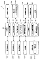
図4は、図3に示す複合機1において同ユーザ優先モードを設定した場合のジョブ出力順の並べ替え動作の一例を示す概念図である。図4における符号41に示す図は、ジョブ識別部23によって識別された、各所定時間内(各時間区分T1、T2、・・・)における時間受付ジョブを、紙面の左側のジョブを先頭側とした受付順に並べたものであり、符号42に示す図は、符号41に示す図における各時間受付ジョブの受付順を、並替部26によって、同ユーザのジョブを優先させて並べ替えたものである(符号41の図を受付状態41といい、符号42の図を並替状態42という)。
FIG. 4 is a conceptual diagram illustrating an example of a job output order rearrangement operation when the same user priority mode is set in the
受付状態41において、符号43に示す位置は時間区分T1の時間計測開始時点であり、符号44に示す位置は時間区分T1の時間計測終了時点及び時間区分T2の時間計測開始時点を示しており、符号45に示す位置は、時間区分T2の時間計測終了時点を示している(ただし、並替状態42におけるT1、T2、・・・は、時間計測が行われていることを示すのではなく、受付状態41における各時間区分に対応するグループであることを示している)。
In the
受付状態41に示すように、或る時間区分T1において、各ユーザからのジョブ(時間受付ジョブ)が符号46に示す第2ジョブを先頭として、第4、第2、第5、第4及び第3ジョブの順番に受け付けられ、また、時間区分T2において、同様に符号47に示す第5ジョブを先頭として、第4、第3、第4及び第1ジョブの順番に受け付けられているとする。ただし、各時間区分T1、T2、・・・において受け付けられるジョブの個数やジョブ(ユーザ)の種類はこの例に限らない(受け付けられたジョブがない場合もある)。
As shown in the
この時間区分T1における時間受付ジョブの中に、同ジョブとして第2ジョブが2つ、第4ジョブが2つ存在し、また時間区分T2における各時間受付ジョブの中に、第4ジョブが2つ存在することが判別され、当該同ジョブ及び上記受付順が考慮され、並替状態42に示すように、時間区分T1では、先頭側から第2ジョブのグループ48、第4ジョブのグループ49、第5ジョブ及び第3ジョブという出力順に並べ替えられ、また、時間区分T2では、第5ジョブ、第4ジョブのグループ50、第3ジョブ及び第1ジョブという出力順に並べ替えられる。
Among the time reception jobs in this time division T1, there are two second jobs and two fourth jobs as the same job, and among the time reception jobs in the time division T2, there are two fourth jobs. As shown in the
ただし、時間区分T1(受付状態41参照)において、受付順において先頭である符号46に示す第2ジョブの後、符号51に示す第4ジョブではなく、符号52に示す第2ジョブが先に符号46の第2ジョブに続けて出力されるように並替状態42においてグループ48が形成される。同様にして、受付順として次の順番である符号51に示す第4ジョブに続いて、符号53に示す第4ジョブが出力されるようにグループ49が形成される。残りの第5ジョブ、第3ジョブは、そのまま受付順の並びとなる。また、時間区分T2においては、受付順において先頭である第5ジョブの後(ここでは当該第5ジョブに対する同ジョブは存在しないため第5ジョブのグループは形成されない)、上記と同様にして同ジョブのグループ50が形成される。残りの第3ジョブ、第1ジョブは同様にそのまま受付順の並びとなる。このようにして、時間区分T1、T2、・・・において受け付けられた時間受付ジョブの並べ替えが行われる。
However, in the time segment T1 (see acceptance state 41), after the second job indicated by
なお、各時間区分T1、T2・・・はいずれも同じ計測時間(例えば上記30秒)が設定されている。また、或る時間区分において同ジョブがない場合もあるが、この場合は当該時間区分における時間受付ジョブの並べ替えは行われず(又は並べ替え動作(処理)は行うが、結果として出力順が並べ替えされていないという構成であってもよい)、受付順のまま出力される。 Note that the same measurement time (for example, the above 30 seconds) is set for each of the time segments T1, T2,. In addition, there is a case where the same job does not exist in a certain time segment. In this case, the time reception job in the time segment is not rearranged (or the rearrangement operation (process) is performed, but the output order is rearranged as a result. The data may be output in the order of acceptance.
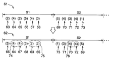
図5は、図3に示す複合機1において近トレイ優先モードを設定した場合のジョブ出力順の並べ替え動作の一例を示す概念図である。図5においても図4と同様、符号61に示す図(受付状態61)は、ジョブ識別部23によって識別された各所定時間内(各時間区分S1、S2、・・・)における時間受付ジョブを、紙面の左側のジョブを先頭側とした受付順に並べたものであり、符号62に示す図(並替状態62)は、受付状態61における各時間受付ジョブの受付順を、並替部26によって、同ジョブ及び排出口517から近い区分トレイに対するジョブの出力を優先させるよう並べ替えたものである。
FIG. 5 is a conceptual diagram illustrating an example of a job output order rearrangement operation when the near tray priority mode is set in the
受付状態61に示すように、或る時間区分S1において、各ユーザからのジョブ(時間受付ジョブ)が符号63に示す第2ジョブを先頭として、それぞれ符号64〜68に示す第4、第2、第5、第4及び第3ジョブの順番に受け付けられ、また、時間区分S2において、同様に符号69に示す第5ジョブを先頭として、それぞれ符号70〜73に示す第4、第3、第4及び第1ジョブの順番に受け付けられているとする。ただし、各時間区分S1、S2、・・・において受け付けられるジョブの個数やジョブの種類はこの例に限らない(受け付けられたジョブがない場合もある)。
As shown in the accepting
まず、時間区分S1における時間受付ジョブの中に、同ジョブとして第2ジョブが2つ、第4ジョブが2つ存在し、また時間区分S2における各時間受付ジョブの中に、第4ジョブが2つ存在することが判別され、当該同ジョブと、排出口517から最も近い位置の区分トレイに対応するジョブと、上記受付順とが考慮され、並替部26によって、並替状態62に示すように並べ替えられる。すなわち、受付状態61における時間受付ジョブの受付順を基に、まず同ジョブを考慮して、上記図4での説明のように同ジョブ同士をグループ化(識別)し、当該グループ化した同ジョブと、同ジョブが存在しない単独の時間受付ジョブとを、それぞれ排出口517から近いトレイに対するものから順に並べ替える。
First, there are two second jobs and two fourth jobs as the same job in the time reception job in the time division S1, and there are two fourth jobs in each time reception job in the time division S2. As shown in the rearranged
時間区分S1においてジョブ(符号63〜68に示す時間受付ジョブ)が受け付けられた時点で、排出口517に対応しているトレイが現在、例えばデフォルト設定としてのメイントレイ531であるとすると、時間区分S1では、先頭側から、まず当該メイントレイ531から近いトレイ(第5トレイ)である符号66に示す第5ジョブ、この第5トレイに近い第4ジョブ(第4トレイ)のグループ74、この第4トレイに近い符号68に示す第3ジョブ(第3トレイ)、この第3トレイに近い第2ジョブ(第2トレイ)のグループ75という出力順に並べ替えられる。時間区分S2では、先頭側から、まず上記時間区分S1での出力順の最後尾であるグループ75である第2ジョブ(第2トレイ)に近いトレイである第1ジョブ(第1トレイ)がきて、次にこの第1トレイから近い第3ジョブ(第3トレイ)、同様に第4ジョブ(第4トレイ)のグループ76、及び第5ジョブという出力順に並べ替えられる。
If a tray corresponding to the
ただし、上記グループ75(第2トレイ)に対して近いトレイとして、時間区分S2における時間受付ジョブにおいては、第1トレイ(第1ジョブ)及び第3トレイ(第3ジョブ)が同じ近さ(距離)であり、いずれも次の排出先トレイとしての候補となるが、ここでは、同じ近さのトレイがある場合には上位位置にあるトレイを優先させるものと設定して、当該第1ジョブを次の出力順として選択している(この逆に下位位置にあるトレイを優先させる設定としてもよい)。このようにして、時間区分S1、S2、・・・において受け付けられた時間受付ジョブの並べ替えが行われる。 However, as a tray close to the group 75 (second tray), in the time reception job in the time section S2, the first tray (first job) and the third tray (third job) are the same closeness (distance). These are all candidates for the next discharge destination tray. Here, if there are trays of the same proximity, the priority is given to the tray in the upper position, and the first job is It is selected as the next output order (conversely, it may be set to give priority to the tray in the lower position). In this way, the time reception jobs received in the time sections S1, S2,... Are rearranged.
なお、各時間区分S1、S2、・・・はいずれも同じ計測時間(例えば上記30秒)が設定されている。また、或る時間区分において同ジョブがない場合もあるが、この場合は上述のように排出口517から近いトレイ順を考慮しての並べ替えのみが行われる。全ての時間受付ジョブが同ジョブである場合には、受付順そのものが出力順となり、並べ替えは行われない。ただし、この場合も同様、並べ替え動作は行うが、結果として出力順が並べ替えされていないという構成であってもよい。
Note that the same measurement time (for example, the above 30 seconds) is set for each of the time segments S1, S2,. Further, there is a case where the same job does not exist in a certain time segment. In this case, rearrangement is performed only in consideration of the tray order closer to the
また、上述のように、或る時間受付ジョブのトレイから同じ近さのトレイとなるジョブが上記第1又は第3ジョブといったように複数存在し、次の出力順としての候補の当該ジョブから選択する必要がある場合、この候補ジョブ以外の(時間区分における)残りの時間受付ジョブも考慮して選択する構成であってもよい。例えば、現在、第3ジョブ(第3トレイ)が出力されており、これに対して例えば第2ジョブ、第4ジョブ、及び第5ジョブの3つの時間受付ジョブの出力順を並べ替える場合、現在の第3トレイから近いトレイの候補として第2又は第4ジョブが候補に上げられるが、この第2ジョブにするか第4ジョブにするかの選択を、残りの第5ジョブを考慮して行ってもよい。この場合、第3ジョブの次に、第2ジョブを選択する方が(出力順が第2、第4、第5ジョブの順となる)、第4ジョブを選択するよりも(出力順が第4、第5、第2ジョブの順となる)、これら第2、4、5ジョブ全ての出力に対するトレイの移動距離が短くて済む。 In addition, as described above, there are a plurality of jobs, such as the first or third job, that are close to the tray of a certain time reception job, and are selected from the candidate jobs as the next output order. In the case where it is necessary to perform this, a configuration may be adopted in which the remaining time receiving jobs (in the time division) other than the candidate jobs are also taken into consideration. For example, when the third job (third tray) is currently output, and the output order of three time reception jobs, for example, the second job, the fourth job, and the fifth job is rearranged, The second or fourth job is raised as a candidate for a tray closer to the third tray of this item. The selection of the second job or the fourth job is performed in consideration of the remaining fifth job. May be. In this case, the second job is selected after the third job (the output order is the second, fourth, and fifth jobs) than the fourth job is selected (the output order is the first). (4, 5 and 2 jobs in this order), and the tray moving distance for the output of all these 2nd, 4th and 5th jobs can be shortened.
図6は、図3に示す複合機1において同ユーザ優先モード又は近トレイ優先モードが設定されている場合のジョブ出力順の並べ替えに関する動作の一例を示すフローチャートである。まず、同ユーザ優先モードが設定される場合について説明する。
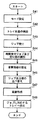
FIG. 6 is a flowchart illustrating an example of operations related to the rearrangement of job output order when the same user priority mode or near tray priority mode is set in the
操作表示部600における同ユーザ優先モードボタンが押下されることによる指示入力情報に基づいて、モード設定部21に同ユーザ優先モードが設定される(ステップS1)。次に、トレイ位置検出部710(トレイ位置判別部27)によって排出口517に対向しているトレイが検出される(ステップS2)。ジョブ受付部22によって各ユーザ(各PC2)からのジョブが受け付けられる(ステップS3)。ジョブ識別部23によって所定時間の計測が行われるとともに、当該所定時間内において上記ステップS3においてジョブ受付部22により受け付けられた時間受付ジョブ、及びこの時間受付ジョブの受付順が識別される(ステップS4)。ジョブ識別部23により識別された時間受付ジョブにおける同ジョブが、同ジョブ判別部24によって判別される(ステップS5)。次に、当該同ジョブを連続して出力させるべく時間受付ジョブの並べ替えを行うための同ユーザ並替情報が並替情報設定部25に設定される(ステップS6)。並替情報設定部25により設定された同ユーザ並替情報、及びジョブ識別部23により識別された受付順情報に基づいて、並替部26によって時間受付ジョブの並べ替えが行われる(ステップS7)。そして、この並べ替えられた時間受付ジョブの順番に画像形成部100によって用紙に対して画像形成が行われ(ステップS8)、各時間受付ジョブに対応するトレイ(区分トレイ)へ当該用紙が排出される(ステップS9)。
Based on the instruction input information when the same user priority mode button on the
次に、近トレイ優先モードが設定される場合について説明する。この場合、まず操作表示部600における近トレイ優先モードボタンが押下されることによる指示入力情報に基づいて、モード設定部21に近トレイ優先モードが設定される(ステップS11)。次に、トレイ位置検出部710(トレイ位置判別部27)によって排出口517に対向しているトレイが検出される(ステップS12)。ジョブ受付部22によって各ユーザ(各PC2)からのジョブが受け付けられる(ステップS13)。ジョブ識別部23によって所定時間の計測が行われるとともに、当該所定時間内において上記ステップS13においてジョブ受付部22により受け付けられた時間受付ジョブ、及びこの時間受付ジョブの受付順が識別される(ステップS14)。ジョブ識別部23により識別された時間受付ジョブにおける同ジョブが、同ジョブ判別部24によって判別される(ステップS15)。次に、当該同ジョブを連続して出力させるべく時間受付ジョブの並べ替えを行うための同ユーザ並替情報と、上記ステップS12においてトレイ位置判別部27によって判別された排出口517に対向しているトレイから、最も近い位置のトレイ(区分トレイ)へ出力させるべく時間受付ジョブを並べ替えるためのトレイ並替情報とが並替情報設定部25に設定される(ステップS16)。並替情報設定部25により設定された同ユーザ並替情報及びトレイ並替情報、並びにジョブ識別部23により識別された受付順情報に基づいて、並替部26によって時間受付ジョブの並べ替えが行われる(ステップS17)。そして、並べ替えられた時間受付ジョブの順番に画像形成部100によって用紙に対する画像形成が行われ(ステップS18)、各時間受付ジョブに対応するトレイへ当該用紙が排出される(ステップS19)。
Next, a case where the near tray priority mode is set will be described. In this case, first, the near tray priority mode is set in the
(第2実施形態)
図7は、本発明の第2の実施形態に係る画像形成装置の一例である複合機1aの概略構
成を示すブロック図である。図7における複合機1aと、図3における複合機1とでは下記の点で異なる。すなわち、複合機1aでは、制御部20にモード設定部21a、枚数判別部24a、並替情報設定部25a及び並替部26aを備えた構成となっている。その他の構成は図3に示す複合機1と同様でありその説明を省略する。
(Second Embodiment)
FIG. 7 is a block diagram showing a schematic configuration of a
モード設定部21aは、枚数優先モードを設定するものである。枚数優先モードとは、ジョブ受付部22に受け付けられた時間受付ジョブに対し、出力用紙枚数が少ないものから順に優先させるように並べ替えて出力させるモードである。なお、モード設定部21aに対するこの枚数優先モードの設定は、例えば操作表示部600の表示器603に表示された枚数優先モードボタン(図略)等の押下による指示入力情報に基づいて行われる。
The
枚数判別部24aは、ジョブ識別部23によって識別された時間受付ジョブにおける、当該各時間受付ジョブ(の出力)に対する用紙の枚数(出力用紙枚数)を判別するものである。
The sheet
並替情報設定部25aは、出力用紙枚数の少ない時間受付ジョブから出力させるべく時間受付ジョブの並べ替えを行う並替情報(この並替情報を枚数並替情報という)を設定するものである。並替部26aは、並替情報設定部25aによって設定された枚数並替情報、及びジョブ識別部23によって識別された受付順情報に基づいて、時間受付ジョブの出力順の並べ替えを行うものである。
The rearrangement information setting unit 25a sets rearrangement information (this rearrangement information is referred to as “number rearrangement information”) for rearranging time reception jobs so as to be output from a time reception job with a small number of output sheets. The
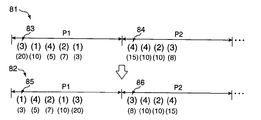
ここで、枚数優先モードを設定した場合のジョブの並べ替え動作について、図8を用いて説明する。図8は、図7に示す複合機1aにおいて枚数優先モードを設定した場合のジョブの並べ替え動作の一例を示す概念図である。符号81に示す図(受付状態81)は、図4、5と同様にジョブ識別部23によって識別された各所定時間内(各時間区分P1、P2、・・・)における時間受付ジョブを、紙面の左側のジョブを先頭側とした受付順に並べたものであり、符号82に示す図(並替状態82)は、受付状態81における各時間受付ジョブの受付順を、並替部26aによって、出力用紙枚数の少ない時間受付ジョブの出力を優先させて並べ替えたものである。
Here, the job rearrangement operation when the number priority mode is set will be described with reference to FIG. FIG. 8 is a conceptual diagram showing an example of job rearrangement operation when the number priority mode is set in the
受付状態81に示すように、或る時間区分P1において、各ユーザからのジョブ(時間受付ジョブ)が符号83に示す第3ジョブを先頭として、第1、第4、第2及び第1ジョブの順番に受け付けられ、また、時間区分P2において、同様に符号84に示す第4ジョブを先頭として、第4、第2及び第3ジョブの順番に受け付けられているとする(下側の括弧内の数字は後述の出力用紙枚数を示している)。ただし、各時間区分P1、P2、・・・において受け付けられるジョブの個数やジョブ(ユーザ)の種類はこの例に限らない(受け付けられたジョブがない場合もある)。
As shown in the
枚数判別部24aによって、時間区分P1における各時間受付ジョブの出力用紙枚数が判別され、ここでは、時間区分P1では先頭側から順に、第3ジョブが例えば20枚、同様に第1ジョブが10枚、第4ジョブが5枚、第2ジョブが7枚、第1ジョブが3枚と判別され、また、時間区分P2では、先頭側から順に各第4ジョブが15枚、10枚、第2ジョブが10枚、第3ジョブが8枚と判別される。そして、この出力用紙枚数及び上記受付順が考慮され、並替部26aによって並替状態82に示すように、時間区分P1では、用紙出力枚数の少ないものから順に、符号85に示す第1ジョブを先頭に、第4、第2、第1及び第3ジョブという出力順に並べ替えられ、また、時間区分P2では、符号86に示す第3ジョブを先頭に、第4、第2及び第4ジョブという出力順に並べ替えられる。このようにして、時間区分P1、P2、・・・において受け付けられた時間受付ジョブの並べ替えが行われる。
The
なお、各時間区分P1、P2・・・はいずれも同じ計測時間(例えば上記30秒)が設定されている。また、或る時間区分において同じ出力用紙枚数である時間受付ジョブが存在する場合もあるが、この場合、当該同じ出力用紙枚数の時間受付ジョブ同士間の並べ替えは行われず(又は並べ替え動作(処理)は行うが、結果として出力順が並べ替えされていないという構成であってもよい)、これらの受付順のまま出力される。 Note that the same measurement time (for example, the above 30 seconds) is set for each of the time sections P1, P2,. In addition, there may be time reception jobs having the same number of output sheets in a certain time segment. In this case, the time reception jobs having the same number of output sheets are not rearranged (or rearrangement operation ( (The processing may be performed but the output order may not be rearranged as a result).
図9は、図7に示す複合機1aにおいて枚数優先モードが設定されている場合のジョブ出力順の並べ替えに関する動作の一例を示すフローチャートである。操作表示部600における枚数優先モードボタンが押下されることによる指示入力情報に基づいて、モード設定部21aに枚数優先モードが設定される(ステップS21)。次に、トレイ位置検出部710(トレイ位置判別部27)によって排出口517に対向しているトレイが検出される(ステップS22)。ジョブ受付部22によって各ユーザ(各PC2)からのジョブが受け付けられる(ステップS23)。ジョブ識別部23によって所定時間の計測が行われるとともに、当該所定時間内において上記ステップS23においてジョブ受付部22により受け付けられた時間受付ジョブ、及びこの時間受付ジョブの受付順が識別される(ステップS24)。枚数判別部24aによって、各時間区分における各時間受付ジョブの出力用紙枚数が判別され(ステップS25)、並替情報設定部25aによって、出力用紙枚数の少ない時間受付ジョブから出力させるべく時間受付ジョブの並べ替えを行う枚数並替情報が設定される(ステップS26)。そして、並替情報設定部25aにより設定された枚数並替情報、及びジョブ識別部23により識別された受付順情報に基づいて、並替部26aによって時間受付ジョブの並べ替えが行われる(ステップS27)。そして、この並べ替えられた時間受付ジョブの順番に画像形成部100によって用紙に対して画像形成が行われ(ステップS28)、各時間受付ジョブに対応するトレイ(区分トレイ)へ当該用紙が排出される(ステップS29)。
FIG. 9 is a flowchart illustrating an example of the operation related to the rearrangement of the job output order when the number priority mode is set in the multifunction peripheral 1a illustrated in FIG. Based on the instruction input information when the number priority mode button on the
(第3実施形態)
図10は、本発明の第3の実施形態に係る画像形成装置の一例である複合機1bの概略構成を示すブロック図である。図10における複合機1bと、図3における複合機1とでは下記の点で異なる。すなわち、複合機1bでは、制御部20にモード設定部21b、並替情報設定部25b及び並替部26bを備え、同ジョブ判別部24がない構成となっている。その他の構成は図3に示す複合機1と同様でありその説明を省略する。
(Third embodiment)
FIG. 10 is a block diagram illustrating a schematic configuration of a multifunction peripheral 1b which is an example of an image forming apparatus according to the third embodiment of the present invention. The multifunction device 1b in FIG. 10 differs from the
モード設定部21bは、出力順固定モードを設定するものである。出力順固定モードとは、ジョブ受付部22に受け付けられた時間受付ジョブに対し、固定された所定の出力順、すなわち、本実施形態では、各トレイのうちの一のトレイに対して、遠い位置のトレイから順に出力させるという固定された出力順に並べ替えて出力させるモードである。なお、モード設定部21bに対するこの出力順固定モードの設定は、例えば操作表示部600の表示器603に表示された出力順固定モードボタン(図略)等の押下による指示入力情報に基づいて行われる。
The
並替情報設定部25bは、上記固定された所定の出力順に出力させるべく時間受付ジョブの並べ替えを行う並替情報(この並替情報を固定並替情報という)を設定するものである。なお、この固定並替情報を例えば制御部20の所定の場所に予め(デフォルト値として)記憶しておき、並替情報設定部25bは、モード設定部21bに出力順固定モードが設定された時点で、この記憶されている固定並替情報を用いて当該固定並替情報の設定を行ってもよい。なお、本実施形態では、上記各トレイを、多段トレイ551(各区分トレイ)及びメイントレイ531とし、上記一のトレイをデフォルトとして排出口517に対向するトレイとして設定されているメイントレイ531とする。
The rearrangement
並替部26bは、並替情報設定部25bによって設定された固定並替情報、及びジョブ識別部23によって識別された受付順情報に基づいて、時間受付ジョブの出力順の並べ替えを行うものである。
The
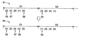
ここで、出力順固定モードを設定した場合のジョブの並べ替え動作について、図11を用いて説明する。図11は、図10に示す複合機1bにおいて出力順固定モードを設定した場合のジョブの並べ替え動作の一例を示す概念図である。符号91に示す図(受付状態91)は、図4、5と同様にジョブ識別部23によって識別された各所定時間内(各時間区分Q1、Q2、・・・)における時間受付ジョブを、紙面の左側のジョブを先頭側とした受付順に並べたものであり、符号92に示す図(並替状態92)は、受付状態91における各時間受付ジョブの受付順を、並替部26bによって、メイントレイ531に対して、遠い位置のトレイ(区分トレイ)から順に出力させるという固定された出力順(固定順)に並べ替えたものである。
Here, the job rearrangement operation when the output order fixed mode is set will be described with reference to FIG. FIG. 11 is a conceptual diagram illustrating an example of a job rearrangement operation when the output order fixed mode is set in the multifunction peripheral 1b illustrated in FIG. A diagram 91 (acceptance state 91) shows a time acceptance job within each predetermined time (each time segment Q1, Q2,...) Identified by the
受付状態91に示すように、或る時間区分Q1において、各ユーザからのジョブ(時間受付ジョブ)が符号93に示す第2ジョブを先頭として、第4、第5、第1及び第4ジョブの順番に受け付けられ、また、時間区分Q2において、同様に符号94に示す第3ジョブを先頭として、第2、第4及び第1ジョブの順番に受け付けられているとする。ただし、各時間区分Q1、Q2、・・・において受け付けられるジョブの個数やジョブの種類はこの例に限らない(受け付けられたジョブがない場合もある)。
As shown in the
この出力用紙枚数及び上記受付順が考慮され、並替部26bによって並替状態92に示すように、時間区分Q1では、メイントレイ531からより遠い区分トレイから順に、符号95に示す第1ジョブを先頭に、第2、第4、第4及び第5ジョブという出力順に並べ替えられ、また、時間区分Q2では、符号96に示す第1ジョブを先頭に、第2、第3、及び第4ジョブという出力順に並べ替えられる。このようにして、時間区分Q1、Q2、・・・において受け付けられた時間受付ジョブの並べ替えが行われる。ただし、並べ替えが行われる際、同じユーザからのジョブがある場合には、この同じユーザのジョブは、それぞれ受け付けられた順番に並べられる。ここでは、受付状態91において、符号97に示す第4ジョブ、符号98に示す第4ジョブの順に受け付けられているが、これらが並替状態92において並べ替えられるときにも当該順番に従って並べられる。
In consideration of the number of output sheets and the above order of acceptance, as shown in the
なお、各時間区分Q1、Q2・・・はいずれも同じ計測時間(例えば上記30秒)が設定されている。また、或る時間区分において時間受付ジョブの受付順が既に当該固定順になっている場合もあるが、この場合、時間受付ジョブの並べ替えは行われず(又は並べ替え動作(処理)は行うが、結果として出力順が並べ替えされていないという構成であってもよい)、この受付順のまま出力される。 Note that the same measurement time (for example, the above 30 seconds) is set for each of the time segments Q1, Q2,. In some cases, the reception order of time reception jobs is already in the fixed order in this time segment. In this case, the time reception jobs are not rearranged (or rearrangement operation (processing) is performed). As a result, the output order may not be rearranged), and the output order is output.
図12は、図10に示す複合機1bにおいて出力順固定モードが設定されている場合のジョブ出力順の並べ替えに関する動作の一例を示すフローチャートである。操作表示部600における出力順固定モードボタンが押下されることによる指示入力情報に基づいて、モード設定部21bに出力順固定モードが設定される(ステップS41)。次に、トレイ位置検出部710(トレイ位置判別部27)によって排出口517に対向しているトレイが検出される(ステップS42)。ジョブ受付部22によって各ユーザ(各PC2)からのジョブが受け付けられる(ステップS43)。ジョブ識別部23によって所定時間の計測が行われるとともに、当該所定時間内において上記ステップS43においてジョブ受付部22により受け付けられた時間受付ジョブ、及びこの時間受付ジョブの受付順が識別される(ステップS44)。並替情報設定部25bによって、メイントレイ531に対して遠い位置の区分トレイから順に出力させる固定の出力順に出力させるべく時間受付ジョブの並べ替えを行う固定並替情報が設定される(ステップS45)。そして、並替情報設定部25bにより設定された固定並替情報、及びジョブ識別部23により識別された受付順情報に基づいて、並替部26bによって時間受付ジョブの並べ替えが行われる(ステップS46)。そして、この並べ替えられた時間受付ジョブの順番に画像形成部100によって用紙に対して画像形成が行われ(ステップS47)、各時間受付ジョブに対応するトレイ(区分トレイ)へ当該用紙が排出される(ステップS48)。
FIG. 12 is a flowchart illustrating an example of an operation related to the rearrangement of the job output order when the output order fixed mode is set in the multifunction peripheral 1b illustrated in FIG. Based on the instruction input information by pressing the output order fixing mode button in the
以上のように本発明の画像形成装置によれば、所定時間内にジョブ受付部22により受け付けられた時間受付ジョブと、当該時間受付ジョブの受付順とがジョブ識別部23によって識別され、並替情報設定部25により設定された並替情報と、ジョブ識別部23により識別された時間受付ジョブの受付順の情報とに基づいて、並替部26によって時間受付ジョブの出力順の並べ替えが行われるため、ジョブの出力が受付順に固定されることなく、すなわち、ジョブの受付順に従ってトレイが移動されてしまい、場合によっては不必要な昇降移動が繰り返されてしまうといったことなく、各ユーザのジョブの出力を効率良く行うことができる。
As described above, according to the image forming apparatus of the present invention, the time reception job received by the
また、時間受付ジョブにおける同じユーザのジョブが同ジョブ判別部24によって判別され、同ユーザ並替情報と、時間受付ジョブの受付順の情報とに基づいて、並替部26によって時間受付ジョブの出力順の並べ替えが行われるため、時間受付ジョブのうちの同じユーザのジョブを続けて(連続させて)出力されることが可能となり、トレイを昇降移動させる時間を短縮する(トレイの昇降移動(回数)を低減させる)ことができる。
The job of the same user in the time reception job is determined by the
また、トレイ位置検出部710(トレイ位置センサ705、706)による検出情報に基づいて排出口517に近い位置にあるトレイがトレイ位置判別部27によって判別され、同ユーザ並替情報及びトレイ並替情報と、時間受付ジョブの受付順の情報とに基づいて、並替部26によって時間受付ジョブの出力順の並べ替えが行われるため、同じユーザのジョブを続けて出力することができるとともに、排出口517により近い位置のトレイから順に出力(排出)させることができ、トレイを昇降移動させる時間をより短縮することができる。
In addition, the tray
また、時間受付ジョブにおける出力用紙枚数が枚数判別部24aによって判別され、枚数並替情報と、時間受付ジョブの受付順の情報とに基づいて、並替部26aによって時間受付ジョブの出力順の並べ替えが行われるため、所定時間内に受け付けられたジョブの出力用紙枚数を考慮して出力させることが可能となり、すなわち、例えば少ない出力用紙枚数のジョブから順に出力させたり、あるいは多い出力用紙枚数のジョブから順に出力させたりすることが可能となり、ひいては各ユーザのジョブの出力を効率良く行うことができる。
Further, the number of output sheets in the time reception job is determined by the sheet
また、並替情報設定部25aに出力用紙枚数の少ない時間受付ジョブから出力させるべく時間受付ジョブの並べ替えを行う枚数並替情報が設定されるため、出力用紙枚数の少ないジョブから順に出力させることができ、或るユーザによる出力用紙枚数が多いジョブの出力によって、少枚数のジョブを出力を行おうとしているユーザが長時間待たされるといったことをなくすことができ、ひいては各ユーザのジョブの出力を効率良く行うことができる。 Further, since the sheet number rearrangement information for rearranging the time reception jobs is set in the rearrangement information setting unit 25a so as to output from the time reception job with the smaller number of output sheets, the jobs are output in order from the job with the smaller number of output sheets. It is possible to prevent a user trying to output a small number of jobs from waiting for a long time by outputting a job with a large number of output sheets by a certain user. It can be done efficiently.
また、固定された所定の出力順に出力させるべく時間受付ジョブの並べ替えを行う固定並替情報が並替情報設定部25bによって設定され、この固定並替情報と、時間受付ジョブの受付順の情報とに基づいて、並替部26bによって時間受付ジョブの出力順の並べ替えが行われるため、同じユーザからのジョブであるか、あるいはジョブの枚数が何枚であるかなどといった判別動作(制御)を行う必要がなく、より簡易な構成で、或る固定された(予め設定された)出力順、例えば最上位置又は最下位置のトレイから順に隣のトレイに出力させていくといったことが可能となり、ひいては効率良いジョブの出力が可能となる。
In addition, fixed rearrangement information for rearranging the time reception jobs to be output in a fixed predetermined output order is set by the rearrangement
さらに、並替情報設定部25bに各トレイのうちの一のトレイに対して遠い位置のトレイから順に出力させるべく時間受付ジョブの並べ替えを行う固定並替情報が設定されるため、各トレイのうちの一のトレイ、例えばデフォルトの出力先として設定されているメイントレイ531に対し、遠い位置のトレイ(区分トレイ551a〜551e)に対応したジョブから順に出力させ、メイントレイ531に対してより近い位置の区分トレイにおいてジョブの出力を終了させることが可能となり、メイントレイ531を排出口517の位置(ホームポジション)まで戻すためのトレイの移動時間を短縮することができる。すなわち、ジョブ出力を行うべくトレイの昇降移動を行い、出力終了後にもさらにメイントレイ531をホームポジションに戻すべく、場合によっては長い距離を移動させるといったことが不要となる。なお、本発明は以下の態様をとることができる。
Further, since the reordering
(A)図4における時間区分T1、T2、・・・は互いに異なる時間であってもよい。図5、8及び11における時間区分も同様である。 (A) The time sections T1, T2,... In FIG. The same applies to the time segments in FIGS.
(B)或る時間区分において複数の例えば5つのジョブが受け付けられ、並替部26により出力順が(1〜5番目に)並べ替えられ、受付順の先頭から順にジョブ(時間受付ジョブ)の出力がなされて、途中のジョブ、例えば3番目のジョブが出力されているときに(又は出力終了時点で)、新たに別のジョブが受け付けられた場合、ジョブ識別部23は、残りの4番目及び5番目のジョブ出力順の並べ替え状態をリセットするとともに、このリセットした時点から新たに所定時間(時間区分)の計測を開始し、当該時間区分内に受け付けられたジョブと上記残りの4、5番目のジョブとを用いて再度出力順の並べ替えを行う構成であってもよい。この場合、新たに別のジョブが受け付けられたとしても直ぐに先の出力順をリセットするのではなく、上記1〜5番目のジョブのうちの所定番目のジョブまでは必ず出力させ、この所定番目のジョブの出力の終了を待って当該リセット及び時間計測を開始する構成としてもよい。
(B) A plurality of, for example, five jobs are received in a certain time segment, the output order is rearranged (first to fifth) by the
(C)排出先としてのトレイは、上記各実施形態に示すようにメイントレイ531及び多段トレイ551といった上下2部からなる構成でなくともよく、例えば上部、中部、下部といった3部からなるトレイ構成、あるいはそれ以上の部数からなるトレイ構成であってもよい。また、多段トレイ551の段数も5段に限らず、例えば4段以下又は6段以上で構成されていてもよい。
(C) The tray as the discharge destination does not have to be configured with two upper and lower parts such as the
1、1a、1b 複合機(画像形成装置)
2 PC
20 制御部
21、21a、21b モード設定部
22 ジョブ受付部(受付手段)
23 ジョブ識別部(識別手段)
24 同ジョブ判別部(ジョブ判別手段)
24a 枚数判別部(枚数判別手段)
25、25a、25b 並替情報設定部(設定手段)
26、26a、26b 並替部(並替手段)
27 トレイ位置判別部(トレイ判別手段)
28 駆動制御部
100 画像形成部
500 後処理部
517 排出口(用紙排出口)
530 下部シート積載装置
531 メイントレイ(トレイ)
550 上部シート積載装置
551 多段トレイ
551a〜551e 区分トレイ(トレイ)
570 トレイ駆動部
600 操作表示部
700 検出部
705、706 トレイ位置センサ(トレイ検出手段)
710 トレイ位置検出部(トレイ検出手段)
1, 1a, 1b MFP (image forming device)
2 PC
20
23 Job identification part (identification means)
24 Job discrimination section (job discrimination means)
24a Number discriminating section (number discriminating means)
25, 25a, 25b Rearrangement information setting unit (setting means)
26, 26a, 26b Rearrangement unit (rearrangement means)
27 Tray position determination unit (tray determination means)
28
530 Lower
550
570
710 Tray position detection unit (tray detection means)
Claims (7)
前記ジョブを受け付ける受付手段と、
所定時間の計測を行うとともに、所定時間内において前記受付手段によって受け付けられた時間受付ジョブ及び当該時間受付ジョブの受付順を識別する識別手段と、
時間受付ジョブの出力順の並べ替えを行うための所定の条件を示す並替情報を設定する設定手段と、
前記設定手段によって設定された並替情報と、前記識別手段によって識別された受付順の情報とに基づいて、時間受付ジョブの出力順の並べ替えを行う並替手段とを備えることを特徴とする画像形成装置。 An image forming apparatus that includes a plurality of trays from which paper is discharged, and that can selectively face the paper discharge port in correspondence with each user's job.
Receiving means for receiving the job;
An identification means for measuring a predetermined time and identifying a time reception job received by the reception means within a predetermined time and a reception order of the time reception job;
Setting means for setting rearrangement information indicating a predetermined condition for rearranging the output order of the time reception job;
Reordering means for reordering the output order of time reception jobs based on the reordering information set by the setting means and the information on the order of acceptance identified by the identification means; Image forming apparatus.
前記設定手段は、ジョブ判別手段によって判別された同じユーザのジョブを続けて出力させるべく時間受付ジョブの並べ替えを行う同ユーザ並替情報を設定し、
前記並替手段は、前記設定手段によって設定された同ユーザ並替情報と、前記受付順の情報とに基づいて、時間受付ジョブの出力順の並べ替えを行うことを特徴とする請求項1記載の画像形成装置。 Job discrimination means for discriminating a job of the same user in the time reception job identified by the identification means;
The setting means sets the same user rearrangement information for rearranging the time reception job so as to continuously output the job of the same user determined by the job determination means,
2. The rearrangement unit rearranges the output order of time reception jobs based on the same user rearrangement information set by the setting unit and the reception order information. Image forming apparatus.
前記トレイ検出手段による検出情報に基づいて、用紙排出口に近い位置にあるトレイを判別するトレイ判別手段とをさらに備え、
前記設定手段は、トレイ判別手段によって判別された近い位置のトレイに出力させるべく時間受付ジョブの並べ替えを行うトレイ並替情報をさらに設定し、
前記並替手段は、前記設定手段によって設定された前記同ユーザ並替情報及びトレイ並替情報と、前記受付順の情報とに基づいて、時間受付ジョブの出力順の並べ替えを行うことを特徴とする請求項2記載の画像形成装置。 Tray detection means for detecting which tray faces the paper discharge port;
A tray discriminating unit for discriminating a tray located near the paper discharge port based on detection information by the tray detection unit;
The setting means further sets tray rearrangement information for rearranging time reception jobs to be output to a tray at a close position determined by the tray determination means,
The rearranging means rearranges the output order of time reception jobs based on the same user rearrangement information and tray rearrangement information set by the setting means, and the reception order information. The image forming apparatus according to claim 2.
前記設定手段は、枚数判別手段によって判別された出力用紙枚数に基づいて時間受付ジョブの並べ替えを行う枚数並替情報を設定し、
前記並替手段は、前記設定手段によって設定された枚数並替情報と、前記受付順の情報とに基づいて、時間受付ジョブの出力順の並べ替えを行うことを特徴とする請求項1記載の画像形成装置。 A sheet number determining means for determining the number of output sheets in the time reception job identified by the identifying means;
The setting unit sets sheet number rearrangement information for rearranging time reception jobs based on the number of output sheets determined by the sheet number determination unit;
The said rearrangement means rearranges the output order of time reception jobs based on the number rearrangement information set by the setting means and the information on the reception order. Image forming apparatus.
前記並替手段は、前記設定手段によって設定された固定並替情報と、前記受付順の情報とに基づいて、時間受付ジョブの出力順の並べ替えを行うことを特徴とする請求項1記載の画像形成装置。 The setting means sets fixed rearrangement information for rearranging time reception jobs to be output in a fixed predetermined output order,
The said rearrangement means rearranges the output order of a time reception job based on the fixed rearrangement information set by the said setting means, and the information of the said reception order. Image forming apparatus.
Priority Applications (1)
| Application Number | Priority Date | Filing Date | Title |
|---|---|---|---|
| JP2004115375A JP2005297313A (en) | 2004-04-09 | 2004-04-09 | Image forming apparatus |
Applications Claiming Priority (1)
| Application Number | Priority Date | Filing Date | Title |
|---|---|---|---|
| JP2004115375A JP2005297313A (en) | 2004-04-09 | 2004-04-09 | Image forming apparatus |
Publications (1)
| Publication Number | Publication Date |
|---|---|
| JP2005297313A true JP2005297313A (en) | 2005-10-27 |
Family
ID=35329456
Family Applications (1)
| Application Number | Title | Priority Date | Filing Date |
|---|---|---|---|
| JP2004115375A Pending JP2005297313A (en) | 2004-04-09 | 2004-04-09 | Image forming apparatus |
Country Status (1)
| Country | Link |
|---|---|
| JP (1) | JP2005297313A (en) |
Cited By (4)
| Publication number | Priority date | Publication date | Assignee | Title |
|---|---|---|---|---|
| JP2009139731A (en) * | 2007-12-07 | 2009-06-25 | Kyocera Mita Corp | Image forming apparatus and image forming method |
| JP2013097257A (en) * | 2011-11-02 | 2013-05-20 | Konica Minolta Business Technologies Inc | Image forming apparatus |
| JP2013148944A (en) * | 2012-01-17 | 2013-08-01 | Seiko Epson Corp | Print control server, and printing method |
| JP2019171774A (en) * | 2018-03-29 | 2019-10-10 | 京セラドキュメントソリューションズ株式会社 | Image formation apparatus and print control system |
Citations (5)
| Publication number | Priority date | Publication date | Assignee | Title |
|---|---|---|---|---|
| JPH03149617A (en) * | 1989-11-06 | 1991-06-26 | Canon Inc | Printer controller |
| JPH0516320U (en) * | 1991-08-23 | 1993-03-02 | 株式会社東芝 | Print control method of page printer |
| JPH11292390A (en) * | 1998-04-13 | 1999-10-26 | Canon Inc | Printing equipment |
| JPH11322183A (en) * | 1998-05-14 | 1999-11-24 | Canon Inc | Printing device with multiple output bins |
| JP2000305421A (en) * | 1999-04-21 | 2000-11-02 | Konica Corp | Image forming device |
-
2004
- 2004-04-09 JP JP2004115375A patent/JP2005297313A/en active Pending
Patent Citations (5)
| Publication number | Priority date | Publication date | Assignee | Title |
|---|---|---|---|---|
| JPH03149617A (en) * | 1989-11-06 | 1991-06-26 | Canon Inc | Printer controller |
| JPH0516320U (en) * | 1991-08-23 | 1993-03-02 | 株式会社東芝 | Print control method of page printer |
| JPH11292390A (en) * | 1998-04-13 | 1999-10-26 | Canon Inc | Printing equipment |
| JPH11322183A (en) * | 1998-05-14 | 1999-11-24 | Canon Inc | Printing device with multiple output bins |
| JP2000305421A (en) * | 1999-04-21 | 2000-11-02 | Konica Corp | Image forming device |
Cited By (5)
| Publication number | Priority date | Publication date | Assignee | Title |
|---|---|---|---|---|
| JP2009139731A (en) * | 2007-12-07 | 2009-06-25 | Kyocera Mita Corp | Image forming apparatus and image forming method |
| JP2013097257A (en) * | 2011-11-02 | 2013-05-20 | Konica Minolta Business Technologies Inc | Image forming apparatus |
| US8922799B2 (en) | 2011-11-02 | 2014-12-30 | Konica Minolta Business Technologies, Inc. | Image forming apparatus |
| JP2013148944A (en) * | 2012-01-17 | 2013-08-01 | Seiko Epson Corp | Print control server, and printing method |
| JP2019171774A (en) * | 2018-03-29 | 2019-10-10 | 京セラドキュメントソリューションズ株式会社 | Image formation apparatus and print control system |
Similar Documents
| Publication | Publication Date | Title |
|---|---|---|
| CN101526768A (en) | Post-processing apparatus | |
| JP4287232B2 (en) | Stapling apparatus and image forming apparatus | |
| JP4123204B2 (en) | Paper post-processing apparatus and control method thereof | |
| JP2005297313A (en) | Image forming apparatus | |
| JP3416689B2 (en) | Image forming system, image forming system control method, and sheet processing apparatus | |
| JP5150269B2 (en) | Image forming system | |
| JP5481539B2 (en) | Image forming system | |
| JP4086874B2 (en) | Sheet processing apparatus and image forming apparatus | |
| JP3330325B2 (en) | Paper post-processing apparatus and image forming apparatus provided with paper post-processing apparatus | |
| JP2000177921A (en) | Post-processing device and post-processing method | |
| JP3924514B2 (en) | Image forming apparatus | |
| JP2005156876A (en) | Image forming apparatus | |
| JP4023242B2 (en) | Sheet post-processing apparatus and image forming apparatus | |
| JP2007062866A (en) | Sheet processing device | |
| JP2756340B2 (en) | Sheet sorting device | |
| JP3682190B2 (en) | Image forming apparatus | |
| JP2925263B2 (en) | Image forming apparatus with automatic document feeder | |
| JP2006117335A (en) | Postprocessing device and image forming device equipped with it | |
| JP2024126160A (en) | Image forming apparatus, processing condition setting method, and processing condition setting program | |
| JPH06199468A (en) | Copying device | |
| JP2000034051A (en) | Paper postprocessor and image forming device therewith | |
| JP3182132B2 (en) | Image forming system | |
| JP2003252516A (en) | Sheet handling device and image forming device | |
| JP2001130826A (en) | Imaging device | |
| JPH11157169A (en) | Image forming apparatus having 2 in 1 mode |
Legal Events
| Date | Code | Title | Description |
|---|---|---|---|
| A621 | Written request for application examination |
Free format text: JAPANESE INTERMEDIATE CODE: A621 Effective date: 20070327 |
|
| A131 | Notification of reasons for refusal |
Free format text: JAPANESE INTERMEDIATE CODE: A131 Effective date: 20091222 |
|
| A02 | Decision of refusal |
Free format text: JAPANESE INTERMEDIATE CODE: A02 Effective date: 20100413 |