JP2005297218A - System for monitoring mold for molding machine - Google Patents
System for monitoring mold for molding machine Download PDFInfo
- Publication number
- JP2005297218A JP2005297218A JP2004112475A JP2004112475A JP2005297218A JP 2005297218 A JP2005297218 A JP 2005297218A JP 2004112475 A JP2004112475 A JP 2004112475A JP 2004112475 A JP2004112475 A JP 2004112475A JP 2005297218 A JP2005297218 A JP 2005297218A
- Authority
- JP
- Japan
- Prior art keywords
- molding machine
- image
- mold
- machine controller
- monitoring camera
- Prior art date
- Legal status (The legal status is an assumption and is not a legal conclusion. Google has not performed a legal analysis and makes no representation as to the accuracy of the status listed.)
- Granted
Links
- 238000012544 monitoring process Methods 0.000 title claims abstract description 100
- 238000000465 moulding Methods 0.000 title claims abstract description 88
- 238000012545 processing Methods 0.000 claims abstract description 74
- 230000002159 abnormal effect Effects 0.000 claims abstract description 23
- 230000005856 abnormality Effects 0.000 claims description 19
- 238000004891 communication Methods 0.000 claims description 16
- 230000006870 function Effects 0.000 claims description 15
- 238000013500 data storage Methods 0.000 claims description 8
- 230000009467 reduction Effects 0.000 abstract description 5
- 238000001746 injection moulding Methods 0.000 description 21
- 108700028516 Lan-7 Proteins 0.000 description 14
- 238000003384 imaging method Methods 0.000 description 14
- 238000000034 method Methods 0.000 description 12
- 230000008569 process Effects 0.000 description 6
- 230000008859 change Effects 0.000 description 5
- 238000004458 analytical method Methods 0.000 description 3
- 230000007547 defect Effects 0.000 description 3
- 230000007246 mechanism Effects 0.000 description 3
- 239000002184 metal Substances 0.000 description 3
- 230000003287 optical effect Effects 0.000 description 3
- 238000003672 processing method Methods 0.000 description 3
- 230000004044 response Effects 0.000 description 3
- 230000000694 effects Effects 0.000 description 2
- 230000006872 improvement Effects 0.000 description 2
- 238000002347 injection Methods 0.000 description 2
- 239000007924 injection Substances 0.000 description 2
- 238000009434 installation Methods 0.000 description 2
- 230000007257 malfunction Effects 0.000 description 2
- 239000000758 substrate Substances 0.000 description 2
- 230000005540 biological transmission Effects 0.000 description 1
- 230000000903 blocking effect Effects 0.000 description 1
- 238000001816 cooling Methods 0.000 description 1
- 230000002950 deficient Effects 0.000 description 1
- 238000001514 detection method Methods 0.000 description 1
- 238000011161 development Methods 0.000 description 1
- 238000010586 diagram Methods 0.000 description 1
- 238000005429 filling process Methods 0.000 description 1
- 239000004973 liquid crystal related substance Substances 0.000 description 1
- 238000007726 management method Methods 0.000 description 1
- 239000000463 material Substances 0.000 description 1
- 238000005498 polishing Methods 0.000 description 1
Images


Landscapes
- Moulds For Moulding Plastics Or The Like (AREA)
- Injection Moulding Of Plastics Or The Like (AREA)
Abstract
Description
本発明は、型開きした金型のキャビティ部位をイメージセンサにより撮像し、画像処理によりキャビティ部位の状態を判別する成形機の金型監視システムに関する。 The present invention relates to a mold monitoring system for a molding machine that takes an image of a cavity part of an opened mold by an image sensor and discriminates the state of the cavity part by image processing.
従来、成形機の金型に残留する成形品の有無等を監視するため、型開きした金型のキャビティ部位をイメージセンサ(カメラ)により撮像するとともに、画像処理によりキャビティ部位の状態を判別するようにした金型監視システムとしては、特開2002−166457号公報で開示される射出成形機が知られている。 Conventionally, in order to monitor the presence or absence of a molded product remaining in a mold of a molding machine, an image sensor (camera) is used to image the cavity portion of the opened mold, and the state of the cavity portion is determined by image processing. As such a mold monitoring system, an injection molding machine disclosed in Japanese Patent Laid-Open No. 2002-166457 is known.
同公報で開示される射出成形機(金型監視システム)は、成形条件及び監視条件を設定するための操作部と、成形条件に基づいて成形を行うシーケンスコントロール部と、金型装置を撮影する撮像手段と、成形条件及び金型装置のモニタ画像を表示するための表示部と、金型装置の状態を表す信号及び監視条件に基づいて金型装置に異常が発生したかどうかを判断する画像処理部を備え、これにより、金型監視部と射出成形機を一体にし、別の金型監視部を設置するスペースを不要にしたものである。
しかし、上述した金型監視部を一体にした従来の射出成形機は、次のような問題点があった。 However, the conventional injection molding machine in which the above-described mold monitoring unit is integrated has the following problems.
第一に、カメラ(撮像手段)から得る画像信号を成形機コントローラに付与し、この成形機コントローラにより画像処理を含む全処理を行うため、成形機コントローラにおける処理の負担がかなり大きくなる。特に、画像処理の場合、データ量の多いイメージデータを扱うことから、成形機コントローラによる成形機本体に対する本来の制御に遅れ等の支障を生じる虞れがある。 First, since an image signal obtained from a camera (imaging means) is applied to the molding machine controller and all processes including image processing are performed by the molding machine controller, the processing load on the molding machine controller is considerably increased. In particular, in the case of image processing, since image data with a large amount of data is handled, there is a possibility that troubles such as delay may occur in the original control of the molding machine main body by the molding machine controller.
第二に、カメラを高性能カメラ等に変更し、この変更に伴ってソフトウェアやデバイスを変更したり或いは成形サイクルの高速化に対応して画像処理の手法を変更する場合には、成形機コントローラ側のソフトウェアやデバイスを変更しなければならず、容易かつ柔軟に対応することができないなど、汎用性及び発展性に難があるとともに、コストアップの原因にもなる。 Second, if the camera is changed to a high-performance camera, etc., and the software or device is changed along with this change, or the image processing method is changed in response to the speeding up of the molding cycle, the molding machine controller The software and device on the side must be changed, and it cannot be easily and flexibly dealt with, so that it has difficulty in versatility and development, and also causes an increase in cost.
本発明は、このような背景技術に存在する課題を解決した成形機の金型監視システムの提供を目的とするものである。 An object of the present invention is to provide a mold monitoring system for a molding machine that solves the problems existing in the background art.
本発明は、上述した課題を解決するため、型開きした金型Cのキャビティ部位Xcをイメージセンサ3により撮像し、画像処理によりキャビティ部位Xcの状態を判別する成形機Mの金型監視システム1を構成するに際して、イメージセンサ3及びこのイメージセンサ3から得る画像データDvに対する画像処理によりキャビティ部位Xcの状態を判別する処理部4とを有する監視カメラ部2を備えるとともに、この監視カメラ部2と成形機コントローラ5を接続するに際し、少なくとも、処理部4から得るキャビティ部位Xcの状態を判別した結果の異常データDeを監視カメラ部2の入出力ポート2oから成形機コントローラ5に付与する第一接続ラインTaと、イメージセンサ3から得る画像データDvを、監視カメラ部2の通信ポート2tから成形機コントローラ5に送信する第二接続ラインTbとを用いて接続したことを特徴とする。
In order to solve the above-described problems, the present invention captures the cavity part Xc of the mold C opened by the
この場合、発明の好適な態様により、第二接続ラインTbには、LAN7を用いることができる。一方、成形機コントローラ5には、第二接続ラインTbにより送信される画像データDvに係わる画像を、当該成形機コントローラ5に付属する表示部5dに表示する画像表示機能Fdを設けることができる。また、成形機コントローラ5及び/又は監視カメラ部2には、少なくとも異常データDeに対応する画像データDvを、ショット番号に対応させてメモリに登録するデータ記憶機能Fmを設けることができる。なお、金型監視システム1には、キャビティ部位Xcに対して可視光線以外の光線Lを投射する発光部8を設けるとともに、監視カメラ部2には、キャビティ部位Xcの反射光Lrから可視光線を除いてイメージセンサ3に付与するフィルタ部9を設けることができる。
In this case, according to a preferred aspect of the invention, the
このような構成を有する本発明に係る成形機の金型監視システム1によれば、次のような顕著な効果を奏する。
According to the
(1) 画像処理を監視カメラ部2側で行い、この画像処理に基づく少なくとも異常データDe及び画像データDvを成形機コントローラ5に送信するようにしたため、監視カメラ部2を取付けた場合であっても成形機コントローラ5における処理の負担はほとんど変わらない。したがって、成形機コントローラ5による成形機本体に対する本来の制御に遅れ等の支障を生じる不具合を確実に回避できる。しかも、異常データDeは、画像データDvを送信する第二接続ラインTbとは異なる第一接続ラインTaにより送るため、成形機Mにとって最重要データとなる異常データDeの処理に対する遅れ等の不具合も確実に回避できる。
(1) Since image processing is performed on the
(2) 監視カメラ部2を高性能カメラ等に変更し、この変更に伴ってソフトウェアやデバイスを変更したり或いは成形サイクルの高速化に対応して画像処理の手法を変更する場合であっても、成形機コントローラ5側のソフトウェアやデバイスの変更は不要になるため、容易かつ柔軟に対応でき、汎用性及び発展性を高めることができるとともに、コストダウンにも寄与できる。
(2) Even when the
(3) 好適な態様により、第二接続ラインTbに、LAN7を用いれば、他の成形機M…とのデータ授受や他の場所に設置された中央コンピュータPC等とのデータ授受を容易かつ迅速に行うことができる。
(3) If the
(4) 好適な態様により、成形機コントローラ5に、第二接続ラインTbにより送信される画像データDvに係わる画像を、当該成形機コントローラ5に付属する表示部5dに表示する画像表示機能Fdを設ければ、監視カメラ部2側の表示部は不要になるため、システム全体のコストダウン及び設置性向上に寄与できる。
(4) According to a preferred embodiment, the
(5) 好適な態様により、成形機コントローラ5及び/又は監視カメラ部2に、少なくとも異常データDeに対応する画像データDvを、ショット番号に対応させてメモリに登録するデータ記憶機能Fmを設ければ、少なくとも異常が発生した際の画像データDvを容易かつ確実に保存でき、分析及び統計等のデータ処理を的確かつ迅速に行うことができる。
(5) According to a preferred embodiment, the
(6) 好適な態様により、キャビティ部位Xcに対して可視光線以外の光線Lを投射する発光部8を設け、また、監視カメラ部2に、キャビティ部位Xcの反射光Lrから可視光線を除いてイメージセンサ3に付与するフィルタ部9を設ければ、成形機M周辺の明るさや成形品の色の影響を原理的に排除でき、誤動作を確実に防止して信頼性及び安全性を高めることができるとともに、画像処理の簡易化及び高精度化を図ることができる。
(6) According to a preferred embodiment, the
次に、本発明に係る最良の実施形態を挙げ、図面に基づき詳細に説明する。 Next, the best embodiment according to the present invention will be given and described in detail with reference to the drawings.
まず、本実施形態に係る金型監視システム1の構成について、図1〜図4を参照して説明する。
First, the structure of the metal mold |
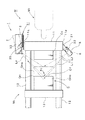
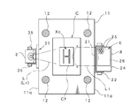
図2(図3)は、金型監視システム1を取付けた射出成形機Mの一部を示す。射出成形機Mは型締装置Mcを備え、この型締装置Mcは、固定盤11,この固定盤11と不図示の圧受盤間に架設した四本のタイバー12…,これらのタイバー12…にスライド自在に装填した可動盤13を備える。そして、固定盤11には固定型Ccが、また、可動盤13には可動型Cmがそれぞれ取付けられ、この固定型Ccと可動型Cmにより金型Cを構成する。これにより、可動盤13は固定盤11に対し、不図示の駆動機構により進退移動し、金型Cの型閉,型締,型開を行うことができる。なお、Miは射出装置,Cf(図3)は金型Cのキャビティをそれぞれ示す。
FIG. 2 (FIG. 3) shows a part of the injection molding machine M to which the
一方、金型監視システム1は、キャビティ部位Xcに対して可視光線以外の光線Lとなる赤外線Liを投射する発光部8と、可視光線を遮断するフィルタ部9(図4)を通してキャビティ部位Xcから反射する赤外線Li(正反射光Lr)をイメージセンサ3により撮像する監視カメラ部2を備える。
On the other hand, the
発光部8は、図2及び図3に示すように、固定盤11の一方の側面11pに複数のボルト等により固定されたブラケット21により支持される。なお、発光部8の取付位置(取付高さ)は、図3に示すように、キャビティ部位Xcの位置(高さ)に一致させる。また、発光部8の投射角度は、取付ねじ22,22により任意に設定(変更)できる。さらに、発光部8は、偏平直方体形に形成し、一面を開放したハウジング部24を備える。ハウジング部24の内部には、赤外線(光線L)を発光する多数の赤外線発光ダイオード25…を配列させた発光基板26を配設する。この発光基板26は、点発光となる各赤外線発光ダイオード25…を集積させた面発光体Eを構成する。この面発光体Eの大きさ(形状)は、キャビティ部位Xcに対する監視範囲に対応して設定し、特に、監視範囲に対して同一又はこれ以上の面積となるように考慮する。赤外線発光ダイオード25…は、千鳥状に配列させることが望ましい。発光部8をこのように構成することにより、照度が高められることに加え、照度の均一性が高められる。なお、ハウジング部24の内部には、発光に対する拡散板を配設し、金型Cにおける研磨パターンによる反射光の減衰を抑えるとともに、均一かつ安定した照射ができるように考慮する。
2 and 3, the
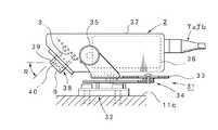
他方、監視カメラ部2は、図2及び図3に示すように、固定盤11の他方の側面11qに取付けた支持機構31により支持される。支持機構31は、複数のボルト等により側面11q上に固定した取付部32と、監視カメラ部2を支持するブラケット33と、このブラケット33と取付部32間に介在する位置調整部34を備える。なお、監視カメラ部2の取付位置(取付高さ)は、図3に示すように、キャビティ部位Xcの位置(高さ)に一致させる。これにより、ブラケット33は、位置調整部34により取付部32に対して前後方向に位置調整でき、監視カメラ部2の前後方向の位置を調整できる。また、監視カメラ部2の撮像角度は、取付ねじ35,35により任意に設定(変更)できる。
On the other hand, the
さらに、監視カメラ部2は、直方体形に形成したケーシング部37を備え、内部には付属回路36(処理部4)を収容するとともに、前部にはイメージセンサ3を有するセンシング部38を所定の角度Rを付けた取付ける。この角度Rを付けることにより、監視カメラ部2を取付けることに伴う横側方への突出を少なくできる。また、センシング部38は、光学筒39を備え、この光学筒39には、前側から、可視光線を遮断するフィルタ部9,レンズ40を順次内蔵するとともに、この光学筒39の後方に、イメージセンサ3を内蔵する。イメージセンサ3としては、省電力化,小型化及び低コスト化の容易なCMOSイメージセンサを用いることが望ましい。
Furthermore, the
このように、発光部8を、型締装置Mcにおける固定盤11の一方の側面11pに取付けるとともに、監視カメラ部2を、固定盤11の他方の側面11qに取付ければ、監視カメラ部2は、発光部8から発光される赤外線Liの正反射光Lr、即ち、軸線に対して発光部8から入射する入射角とこれに基づく反射角が同じ大きさとなる反射光を容易に得ることができる。
In this way, if the
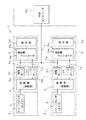
次に、本発明の要部となるシステム構成について、図1を参照して説明する。2は監視カメラ部であり、前述したイメージセンサ3とこのイメージセンサ3に接続した処理部(制御部)4を内蔵する。この処理部4は、マイコン(マイクロコンピュータ)等を利用し、イメージセンサ3から得る画像データ(画像信号)Dvに対して画像処理を行うことにより、キャビティ部位Xcの状態(正常状態又は異常状態)を判別する機能を備えるとともに、各種の制御機能及び処理機能を備えており、上述した付属回路36としてケーシング部37に内蔵する。
Next, a system configuration that is a main part of the present invention will be described with reference to FIG.
また、この処理部4は、接続ポートとして、少なくとも入出力ポート(I/Oポート)2oと通信ポート2tを備える。この場合、入出力ポート2oは、射出成形機Mに内蔵する成形機コントローラ5の入出力ポートに、第一接続ラインTaにより接続する。これにより、少なくとも処理部4から得るキャビティ部位Xcの状態を判別した結果となる異常データ(エラー信号)Deが、第一接続ラインTaを介して成形機コントローラ5に付与される。一方、通信ポート2tは第二接続ラインTbに接続する。この第二接続ラインTbには、イーサネット(登録商標)等のLAN7を用いることができる。したがって、この第二接続ラインTb(LAN7)に成形機コントローラ5の通信ポートを接続すれば、成形機コントローラ5と処理部4は、LAN7を介した通信が可能になる。これにより、イメージセンサ3から得る画像データ(画像信号)Dvが、第二接続ラインTb(LAN7)を介して成形機コントローラ5に送信される。
The processing unit 4 includes at least an input / output port (I / O port) 2o and a
このように、第二接続ラインTbに、LAN7を用いれば、図1に示すように、他の一又は二以上の射出成形機M…に取付けられる監視カメラ部2…の通信ポート2t…及び成形機コントローラ5…の通信ポートも、同一のLAN7に接続できるとともに、他の場所(管理室等)に設置された中央コンピュータPC等も、同一のLAN7に接続することができる。したがって、このようなLAN7を構築することにより、他の射出成形機M…とのデータ授受や他の場所に設置された中央コンピュータPC等とのデータ授受を容易かつ迅速に行うことができる。なお、図1は、LAN7を用いた接続形態の一例であり、基本的には、一台の射出成形機Mにおける監視カメラ部2の通信ポート2tと成形機コントローラ5の通信ポートをLAN7により接続すればよい。
As described above, when the
他方、成形機コントローラ5には、この成形機コントローラ5に付属する表示部5dを備える。この表示部5dは、タッチパネルを付設したカラー液晶ディスプレイ等を用いることができる。したがって、この表示部5dは、成形機本体に係わる各種データの表示や設定等に用いられる。また、成形機コントローラ5には、第二接続ラインTbを介して送信される画像データ(画像信号)Dvに係わる画像を表示部5dに表示するための画像表示機能Fdを備える。これにより、画像データDvに係わる画像、即ち、キャビティ部位Xcの画像を表示部5dに表示することができ、この表示部5dは、監視カメラ部2側(イメージセンサ3)から送信される画像データDvに係わる画像を表示するための表示部を兼用する。よって、監視カメラ部2側の表示部は不要になるため、システム全体のコストダウン及び設置性向上に寄与できる。
On the other hand, the
さらに、成形機コントローラ5には、異常データDeに対応する画像データDvを、ショット番号に対応させてメモリに登録するデータ記憶機能Fmを備える。即ち、成形機コントローラ5には、監視カメラ部2から、異常データDe及び画像データDvが同時に付与されているため、異常データDeに対応する画像データDvを、ショット番号に対応させて成形機コントローラ5に内蔵するメモリに登録することができる。なお、このようなデータ記憶機能Fmは、監視カメラ部2側にも同様に設けることができる。
Further, the
次に、本実施形態に係る金型監視システム1の使用方法及び動作について、図1〜図7を参照して説明する。
Next, the usage method and operation | movement of the metal mold | die
最初に、発光部8と監視カメラ部2の角度設定を行う。今、型開した可動型Cmの位置が図2に示す実線位置にあるものとする。この状態で発光部8から投射される赤外線Liの角度(投射角度)が、キャビティ部位Xcの全体に当たるように設定する。この場合、投射角度は、取付ねじ22…の弛緩又は締付により容易に設定できる。これにより、赤外線Liは、キャビティ部位Xcに対して斜めに投射される。
First, the angle setting of the
次いで、監視カメラ部2の撮像角度を設定する。この場合、図2に示すように、キャビティ部位Xcから反射する赤外線Liの正反射光Lrを撮像できるように設定する。このような正反射光Lrを撮像することにより、反射率の差により検出できるため、S/N比を高くできるとともに、他の角度からの光の影響を低減できる。なお、撮像角度は、取付ねじ35…の弛緩又は締付により容易に設定できる。また、型開した際における可動型Cmの位置が、図2に仮想線で示すCma,Cmbのように変更された場合であっても、同様の操作により容易に設定することができる。
Next, the imaging angle of the
さらに、基準画像データの設定を行う。この場合、正常(良品)な成形品が付着したキャビティCfの状態を撮像し、一次基準画像データとして登録するとともに、成形品が付着していないキャビティCfのみの状態を撮像し、二次基準画像データとして登録する。登録に際しては、まず、赤外線発光ダイオード25…を点灯させる。これにより、赤外線Liはキャビティ部位Xcに対して投射され、キャビティ部位Xcで正反射する。反射した赤外線Li(正反射光Lr)は、監視カメラ部2のセンシング部38に入光し、イメージセンサ3に結像する。この際、射出成形機M周辺の可視光線はフィルタ部9によりカットされ、反射した赤外線Li(正反射光Lr)のみがイメージセンサ3に結像する。そして、イメージセンサ3から得られる画像データ(画像信号)Dvは、処理部4に付与されることにより内蔵するメモリ(画像メモリ)に書き込まれる。
Further, reference image data is set. In this case, the state of the cavity Cf to which a normal (non-defective) molded product is attached is imaged and registered as primary reference image data, and the state of only the cavity Cf to which no molded product is attached is imaged to obtain a secondary reference image. Register as data. In registration, first, the infrared
次に、実際の成形工程における監視方法について説明する。なお、射出成形機Mの稼働中においては、成形機コントローラ5から処理部4に対して各種信号が付与されるとともに、処理部4から成形機コントローラ5に対して各種信号が付与される。この場合、処理部4(成形機コントローラ5)は、複数の入出力ポート2o…を備えており、一部の入出力ポート2o…がこれらの信号の授受に利用される。今、射出充填工程及び冷却工程を経て、金型Cの型開きが終了したものとする。処理部4には、型開きが終了したことに伴う型開終了信号が付与されるため、処理部4による一次監視処理が行われる。この一次監視処理は、型開き後、エジェクタ動作前に行う監視処理であり、これにより、成形品に未充填部分が存在するか否かなどの成形不良の判別を行うことができる。
Next, a monitoring method in an actual molding process will be described. During the operation of the injection molding machine M, various signals are given from the
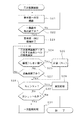
図5には、この一次監視処理の処理手順をフローチャートで示す。また、図7には、データの流れをフローチャートで示す。まず、処理部4に型開終了信号が付与されれば、処理部4は、撮像開始指令を出力し、発光部8における赤外線発光ダイオード25…を点灯させるとともに、監視カメラ部2を作動させて撮像を開始する(ステップS1)。これにより、発光部8からキャビティ部位Xcに対して赤外線Liが投射され、キャビティ部位Xcで正反射する。反射した赤外線Li(正反射光Lr)は、監視カメラ部2のセンシング部38に入光し、イメージセンサ3に結像する。この際、射出成形機M周辺の可視光線はフィルタ部9によりカットされ、反射した赤外線Li(正反射光Lr)のみがイメージセンサ3に投射される。そして、イメージセンサ3から得られる画像データ(画像信号)Dvは、処理部4に付与される。なお、赤外線Liを用いるため、点灯時であっても可視光線とは異なり、オペレータに違和感や不快感を与えることはない。
FIG. 5 is a flowchart showing the processing procedure of the primary monitoring process. FIG. 7 is a flowchart showing the data flow. First, when a mold opening end signal is given to the processing unit 4, the processing unit 4 outputs an imaging start command, turns on the infrared
また、一画面分の画像データDvが処理部4に取り込まれたなら、処理部4は、撮像終了指令を出力する。これにより、発光部8における赤外線発光ダイオード25…を消灯させ、かつイメージセンサ3による撮像を終了させる(ステップS2,S3)。このように、発光部8は、撮像するときのみ点灯させるため、消費電力の低減を図ることができる。さらに、画像データDvは、通信ポート2tからLAN7(第二接続ラインTb)を介して成形機コントローラ5の通信ポートに送信される(ステップS41,S42)。そして、成形機コントローラ5に付属する表示部5d上に、キャビティCfのカラー画像として表示される(ステップS43)。
Further, when the image data Dv for one screen is taken into the processing unit 4, the processing unit 4 outputs an imaging end command. As a result, the infrared
一方、処理部4では、撮像した最初の画素(ピクセル)における画素レベルと前述した一次基準画像データにおける対応する画素レベルを比較して両者の偏差を演算する画像処理を行う(ステップS4)。そして、求めた偏差としきい値を比較する(ステップS5)。この際、正常に成形が行われていれば、[偏差≦しきい値]となるが、一部に充填不良等が存在すると、その部分は、[偏差>しきい値]となるため、特異点として計数(カウント)される(ステップS6)。以下、順次続く画素に対して同様の処理を繰り返し、最終の画素まで行う(ステップS7,S4…)。 On the other hand, the processing unit 4 compares the pixel level of the first imaged pixel (pixel) with the corresponding pixel level in the primary reference image data described above, and performs image processing to calculate the deviation between them (step S4). Then, the obtained deviation is compared with the threshold value (step S5). At this time, if molding is performed normally, [deviation ≦ threshold] is obtained. However, if there is a filling defect in a part, the part becomes [deviation> threshold]. The points are counted (counted) (step S6). Thereafter, the same processing is repeated for the successive pixels until the last pixel (steps S7, S4...).
さらに、処理部4は、得られた特異点の計数値(合計値)Ncと予め異常を判別するために設定した異常レベルNeを比較し、[Nc>Ne]の場合には、異常が発生したものと判断して所定の異常処理を行う(ステップS8,S9)。即ち、異常データDeを入出力ポート2oから出力し、第一接続ラインTaを介して成形機コントローラ5の入出力ポートに付与する(ステップS44,S45,S46)。これにより、射出成形機Mの動作を停止するとともに、異常表示等の異常処理を行う。また、成形機コントローラ5は、データ記憶機能Fmにより、少なくとも異常データDeに対応する画像データDvを、ショット番号に対応させてメモリに登録する(ステップS47,S48,S49)。これにより、一次監視処理における異常発生時の画像データDvを容易かつ確実に保存でき、分析及び統計等のデータ処理を的確かつ迅速に行うことができる。
Further, the processing unit 4 compares the obtained singular point count value (total value) Nc with the abnormality level Ne set in advance to determine abnormality, and if [Nc> Ne], abnormality occurs. It is determined that a failure has occurred, and predetermined abnormality processing is performed (steps S8 and S9). That is, the abnormal data De is output from the input / output port 2o and is given to the input / output port of the
他方、異常が発生していない場合には、計数値Ncと予め設定したアラームレベルNaを比較し、[Nc>Na]の場合には、異常直前の状態である旨の処理、即ち、射出成形機Mの動作を停止するとともに、予備警報としてのアラーム表示等のアラーム処理を行う(ステップS10,S11)。これに対して、一次監視処理の結果、正常の場合には、二次監視処理に移行させる(ステップS12)。なお、このような監視処理においては、偏差に対するしきい値による判別と、特異点の計数値に対する基準レベルによる判別の両方を行うため、判別精度が高められる。 On the other hand, if no abnormality has occurred, the count value Nc is compared with a preset alarm level Na. If [Nc> Na], the processing to the effect immediately before the abnormality, that is, injection molding. The operation of the machine M is stopped and alarm processing such as alarm display as a preliminary warning is performed (steps S10 and S11). On the other hand, if the result of the primary monitoring process is normal, the process proceeds to the secondary monitoring process (step S12). In such a monitoring process, both discrimination by a threshold for deviation and discrimination by a reference level for a count value of a singular point are performed, so that discrimination accuracy is improved.
図6に、二次監視処理の処理手順をフローチャートで示す。この二次監視処理は、エジェクタ動作後に行う監視処理であり、これにより、エジェクタが正常に行われたか否かを判別することができる。今、成形機コントローラ5からエジェクタ終了信号が処理部4に付与されれば、処理部4は、撮像開始指令を出力し、発光部8における赤外線発光ダイオード25…を点灯させるとともに、監視カメラ部2を作動させて撮像を開始する(ステップS21)。これにより、発光部8からキャビティ部位Xcに対して赤外線Liが投射され、キャビティ部位Xcで正反射する。また、反射した赤外線Li(正反射光Lr)は、監視カメラ部2のセンシング部38入光し、イメージセンサ3に結像する。この際、射出成形機M周辺の可視光線はフィルタ部9によりカットされ、反射した赤外線Li(正反射光Lr)のみがイメージセンサ3に結像する。そして、イメージセンサ3から得られる画像データDvは処理部4に付与される。
FIG. 6 is a flowchart showing the processing procedure of the secondary monitoring process. This secondary monitoring process is a monitoring process performed after the ejector operation, whereby it is possible to determine whether or not the ejector has been normally performed. Now, if an ejector end signal is given from the
また、一画面分の画像データDvが処理部4に取り込まれたなら、処理部4は、撮像終了指令を出力する。これにより、発光部8における赤外線発光ダイオード25…を消灯させ、かつイメージセンサ3による撮像を終了させる(ステップS22,S23)。さらに、画像データDvは、通信ポート2tからLAN7(第二接続ラインTb)を介して成形機コントローラ5の通信ポートに送信される(ステップS41,S42)。そして、成形機コントローラ5に付属する表示部5d上に、キャビティCfのカラー画像として表示される(ステップS43)。
Further, when the image data Dv for one screen is taken into the processing unit 4, the processing unit 4 outputs an imaging end command. As a result, the infrared
一方、処理部4では、最初の画素における画素レベルと前述した二次基準画像データにおける対応する画素レベルを比較して両者の偏差を演算する画像処理を行う(ステップS24)。また、求めた偏差としきい値を比較する(ステップS25)。この際、成形品が正常に排出されていれば、[偏差≦しきい値]となるが、正常に排出されていない場合は、成形品の存在する部分が、[偏差>しきい値]となるため、特異点として計数(カウント)される(ステップS26)。以下、順次続く画素に対して同様の処理を繰り返し、最終の画素まで行う(ステップS27,S24…)。 On the other hand, the processing unit 4 compares the pixel level in the first pixel with the corresponding pixel level in the secondary reference image data described above, and performs image processing for calculating the deviation between them (step S24). Further, the obtained deviation is compared with the threshold value (step S25). At this time, if the molded product is normally discharged, [deviation ≦ threshold] is obtained. If the molded product is not normally discharged, the portion where the molded product exists is [deviation> threshold]. Therefore, it is counted (counted) as a singular point (step S26). Thereafter, the same processing is repeated for successive pixels until the last pixel (steps S27, S24...).
さらに、処理部4は、得られた特異点の計数値(合計値)Ncと予め異常を判別するために設定した異常レベルNxを比較し、[Nc>Nx]の場合には、異常が発生したものとして所定の異常処理を行う(ステップS28,S29)。即ち、異常データDeを入出力ポート2oから出力し、第一接続ラインTaを介して成形機コントローラ5の入出力ポートに付与する(ステップS44,S45,S46)。これにより、射出成形機Mの動作を停止するとともに、異常表示等の異常処理を行う。また、成形機コントローラ5は、データ記憶機能Fmにより、少なくとも異常データDeに対応する画像データDvを、ショット番号に対応させてメモリに登録する(ステップS47,S48,S49)。これにより、二次監視処理における異常発生時の画像データDvを容易かつ確実に保存でき、分析及び統計等のデータ処理を的確かつ迅速に行うことができる。一方、正常であって、次のショットが行われる場合には、図5に示す一次監視処理に移行させる(ステップS30,S31)。また、次のショットが無い場合には終了する(ステップS30)。
Further, the processing unit 4 compares the obtained singular point count value (total value) Nc with the abnormality level Nx set in advance to determine abnormality, and if [Nc> Nx], abnormality occurs. As a result, predetermined abnormality processing is performed (steps S28 and S29). That is, the abnormal data De is output from the input / output port 2o and is given to the input / output port of the
このような本実施形態に係る金型監視システム1によれば、画像処理を監視カメラ部2側で行い、この画像処理に基づく少なくとも異常データDe及び画像データDvを成形機コントローラ5に送信するようにしたため、監視カメラ部2を取付けた場合であっても成形機コントローラ5における処理の負担はほとんど変わらない。したがって、成形機コントローラ5による成形機本体に対する本来の制御に遅れ等の支障を生じる不具合を確実に回避できる。しかも、異常データDeは、画像データDvを送信する第二接続ラインTbとは異なる第一接続ラインTaを介して送るため、成形機Mにとって最重要データとなる異常データDeの処理に対する遅れ等の不具合も確実に回避できる。また、監視カメラ部2を高性能カメラ等に変更し、この変更に伴ってソフトウェアやデバイスを変更したり或いは成形サイクルの高速化に対応して画像処理の手法を変更する場合であっても、成形機コントローラ5側のソフトウェアやデバイスの変更は不要になるため、容易かつ柔軟に対応でき、汎用性及び発展性を高めることができるとともに、コストダウンにも寄与できる。なお、キャビティ部位Xcに対して可視光線以外の光線Lを投射する発光部8を設け、また、監視カメラ部2に、キャビティ部位Xcの反射光Lrから可視光線を除いてイメージセンサ3に付与するフィルタ部9を設ければ、射出成形機M周辺の明るさや成形品の色の影響を原理的に排除でき、誤動作を確実に防止して信頼性及び安全性を高めることができるとともに、画像処理の簡易化及び高精度化を図ることができる。
According to such a
以上、最良の実施形態について詳細に説明したが、本発明は、このような実施形態に限定されるものではなく、細部の構成,形状,素材,数量,数値等において、本発明の要旨を逸脱しない範囲で、任意に変更,追加,削除することができる。 Although the best embodiment has been described in detail above, the present invention is not limited to such an embodiment, and departs from the gist of the present invention in the detailed configuration, shape, material, quantity, numerical value, and the like. It can be changed, added, or deleted as long as it is not.
例えば、例示の実施形態では、可視光線以外の光線Lとして、赤外線Liを利用したが、必ずしも赤外線Liに限定されるものではなく、紫外線,遠赤外線等の他の光線を用いることもできる。また、発光部8には、多数の発光ダイオード25…を用いた場合を例示したが、他の発光手段であってもよい。さらに、入出力ポート2oから少なくとも異常データDeが出力する場合を示したが、出力するデータには、正常データ等の他の同類のデータを含めてもよい。なお、入出力ポート2oは、「0」,「1」信号となる異常データDeを出力可能なポートを意味し、通信ポート2tは、イメージデータを送信可能なポートを意味するものであり、その名称に制約されるものではない。一方、第二接続ラインTbには、各種LAN(無線LAN等を含む)を利用できるとともに、LAN以外の通信ラインであってもよい。また、実施形態では、一次監視処理と二次監視処理の双方を実施する場合を例示したが、いずれか一方の監視処理の実施であってもよい。他方、金型監視システム1を取付ける対象として射出成形機Mを例示したが、金型Cを用いる各種成形機に適用することができる。
For example, in the illustrated embodiment, the infrared rays Li are used as the light rays L other than the visible light rays, but are not necessarily limited to the infrared rays Li, and other light rays such as ultraviolet rays and far infrared rays may be used. Moreover, although the case where many light emitting
1 金型監視システム
2 監視カメラ部
2o 入出力ポート
2t 通信ポート
3 イメージセンサ
4 処理部
5 成形機コントローラ
5d 表示部
7 LAN
8 発光部
9 フィルタ部
C 金型
Dv 画像データ
De 異常データ
Xc キャビティ部位
M 成形機
Ta 第一接続ライン
Tb 第二接続ライン
Fd 画像表示機能
Fm データ記憶機能
L 可視光線以外の光線
Lr 反射光
DESCRIPTION OF
8
Claims (5)
Priority Applications (1)
| Application Number | Priority Date | Filing Date | Title |
|---|---|---|---|
| JP2004112475A JP4138694B2 (en) | 2004-04-06 | 2004-04-06 | Mold monitoring system for molding machine |
Applications Claiming Priority (1)
| Application Number | Priority Date | Filing Date | Title |
|---|---|---|---|
| JP2004112475A JP4138694B2 (en) | 2004-04-06 | 2004-04-06 | Mold monitoring system for molding machine |
Publications (3)
| Publication Number | Publication Date |
|---|---|
| JP2005297218A true JP2005297218A (en) | 2005-10-27 |
| JP2005297218A5 JP2005297218A5 (en) | 2005-12-08 |
| JP4138694B2 JP4138694B2 (en) | 2008-08-27 |
Family
ID=35329366
Family Applications (1)
| Application Number | Title | Priority Date | Filing Date |
|---|---|---|---|
| JP2004112475A Expired - Fee Related JP4138694B2 (en) | 2004-04-06 | 2004-04-06 | Mold monitoring system for molding machine |
Country Status (1)
| Country | Link |
|---|---|
| JP (1) | JP4138694B2 (en) |
Cited By (2)
| Publication number | Priority date | Publication date | Assignee | Title |
|---|---|---|---|---|
| JP2015179348A (en) * | 2014-03-19 | 2015-10-08 | 株式会社Kmc | Mold electronic medical chart system and mold |
| CN114506043A (en) * | 2020-11-17 | 2022-05-17 | 精工爱普生株式会社 | Molding machine management system and recording medium |
Families Citing this family (1)
| Publication number | Priority date | Publication date | Assignee | Title |
|---|---|---|---|---|
| JP6716185B1 (en) * | 2019-09-05 | 2020-07-01 | 株式会社ソディック | Image recording device for injection molding machine |
-
2004
- 2004-04-06 JP JP2004112475A patent/JP4138694B2/en not_active Expired - Fee Related
Cited By (4)
| Publication number | Priority date | Publication date | Assignee | Title |
|---|---|---|---|---|
| JP2015179348A (en) * | 2014-03-19 | 2015-10-08 | 株式会社Kmc | Mold electronic medical chart system and mold |
| CN114506043A (en) * | 2020-11-17 | 2022-05-17 | 精工爱普生株式会社 | Molding machine management system and recording medium |
| CN114506043B (en) * | 2020-11-17 | 2023-12-15 | 精工爱普生株式会社 | Molding machine management system and recording media |
| US12076899B2 (en) | 2020-11-17 | 2024-09-03 | Seiko Epson Corporation | Molding machine management system and computer program |
Also Published As
| Publication number | Publication date |
|---|---|
| JP4138694B2 (en) | 2008-08-27 |
Similar Documents
| Publication | Publication Date | Title |
|---|---|---|
| US7175408B2 (en) | Mold monitoring apparatus for injection molding machine | |
| CN104848996A (en) | Motorcycle wheel hub air-tightness detection method and device | |
| CN103031670B (en) | Sewing machine | |
| US9782921B2 (en) | Injection molding system with additional injection device | |
| CN113407475A (en) | Control module and method | |
| JP4138694B2 (en) | Mold monitoring system for molding machine | |
| CN116208805A (en) | Failsafe surround view | |
| JP3728423B2 (en) | Mold monitoring device for injection molding machine | |
| IT201800010372A1 (en) | HEADLIGHT TEST SYSTEM FOR A VEHICLE. | |
| KR102118250B1 (en) | Mold temperature control system of injection molding machine | |
| JP2000180696A (en) | Television lens system | |
| JP4112544B2 (en) | Molding monitoring system | |
| JP4112537B2 (en) | Molding monitoring system and molding monitoring method | |
| JP4081038B2 (en) | Mold monitoring method for molding machine | |
| KR102115656B1 (en) | Temperature control system of injection molding machine | |
| JP4152367B2 (en) | Molding monitoring system | |
| JP2002166457A (en) | Injection molding machine | |
| US12148217B2 (en) | Monitoring device, and monitoring method | |
| JP5825293B2 (en) | Operation confirmation method for abnormal situation automatic detection device | |
| KR100485306B1 (en) | Supervisory apparatus of plastic injection molding machine | |
| KR100267864B1 (en) | Alarm process apparatus and control method of asymmetric digital subscriber line system | |
| JP2005125709A (en) | Mold monitoring apparatus, mold monitoring method and program | |
| JP4252417B2 (en) | Monitoring device and monitoring method for molding machine | |
| KR100485304B1 (en) | Supervisory method of plastic injection molding machine | |
| JP4061737B2 (en) | Pan head device |
Legal Events
| Date | Code | Title | Description |
|---|---|---|---|
| A521 | Written amendment |
Free format text: JAPANESE INTERMEDIATE CODE: A523 Effective date: 20051014 |
|
| A621 | Written request for application examination |
Free format text: JAPANESE INTERMEDIATE CODE: A621 Effective date: 20051014 |
|
| A977 | Report on retrieval |
Free format text: JAPANESE INTERMEDIATE CODE: A971007 Effective date: 20070720 |
|
| A131 | Notification of reasons for refusal |
Free format text: JAPANESE INTERMEDIATE CODE: A131 Effective date: 20070801 |
|
| A521 | Written amendment |
Free format text: JAPANESE INTERMEDIATE CODE: A523 Effective date: 20071001 |
|
| A02 | Decision of refusal |
Free format text: JAPANESE INTERMEDIATE CODE: A02 Effective date: 20080109 |
|
| A521 | Written amendment |
Free format text: JAPANESE INTERMEDIATE CODE: A523 Effective date: 20080207 |
|
| A521 | Written amendment |
Free format text: JAPANESE INTERMEDIATE CODE: A523 Effective date: 20080415 |
|
| A911 | Transfer of reconsideration by examiner before appeal (zenchi) |
Free format text: JAPANESE INTERMEDIATE CODE: A911 Effective date: 20080418 |
|
| TRDD | Decision of grant or rejection written | ||
| A01 | Written decision to grant a patent or to grant a registration (utility model) |
Free format text: JAPANESE INTERMEDIATE CODE: A01 Effective date: 20080514 |
|
| A01 | Written decision to grant a patent or to grant a registration (utility model) |
Free format text: JAPANESE INTERMEDIATE CODE: A01 |
|
| A61 | First payment of annual fees (during grant procedure) |
Free format text: JAPANESE INTERMEDIATE CODE: A61 Effective date: 20080605 |
|
| R150 | Certificate of patent (=grant) or registration of utility model |
Free format text: JAPANESE INTERMEDIATE CODE: R150 |
|
| FPAY | Renewal fee payment (prs date is renewal date of database) |
Free format text: PAYMENT UNTIL: 20110613 Year of fee payment: 3 |
|
| FPAY | Renewal fee payment (prs date is renewal date of database) |
Free format text: PAYMENT UNTIL: 20110613 Year of fee payment: 3 |
|
| FPAY | Renewal fee payment (prs date is renewal date of database) |
Free format text: PAYMENT UNTIL: 20140613 Year of fee payment: 6 |
|
| LAPS | Cancellation because of no payment of annual fees |