JP2005297130A - Cross hole deburring tool - Google Patents
Cross hole deburring tool Download PDFInfo
- Publication number
- JP2005297130A JP2005297130A JP2004116980A JP2004116980A JP2005297130A JP 2005297130 A JP2005297130 A JP 2005297130A JP 2004116980 A JP2004116980 A JP 2004116980A JP 2004116980 A JP2004116980 A JP 2004116980A JP 2005297130 A JP2005297130 A JP 2005297130A
- Authority
- JP
- Japan
- Prior art keywords
- cutting blade
- deburring tool
- cutting
- hole
- cross
- Prior art date
- Legal status (The legal status is an assumption and is not a legal conclusion. Google has not performed a legal analysis and makes no representation as to the accuracy of the status listed.)
- Withdrawn
Links
Images

Landscapes
- Milling Processes (AREA)
Abstract
【課題】加工品内部の交差孔の交差部分に生じるバリを効率よく切除できるバリ取り工具を提供する。
【解決手段】回転軸部1の回転中心の周囲に放射状に配設した複数の切刃部2を設ける。切刃部の外縁部には所定のすくい角を有する切削刃3を形成する。前記バリ取り工具を孔内に挿入し、複数の孔の交差部分にて回転軸部を中心として回転させることにより、切刃部の外縁部に形成した切削刃によりバリを能率よく切除することができる。
【選択図】図1There is provided a deburring tool capable of efficiently cutting a burr generated at a crossing portion of a cross hole in a workpiece.
A plurality of cutting blade portions 2 are provided radially around a rotation center of a rotary shaft portion 1. A cutting blade 3 having a predetermined rake angle is formed on the outer edge portion of the cutting blade portion. By inserting the deburring tool into the hole and rotating the rotating shaft around the rotating shaft at the intersection of the plurality of holes, the cutting blade formed on the outer edge of the cutting edge can efficiently cut off the burr. it can.
[Selection] Figure 1
Description
本発明は交差孔のバリ取り工具に関し、より詳しくは加工品の内部にて交差する複数の孔の交差部分に発生するバリを切除するための工具に関する。 The present invention relates to a deburring tool for cross holes, and more particularly to a tool for cutting off burrs generated at intersecting portions of a plurality of holes intersecting inside a workpiece.
ドリル等の切削工具により加工した孔の開口部に生じるバリを除去するための工具としては例えば特許文献1に示したものが知られている。
従来のバリ取り工具は加工品の外部に露出した孔の開口部周縁に生じるバリを除去する目的で作られており、加工品の孔内に生じるバリについては除去不能であった。孔内のバリは、加工品に互いに交差するように複数の孔を加工した場合に、各孔内壁の交差部分に形成される稜線部分に発生する。このような交差孔内に生じるバリは従来は孔径よりも細いヤスリ等を用いて手作業で除去していたため能率が悪かった。 Conventional deburring tools are made for the purpose of removing burrs generated at the periphery of the opening of the hole exposed to the outside of the workpiece, and burrs generated in the hole of the workpiece cannot be removed. The burrs in the holes are generated at ridge portions formed at the intersecting portions of the inner walls of the holes when a plurality of holes are machined so as to intersect with each other. Conventionally, the burrs generated in such cross holes have been removed manually by using a file or the like that is thinner than the hole diameter, so that the efficiency is poor.
本発明はこのような問題点に着目してなされたもので、加工品内部の交差孔の交差部分に生じるバリを効率よく切除できるバリ取り工具を提供することを目的としている。 The present invention has been made paying attention to such problems, and an object of the present invention is to provide a deburring tool capable of efficiently removing burrs generated at the intersections of cross holes in a workpiece.
本発明は、回転軸部と、該回転軸部の回転中心の周囲に放射状に配設した複数の切刃部からなる。前記切刃部は、前記回転中心と直交する方向から見た最大投影形状が加工の対象となる孔の半径以下の半円形状となるように形成する。また、該切刃部の外縁部には所定のすくい角を有する切削刃を形成する。 The present invention includes a rotating shaft portion and a plurality of cutting blade portions arranged radially around the rotation center of the rotating shaft portion. The cutting edge portion is formed so that a maximum projected shape viewed from a direction orthogonal to the rotation center has a semicircular shape equal to or less than a radius of a hole to be processed. A cutting blade having a predetermined rake angle is formed on the outer edge of the cutting blade portion.
本発明に係るバリ取り工具を孔内に挿入し、複数の孔の交差部分にて回転軸部を中心として回転させることにより、切刃部の外縁部に形成した切削刃によりバリを切除することができる。作業は工具を加工品の孔内に挿入して手動または電動機等により回転させるだけであるので能率よくバリ取りを行うことができる。 The deburring tool according to the present invention is inserted into the hole, and the burr is cut off by the cutting blade formed on the outer edge portion of the cutting blade portion by rotating around the rotating shaft portion at the intersection of the plurality of holes. Can do. Deburring can be performed efficiently because the work is simply performed by inserting the tool into the hole of the workpiece and rotating it manually or by an electric motor.
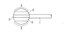
以下、本発明の実施形態を図面に基づいて説明する。図1または図2において、1は回転軸部、2は板状の切刃部を示している。切刃部2は複数のもの(この場合、4個)を回転軸部1の一端部に、その回転中心の周囲に等角度間隔で放射状に配設してある。 Hereinafter, embodiments of the present invention will be described with reference to the drawings. In FIG. 1 or FIG. 2, 1 is a rotating shaft part, 2 is a plate-shaped cutting blade part. A plurality of cutting blade portions 2 (in this case, four pieces) are arranged radially at equal angular intervals around one end of the rotating shaft portion 1 and around the center of rotation.
前記切刃部2は、前記回転中心と直交する方向から見た最大投影形状が加工の対象となる孔の半径以下の外径を有する半円形状となるように形成してある。切刃部2の外形形状は、孔内に生じるバリに確実に当接する限り必ずしも真円形状でなくともよい。
The
前記切刃部2の外縁部には所定のすくい角gを有する切削刃3を形成してある。この実施形態では、切削刃3を回転方向によらず作業できるように各切刃部2の両面に設けてある。また、切削刃3は前記切刃部外縁部に沿って連続した円弧形状に設けてあるが、該外縁部の全体ではなく、バリを切除するのに必要な程度に部分的に設けてある。
A
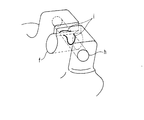
図3は前記バリ取り工具を適用したバリ取り作業の様子を示している。加工物内にて交差するように2方向からドリル等により孔aとbを形成すると、その交差部分の内壁面に生じる稜部c〜dにバリが発生する。このように交差孔内にバリを生じる加工品の一例として、図4に示したようなナックルハウジングがある。図のfはボールジョイントが挿入される孔部、hは前記孔部fに挿入されたボールジョイントを締結するためのボルトを挿入する孔部である。各孔部f、hが交差する稜部iにバリが発生する。 FIG. 3 shows a deburring operation using the deburring tool. When holes a and b are formed from two directions by a drill or the like so as to intersect within the workpiece, burrs are generated at ridges c to d generated on the inner wall surface of the intersecting portion. As an example of a processed product that generates burrs in the cross hole, there is a knuckle housing as shown in FIG. In the figure, f is a hole into which the ball joint is inserted, and h is a hole into which a bolt for fastening the ball joint inserted into the hole f is inserted. A burr | flash generate | occur | produces in the ridge part i where each hole part f and h cross | intersects.
前述のような交差孔内のバリを切除するには、図3に示したように回転軸部1の基端部を電動機等の回転駆動器具(図示せず)に装着し、何れか一方の孔の開口部からバリ取り工具を回転させながら挿入する。このとき工具の切刃部2が孔内壁面に接触しないように図る。工具切刃部2が孔内のバリ部分に位置するように孔開口部からの観察または測定により挿入量を調節しながら切刃部2をバリに当接させて切削を行う。この作業を、必要に応じて他の孔についても実施する。これによりバリを効率よく除去することができる。
In order to remove the burr in the cross hole as described above, the base end portion of the rotary shaft 1 is mounted on a rotary drive device (not shown) such as an electric motor as shown in FIG. Insert the deburring tool while rotating it from the opening of the hole. At this time, the
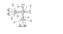
図5に切刃部2に関する他の実施形態を示す。この実施形態は、切削刃3を形成する切刃部2の外縁部を多数の凹凸からなる歯型形状に形成してある。このように切刃部2を歯型形状とすることにより、バリ取り作業の際の切刃部2とバリとの間で切削抵抗による逃げが起こりにくくなり、切削刃3により確実にバリを捕捉して切削を行うことができる。また、バリと切削刃3とは一度に接触する面積が少なくなるため切削抵抗を軽減すると共に、過大な切削抵抗に原因する工具の破損を防止することができる。切削刃3のすくい角gを適宜に設置することで切削抵抗をより軽減する効果が得られる。
FIG. 5 shows another embodiment relating to the
なお、前記実施形態では4枚の切刃部2を回転軸部1の中心線の周囲に90度の等角度間隔で設けているが、工具を電動機等により高速回転させる場合には、複数の切刃部の角度を若干異ならせて不等角度間隔で設けるようにしてもよく、これにより作業時の共振を防止することができる。
In the above-described embodiment, the four
1 回転軸部
2 切刃部
3 切削刃
g すくい角
1 Rotating
Claims (7)
前記切刃部は、
前記回転中心と直交する方向から見た最大投影形状が加工の対象となる孔の半径以下の半円形状となるように形成すると共に、
該切刃部の外縁部に切削刃を形成したこと
を特徴とする交差孔のバリ取り工具。 A deburring tool for a cross hole comprising a rotating shaft portion and a plurality of cutting blade portions radially disposed around the rotation center of the rotating shaft portion,
The cutting edge portion is
While forming so that the maximum projected shape seen from the direction orthogonal to the rotation center is a semicircular shape less than the radius of the hole to be processed,
A cross-hole deburring tool characterized in that a cutting blade is formed on the outer edge of the cutting blade.
Priority Applications (1)
| Application Number | Priority Date | Filing Date | Title |
|---|---|---|---|
| JP2004116980A JP2005297130A (en) | 2004-04-12 | 2004-04-12 | Cross hole deburring tool |
Applications Claiming Priority (1)
| Application Number | Priority Date | Filing Date | Title |
|---|---|---|---|
| JP2004116980A JP2005297130A (en) | 2004-04-12 | 2004-04-12 | Cross hole deburring tool |
Publications (1)
| Publication Number | Publication Date |
|---|---|
| JP2005297130A true JP2005297130A (en) | 2005-10-27 |
Family
ID=35329295
Family Applications (1)
| Application Number | Title | Priority Date | Filing Date |
|---|---|---|---|
| JP2004116980A Withdrawn JP2005297130A (en) | 2004-04-12 | 2004-04-12 | Cross hole deburring tool |
Country Status (1)
| Country | Link |
|---|---|
| JP (1) | JP2005297130A (en) |
Cited By (2)
| Publication number | Priority date | Publication date | Assignee | Title |
|---|---|---|---|---|
| CN109482979A (en) * | 2018-12-26 | 2019-03-19 | 吉林博仁科技有限责任公司 | A kind of deburrer of oil injector seat phase perforation |
| WO2023135832A1 (en) * | 2022-01-14 | 2023-07-20 | 株式会社ジーベックテクノロジー | Deburring tool and deburring method |
-
2004
- 2004-04-12 JP JP2004116980A patent/JP2005297130A/en not_active Withdrawn
Cited By (3)
| Publication number | Priority date | Publication date | Assignee | Title |
|---|---|---|---|---|
| CN109482979A (en) * | 2018-12-26 | 2019-03-19 | 吉林博仁科技有限责任公司 | A kind of deburrer of oil injector seat phase perforation |
| CN109482979B (en) * | 2018-12-26 | 2024-07-19 | 吉林博仁科技有限责任公司 | Deburring cutter for intersecting holes of oil sprayer seat |
| WO2023135832A1 (en) * | 2022-01-14 | 2023-07-20 | 株式会社ジーベックテクノロジー | Deburring tool and deburring method |
Similar Documents
| Publication | Publication Date | Title |
|---|---|---|
| US8444353B2 (en) | Cutting tool | |
| JPH08243826A (en) | Two-direction spot facing tool | |
| JP2009511286A (en) | Cutting tools | |
| JP6714248B1 (en) | Chamfering cutter and chamfering method for work | |
| US9403222B2 (en) | Method of removing end-surface burr of formed groove and formed rotary cutting tool for chamfering | |
| JP3224520U (en) | End mill | |
| JP2005074523A (en) | Deburring tool | |
| WO2006018894A1 (en) | Chamfering tool | |
| JP2005297130A (en) | Cross hole deburring tool | |
| JP2021053783A (en) | Drill | |
| CN214396186U (en) | Rotary cutting tool | |
| JP2006181702A (en) | Blade edge replacing type tip and end mill using the same | |
| JP2005169513A (en) | Rotary cutting tool for rough cutting, and its manufacturing method | |
| KR102352714B1 (en) | Cutting cutter for tip dressing | |
| JP4846417B2 (en) | Deburring brush | |
| JP3766287B2 (en) | Electrode polishing equipment | |
| JP3827184B2 (en) | Dome-shaped electrode tip shaping method | |
| JP2013146842A (en) | Screwdriver tool for removing screw | |
| KR20130117989A (en) | Cutting tip | |
| JP4790903B2 (en) | Deburring tool and deburring method | |
| JP2016155178A (en) | Rotary tool and manufacturing method thereof | |
| JP2005014194A (en) | Chamfering tool | |
| JP6825068B1 (en) | Cutting inserts, high feed rotary cutting tools and corner cutting rotary cutting tools | |
| JP2002018641A (en) | Chamfering cutter | |
| WO2007020681A1 (en) | Screwdriver bit |
Legal Events
| Date | Code | Title | Description |
|---|---|---|---|
| A621 | Written request for application examination |
Free format text: JAPANESE INTERMEDIATE CODE: A621 Effective date: 20070226 |
|
| A761 | Written withdrawal of application |
Free format text: JAPANESE INTERMEDIATE CODE: A761 Effective date: 20090904 |