JP2005297112A - Biaxial drilling method - Google Patents
Biaxial drilling method Download PDFInfo
- Publication number
- JP2005297112A JP2005297112A JP2004115267A JP2004115267A JP2005297112A JP 2005297112 A JP2005297112 A JP 2005297112A JP 2004115267 A JP2004115267 A JP 2004115267A JP 2004115267 A JP2004115267 A JP 2004115267A JP 2005297112 A JP2005297112 A JP 2005297112A
- Authority
- JP
- Japan
- Prior art keywords
- shaft hole
- pallet
- reference surface
- downstream
- stage
- Prior art date
- Legal status (The legal status is an assumption and is not a legal conclusion. Google has not performed a legal analysis and makes no representation as to the accuracy of the status listed.)
- Pending
Links
- 238000000034 method Methods 0.000 title claims abstract description 22
- 238000005553 drilling Methods 0.000 title claims description 9
- 238000003754 machining Methods 0.000 claims abstract description 25
- 238000012937 correction Methods 0.000 claims abstract description 24
- 238000012545 processing Methods 0.000 claims description 37
- 238000011144 upstream manufacturing Methods 0.000 claims description 23
- 230000005540 biological transmission Effects 0.000 description 35
- 238000004364 calculation method Methods 0.000 description 8
- 238000003860 storage Methods 0.000 description 6
- 238000012546 transfer Methods 0.000 description 6
- 238000010586 diagram Methods 0.000 description 4
- 238000001514 detection method Methods 0.000 description 3
- 238000003672 processing method Methods 0.000 description 3
- 238000005516 engineering process Methods 0.000 description 2
- 238000004519 manufacturing process Methods 0.000 description 2
- 238000005259 measurement Methods 0.000 description 2
- 230000007175 bidirectional communication Effects 0.000 description 1
- 210000000078 claw Anatomy 0.000 description 1
- 230000006854 communication Effects 0.000 description 1
- 238000004891 communication Methods 0.000 description 1
- 230000010485 coping Effects 0.000 description 1
Images


Landscapes
- Machine Tool Sensing Apparatuses (AREA)
- Feeding Of Workpieces (AREA)
- Multi-Process Working Machines And Systems (AREA)
Abstract
【課題】予め設定されている角度精度が要求される2軸孔の加工精度を向上することができる2軸孔加工方法を提供する。
【解決手段】下流側ステージP2でパレット1の回転前にパレット1に設けられている基準ブロック4の第1基準面4eと第2基準面4b、及びワークWの第1軸孔H1の各座標位置を検出する。次に、パレット1を回転移動させた後に第1基準面4eと第2基準面4bの各座標位置を検出する。そして、これらの各座標位置に基づいてパレット1の回転停止位置を補正する補正値を算出し、その補正値を用いてパレット1を再度回転移動させて回転停止位置を補正した後にワークWに第2軸孔H2を穿設する。
【選択図】 図9
The present invention provides a biaxial hole machining method capable of improving the machining accuracy of a biaxial hole that requires preset angular accuracy.
A first reference surface 4e and the second reference surface 4b of the reference block 4 is provided on the pallet 1 before rotation of the pallet 1 at the downstream side stage P 2, and the first shaft hole H 1 of the workpiece W Each coordinate position is detected. Next, after rotating the pallet 1, the coordinate positions of the first reference surface 4e and the second reference surface 4b are detected. Then, a correction value for correcting the rotation stop position of the pallet 1 is calculated based on each coordinate position, and the pallet 1 is rotated again by using the correction value to correct the rotation stop position. 2 shaft hole H 2 is bored.
[Selection] Figure 9
Description
本発明は、上流側ステージでパレットに取り付けられているワークに第1軸孔を加工形成し、ワークをパレットに取り付けた状態で上流側ステージから下流側ステージに搬送し、下流側ステージでワークに第2軸孔を加工形成する2軸孔加工方法に関する。 In the present invention, a first shaft hole is formed in a work attached to a pallet at an upstream stage, the work is attached to the pallet, and conveyed from the upstream stage to the downstream stage. The present invention relates to a biaxial hole machining method for machining and forming a second axial hole.
(第1従来技術)
例えば、互いに直交する2本の軸孔からなる直交軸孔をワークに形成する直交軸孔加工方法として、まず最初にワークが取り付けられたパレットをラインコンベアによって水平方向に搬送し、上流側ステージで第1の横型マシニングセンタによりワークに対して孔加工を施し、搬送方向に直交する方向に延在する第1軸孔を形成する。
(First prior art)
For example, as an orthogonal shaft hole machining method for forming an orthogonal shaft hole consisting of two shaft holes orthogonal to each other in the workpiece, the pallet to which the workpiece is first attached is first transported horizontally by a line conveyor, A hole is drilled in the workpiece by the first horizontal machining center to form a first shaft hole extending in a direction orthogonal to the conveying direction.
次に、パレットを上流側ステージから下流側ステージに搬送し、下流側ステージで上下方向に延在する軸を回転中心としてパレットを90°回転させて、第2の横型マシニングセンタによりワークに対して孔加工を施し、第1軸孔に直交する第2軸孔を形成する直交軸孔加工方法がある。 Next, the pallet is transported from the upstream stage to the downstream stage, and the pallet is rotated by 90 ° around the axis extending in the vertical direction on the downstream stage, and the second horizontal machining center is used to perforate the workpiece. There is an orthogonal shaft hole processing method in which processing is performed to form a second shaft hole orthogonal to the first shaft hole.
(第2従来技術)
予め被加工物の寸法を回転させた寸法でプログラミングしておき、パレットのイケールに取り付けた被加工物のNCプログラミング原点をマシニングセンタの制御装置内の自動計測機能を用いて計測し、第1の原点とする。
(Second conventional technology)
The workpiece is programmed with the rotated dimensions in advance, and the NC programming origin of the workpiece attached to the pallet's scale is measured using the automatic measurement function in the machining center controller, and the first origin is measured. And
次に、パレットをパレット回転機構を用いて所定角度回転させて、移動した第1の原点を制御装置内の演算機能を用いて演算して第2原点とする。そして、第2原点を被加工物の加工原点としてマシニングセンタにより自動加工を行うことで、被加工物の傾斜面や傾斜穴を精度よく加工し、被加工物を任意の位置にセットできて作業負担を低減し、無人可動を可能とすることを目的とした加工方法が開示されている(例えば、特許文献1参照)。 Next, the pallet is rotated by a predetermined angle using the pallet rotating mechanism, and the moved first origin is calculated using the calculation function in the control device to obtain the second origin. Then, by performing automatic machining with a machining center with the second origin as the machining origin of the workpiece, it is possible to accurately machine the inclined surface and the inclined hole of the workpiece, and set the workpiece at an arbitrary position. Has been disclosed (see, for example, Patent Document 1).
(第3従来技術)
ワークの同軸反転加工を行う直前にパレット交換装置によりワーク搭載用パレットを校正用パレットに変換し、校正用パレットを180゜回転させ、校正用パレット上に固定した基準部材の中心位置を測定し、この測定結果に基づいてワーク回転軸の中心位置を検出することで、反転加工の際に、安定した高い同軸精度を得ることを目的とした加工方法が開示されている(例えば、特許文献2参照)。
(Third conventional technology)
Immediately before carrying out the coaxial reversal processing of the workpiece, the pallet changer converts the workpiece mounting pallet into a calibration pallet, rotates the calibration pallet 180 °, and measures the center position of the reference member fixed on the calibration pallet. A machining method aimed at obtaining a stable and high coaxial accuracy during reversal machining by detecting the center position of the workpiece rotation axis based on the measurement result is disclosed (for example, see Patent Document 2). ).
しかしながら、第1の従来技術の場合、下流側ステージでパレットを回転させるのみで第1軸孔との位置関係を考慮することなくワークに孔加工を施して第2軸孔を形成しているので、例えば、パレットに対して第1軸孔の軸心が正規の位置よりも回転方向に若干傾斜して配置されていた場合には、パレットを90°だけ正確に回転させても第1軸孔の軸心と第2軸孔の軸心とがなす角を直角とすることができず、高精度を有する直交軸孔を得ることができないという問題を有していた。 However, in the case of the first prior art, the second shaft hole is formed by drilling the workpiece without considering the positional relationship with the first shaft hole only by rotating the pallet on the downstream stage. For example, when the shaft center of the first shaft hole is arranged slightly inclined in the rotation direction with respect to the pallet, the first shaft hole can be accurately rotated by 90 °. The angle formed by the shaft center of the second shaft hole and the shaft center of the second shaft hole cannot be made a right angle, and there is a problem that an orthogonal shaft hole having high accuracy cannot be obtained.
また、パレットに対して第1軸孔の軸心が正規の位置に配置されていたとしても、パレットの回転停止位置決め精度にバラツキがあると、第1軸孔の軸心と第2軸孔の軸心とがなす角を正確に直角とすることができず、高精度を有する直交軸孔を得ることができないという問題を有していた。 In addition, even if the axis of the first shaft hole is arranged at a normal position with respect to the pallet, if there is variation in the rotation stop positioning accuracy of the pallet, the axis of the first shaft hole and the second shaft hole The angle formed by the shaft center cannot be made exactly a right angle, and there is a problem in that an orthogonal shaft hole having high accuracy cannot be obtained.
そして、第2の従来技術の場合、第1の原点、第2の原点を演算して、第2の原点を被加工物の加工原点とするため、加工開始までに長時間を要し、サイクルタイムが長くなるおそれがある。そして、演算処理が複雑となることから、高度の演算処理機能を必要とし、装置の価格高騰を招来するおそれがある。また、傾斜面や傾斜孔の加工に対処するための加工方法であり、直交穴の直角度精度を向上させることは困難である。 In the case of the second prior art, since the first origin and the second origin are calculated and the second origin is set as the machining origin of the workpiece, it takes a long time to start machining, and the cycle There is a risk that the time will be longer. And since the calculation processing becomes complicated, a high-level calculation processing function is required, and there is a risk that the price of the apparatus will rise. Moreover, it is a processing method for coping with processing of inclined surfaces and inclined holes, and it is difficult to improve the perpendicularity accuracy of the orthogonal holes.
また、第3の従来技術の場合、180゜回転を90゜回転に変更することで直角度精度が要求される直交穴加工に適用できるが、ワークを搭載するパレットの他に校正用パレットを必要とし、また、ワークごとにワーク搭載用パレットと校正用パレットとのパレット交換作業が発生するため、加工開始まで時間がかかりサイクルタイムが長くなるという問題を有している。 In the case of the third prior art, by changing 180 ° rotation to 90 ° rotation, it can be applied to orthogonal hole machining where squareness accuracy is required, but in addition to the pallet on which the workpiece is mounted, a calibration pallet is required. In addition, since a pallet replacement operation between the workpiece mounting pallet and the calibration pallet occurs for each workpiece, there is a problem that it takes time to start processing and the cycle time becomes long.
本発明は、これらの点に鑑みなされたものであり、高度の位置精度及び直角度精度を有する直交軸穴を迅速かつ容易に得ることができる2軸孔加工方法を提供することを目的としたものである。 The present invention has been made in view of these points, and an object of the present invention is to provide a biaxial hole machining method capable of quickly and easily obtaining an orthogonal shaft hole having a high degree of positional accuracy and squareness accuracy. Is.
上記目的を達成するためになされた請求項1に記載の発明による2軸孔加工方法は、上流側ステージでパレットに取り付けられているワークに第1軸孔を加工形成し、ワークをパレットと共に上流側ステージから下流側ステージに搬送し、下流側ステージでワークに第2軸孔を加工形成する2軸孔加工方法において、上流側ステージでワークに第1軸孔加工機により第1軸孔を加工形成する第1ステップと、上流側ステージから下流側ステージに搬送されてきたパレットを下流側ステージに設けられている下流側パレット保持手段で保持する第2ステップと、パレットに形成されている第1基準面及び第2基準面の各座標位置と、ワークの第1軸孔の座標位置とをそれぞれ検出する第3ステップと、回転移動手段により下流側パレット保持手段を所定角度だけ回転移動させて予め設定されている回転停止位置に配置する第4ステップと、回転停止位置でパレットの第1基準面と第2基準面の各座標位置を検出する第5ステップと、回転移動前の第1基準面と第2基準面と第1軸孔の各座標位置、及び回転移動後の第1基準面と第2基準面の各座標位置に基づいて、回転移動手段による下流側パレット保持手段の回転停止位置を補正する補正値を算出する第6ステップと、算出した補正値に基づいて回転移動手段により下流側パレット保持手段を回転移動させる第7ステップと、第2軸孔加工機によりワークに第2軸孔を加工形成する第8ステップとを有することを特徴とする。 In order to achieve the above object, a biaxial hole machining method according to the first aspect of the present invention includes forming a first shaft hole in a work attached to a pallet on an upstream stage, and upstream the work together with the pallet. In a biaxial hole machining method in which a second axial hole is formed in a workpiece on the downstream stage by conveying from the side stage to the downstream stage, the first axial hole is machined on the workpiece in the upstream stage by the first axial hole processing machine. A first step for forming, a second step for holding the pallet transported from the upstream stage to the downstream stage by the downstream pallet holding means provided in the downstream stage, and a first step formed on the pallet. A third step of detecting each coordinate position of the reference surface and the second reference surface and a coordinate position of the first shaft hole of the workpiece; And a fifth step of detecting the respective coordinate positions of the first reference surface and the second reference surface of the pallet at the rotation stop position; Based on the coordinate positions of the first reference surface, the second reference surface and the first shaft hole before the rotational movement, and the coordinate positions of the first reference surface and the second reference surface after the rotational movement, by the rotational movement means A sixth step of calculating a correction value for correcting the rotation stop position of the downstream pallet holding means, a seventh step of rotating the downstream pallet holding means by the rotational movement means based on the calculated correction value, and a second axis And an eighth step of machining and forming the second shaft hole in the workpiece by a hole drilling machine.
請求項2に記載の発明は、請求項1に記載の2軸孔加工方法において、第6ステップでは、回転移動前に検出した第1基準面、第2基準面、第1軸孔の各座標位置と、回転移動後に検出した第1基準面、第2基準面の各座標位置とに基づいて回転停止位置における前記第1軸孔の座標位置を算出し、回転停止位置における第1軸孔の軸心と第2軸孔加工機の軸心との間に形成される挟角を算出し、その挟角と予め設定されている基準角との角度差を算出し、その角度差に基づいて前記補正値を算出することを特徴とする。 According to a second aspect of the present invention, in the biaxial drilling method according to the first aspect, in the sixth step, the coordinates of the first reference plane, the second reference plane, and the first axial hole detected before the rotational movement are performed. The coordinate position of the first shaft hole at the rotation stop position is calculated based on the position and the coordinate positions of the first reference surface and the second reference surface detected after the rotational movement, and the first shaft hole at the rotation stop position is calculated. Calculate the included angle formed between the shaft center and the shaft center of the second shaft hole drilling machine, calculate the angle difference between the included angle and a preset reference angle, and based on the angle difference The correction value is calculated.
請求項1の発明によると、上流側ステージで第1軸孔を加工形成した後、下流側ステージで第2軸孔加工機によりワークに第2軸孔を加工形成する前に、回転移動手段による下流側パレット保持手段の回転停止位置を補正し、補正後に第2軸孔を加工形成することによって、第1軸孔と第2軸孔が互いに高精度の角度で加工形成された2軸孔を得ることができる。 According to the first aspect of the present invention, after the first shaft hole is machined and formed on the upstream stage, and before the second shaft hole is machined and formed on the workpiece by the second shaft hole machining machine on the downstream stage, the rotary moving means is used. By correcting the rotation stop position of the pallet holding means on the downstream side and forming the second shaft hole after the correction, a biaxial hole in which the first shaft hole and the second shaft hole are formed at a highly accurate angle with each other is formed. Can be obtained.
請求項2の発明は、第6ステップにおける補正値の算出方法の一例を具体的に示したものであり、これによれば、下流側パレット保持手段を回転移動させる前に検出した第1基準面、第2基準面、第1軸孔の各座標位置と、回転移動後に検出した第1基準面及び第2基準面とに基づいて、回転停止位置における第1軸孔の座標位置を求めることができる。そして、その回転停止位置における第1軸孔の軸心と第2軸孔加工機の軸心との挟角を得ることができる。
The invention of
従って、この挟角を基準角と対比することによって、基準角に対する角度差を認識することができ、この角度差に基づいて回転移動手段による下流側パレット保持手段の回転停止位置を補正する補正値を容易に得ることができ、回転停止位置を迅速に補正することができる。従って、第1軸孔と第2軸孔との挟角が基準角に等しい正確な2軸孔をワークに迅速かつ容易に加工形成することができる。 Therefore, by comparing the included angle with the reference angle, an angle difference with respect to the reference angle can be recognized, and a correction value for correcting the rotation stop position of the downstream pallet holding means by the rotation moving means based on the angle difference. Can be easily obtained, and the rotation stop position can be quickly corrected. Therefore, an accurate biaxial hole in which the included angle between the first shaft hole and the second shaft hole is equal to the reference angle can be quickly and easily formed in the workpiece.
次に、本発明の実施の形態について図に基づいて以下に説明する。 Next, embodiments of the present invention will be described below with reference to the drawings.
本実施の形態では、フロント横置き式エンジンを有する4輪駆動自動車のトランスミッションケースWをワークとしている。フロント横置き式エンジンを有する4輪駆動の自動車では、通常、左右の前車輪間に変速装置を収容するトランスミッションケースWが配置され、ファイナルリングギヤによって回転駆動されるトランスファドライブ軸、及びこのトランスファドライブ軸の動力を90°方向変換してプロペラ軸に伝動するために、このトランスファドライブ軸に対して直交する方向に延びるトランスファドリブン軸とが組み合わされて収容されている。トランスファドライブ軸とトランスファドリブン軸は、トランスミッションケースWに形成された直交軸孔Hの第1軸孔H1と第2軸孔H2にそれぞれ回転自在に支持されており、この第1軸孔H1と第2軸孔H2は、互いに高精度な直角度が要求される。本実施の形態では、第1軸孔H1と第2軸孔H2が互いに高精度な直角度を有する直交軸孔HをトランスミッションケースWに加工形成する2軸孔加工方法を例に説明する。 In the present embodiment, a work is a transmission case W of a four-wheel drive vehicle having a front horizontal engine. In a four-wheel drive vehicle having a front horizontal engine, a transmission case W that accommodates a transmission is usually disposed between the left and right front wheels, and a transfer drive shaft that is rotationally driven by a final ring gear, and the transfer drive shaft In order to convert the power of the shaft 90 ° and transmit it to the propeller shaft, a transfer driven shaft extending in a direction orthogonal to the transfer drive shaft is combined and accommodated. The transfer drive shaft and the transfer driven shaft are rotatably supported by the first shaft hole H1 and the second shaft hole H2 of the orthogonal shaft hole H formed in the transmission case W, respectively. The biaxial holes H2 are required to have a highly accurate squareness. In the present embodiment, a biaxial hole machining method in which the orthogonal shaft hole H in which the first shaft hole H1 and the second shaft hole H2 have a high-precision perpendicularity is formed in the transmission case W will be described as an example.
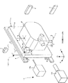
図1は、上流側ステージP1を示す斜視図、図2は、下流側ステージP2のターンテーブル10を回転移動する前の状態を示す斜視図、図3は、下流側ステージP2のターンテーブル10を回転移動させた後の状態を示す斜視図である。 Figure 1 is a perspective view showing an upstream stage P 1, FIG. 2 is a perspective view showing a state before the rotational movement of the turntable 10 on the downstream side stage P 2, FIG. 3, the turn of the downstream stage P 2 It is a perspective view which shows the state after rotating the table 10. FIG.
図1〜図3に示す符号1は、トランスミッションケースWが取り付けられるパレットであり、符号2は、トランスミッションケースWの製造ラインに設けられているパレット搬送レールである。パレット搬送レール2は、製造ラインの上流側ステージP1と下流側ステージP2との間に亘って水平に配設され、互いに上下に離間して対をなし、平行に延在している。
The
パレット1は、一対のパレット搬送レール2に沿って上下方向に起立する略矩形の平板形状を有しており、パレット1の裏面部に設けられた係合爪3により各搬送レール2にそれぞれ係合して搬送レール2に沿って自在に移動できるように構成されている。
The
パレット1の正面部1Aには、トランスミッションケースWを正面部1Aの略中央位置に着脱自在に取り付ける取り付け手段(図示せず)が設けられており、トランスミッションケースWよりも移動方向前方位置には基準ブロック4が突設されている。
The
基準ブロック4は、正面部1Aに直交してパレット1の移動方向(図1で矢印F方向)に沿って延在する上面4a及び下面4cと、パレット1の移動方向に直交して延在する前面4b及び後面4dと、正面部1Aと平行に延在する頭頂面4eを有する立方体形状を有している。尚、本実施の形態では、図2に示すように、後述する下流側ステージP2に設けられているターンテーブル10の回転中心Lに沿って延在しかつ互いに直交する方向に延在する頭頂面4eと前面4bをそれぞれ第1基準面と第2基準面として設定している。
The
上流側ステージP1には、図1に示すように、パレット搬送レール2に沿って移動されるパレット1を予め設定された停止位置に停止させて保持する上流側パレット保持手段(図示せず)と、そのパレット1に取り付けられているトランスミッションケースWに対して、第1軸孔H1を加工形成するための第1軸孔加工機6が設けられている。第1軸孔加工機6は、本実施の形態では、横型マシニングセンタによって構成されており、パレット1の正面部1Aに対向する位置に配置され、パレット1の移動方向に沿って水平に延在するX1軸方向、パレット1の移動方向に直交して水平に延在するY1軸方向、パレット1の移動方向に直交して鉛直方向に延在するZ1軸方向に移動可能な多軸ヘッド6aを備え、多軸ヘッド6aをX1軸方向及びZ1軸方向に沿って移動させてトランスミッションケースWに対する第1軸孔H1の位置決めを行い、Y1軸方向に沿ってパレット1に接近する方向に移動させることによって、トランスミッションケースWに第1軸孔H1を加工形成するように構成されている。
As shown in FIG. 1, the upstream stage P 1 has an upstream pallet holding means (not shown) for holding the
下流側ステージP2には、図2に示すように、パレット搬送レール2に沿って移動されるパレット1を予め設定された停止位置で停止させて保持する下流側パレット保持手段11と、下流側パレット保持手段11を鉛直方向に延在する回転中心Lを中心として回転移動させる回転移動手段12を備えたターンテーブル10が設けられている。
As shown in FIG. 2, the downstream stage P 2 includes a downstream pallet holding means 11 for stopping and holding the
下流側パレット保持手段11は、アクチュエータ11a(図4参照)を備えており、パレット搬送レール2に沿って搬送されてきたパレット1を下流側ステージP2の所定位置に停止させて保持し、また、その保持を解除して更に下流側に搬出することができるように構成されている。そして、回転移動手段12は、ステップモータ12a(図4参照)を備えており、下流側パレット保持手段11を回転移動させると共に、その回転停止位置を精密に制御することができるように構成されている。
Downstream pallet holding means 11 is provided with an
また、下流側ステージP2には、パレット1に取り付けられているトランスミッションケースWに対して、第2軸孔H2を加工形成するための第2軸孔加工機13が設けられている。第2軸孔加工機13は、本実施の形態では、横型マシニングセンタによって構成されており、パレット1の正面部1Aに対向する位置に配置されている。第2軸孔加工機13は、パレット1の移動方向に沿って水平に延在するX2軸方向、パレット1の移動方向に直交して水平に延在するY2軸方向、パレット1の移動方向に直交して鉛直方向に延在するZ2軸方向に自在に移動可能なタッチセンサ13bを有しており、タッチセンサ13bをX2軸方向、Y2軸方向、Z2軸方向に移動させて基準ブロック4やトランスミッションケースWに当接させることにより下流側ステージP2にて予め設定されている基準座標軸に対する座標位置を検出することができるように構成されている。
The downstream stage P 2 is provided with a second shaft
また、第2軸孔加工機13は、X2軸方向、Y2軸方向、Z2軸方向に移動可能な多軸ヘッド13aを備えており、多軸ヘッド13aをX2軸方向及びZ2軸方向に沿って移動させてトランスミッションケースWに対する第2軸孔H2の位置決めを行い、Y2軸方向に沿ってパレット1に接近する方向に移動させることによって、トランスミッションケースWに第2軸孔H2を加工形成できるように構成されている。
The second shaft
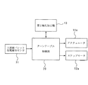
図4は、ターンテーブル10の制御系統を説明するブロック図である。ターンテーブル制御部20は、シーケンスプログラムコンピュータを中心として構成され、その入力側には下流側ステージP2へのパレット1の在席を検知する下流側パレット在席検知センサ31が接続され、出力側には、下流側パレット保持手段11のアクチュエータ11aと回転移動手段12のステップモータ12aが信号ケーブルを介してそれぞれ接続されている。また、第2軸孔加工機13に通信ケーブルを介して接続され、双方向通信可能な構成を有している。
FIG. 4 is a block diagram illustrating a control system of the turntable 10.
ターンテーブル制御部20は、コンピュータに予め記憶されている制御プログラムに従い、下流側パレット在席検知センサ31からの検出信号や第2軸孔加工機13からの制御信号等に基づき、下流側ステージP2におけるパレット1の保持制御や回転停止位置の制御を行うように構成されている。
The
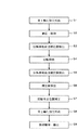
次に、2軸孔加工方法について図5のフローチャートを用いて以下に説明する。 Next, the biaxial hole machining method will be described below using the flowchart of FIG.
まず最初に、上流側ステージP1でトランスミッションケースWに第1軸孔H1を加工形成すべく、トランスミッションケースWが取り付けられたパレット1をパレット搬送レール2の上流側から上流側ステージP1に搬入し、上流側パレット保持手段によって所定位置に保持し(図1参照)、トランスミッションケースWを第1軸孔加工機6に対向配置させる。
First, the upstream-side stage P 1 to be processed form the first shaft hole H 1 to the transmission case W, on the upstream side stage P 1 a
そして、多軸ヘッド6aをY1軸方向とZ1軸方向に移動させてトランスミッションケースWに対する第1軸孔H1の位置決めを行い、Y1軸方向に沿ってパレット1に接近する方向に移動させて、トランスミッションケースWに第1軸孔H1を加工形成する(ステップS1)。このステップが請求項1の第1ステップに相当する。
Then, move the multi-axis head 6a Y 1 is moved in the axial direction and Z 1 axial positioning is performed in the first shaft hole H 1 relative to the transmission case W is, in a direction toward the
トランスミッションケースWに対する第1軸孔H1の加工形成が終了すると、上流側パレット保持手段によるパレット1の保持を解除して下流側ステージP2に搬送し、下流側パレット保持手段11によって下流側ステージP2の所定位置にパレット1を保持し(図2参照)、トランスミッションケースWを第2軸孔加工機13に対向配置させる(ステップS2)。このステップが請求項1の第2ステップに相当する。
When machining forming of the first shaft hole H 1 relative to the transmission case W is completed, it is conveyed to the downstream side stage P 2 to release the holding of the
下流側パレット保持手段11によりパレット1を保持すると、第2軸孔加工機13のタッチセンサ13bを基準ブロック4の第1基準面4eと第2基準面4b、及びトランスミッションケースWの第1軸孔H1に当接させて、これらの座標位置を検出する(ステップS3)。このステップが請求項1の第3ステップに相当する。
When the
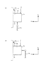
図6は、下流側ステージP2で回転移動前に第1基準面4e、第2基準面4b、第1軸孔H1の各座標位置を検出する方法を説明する図である。まず、図6(a)に示すように、タッチセンサ13bを第1基準面4eに対向させてY2軸方向に沿って接近移動させ、第1基準面4eに当接した座標位置を検出し、コンピュータの記憶手段に記憶させる。次に、図6(b)に示すように、タッチセンサ13bを第2基準面4bに対向させてX2軸方向に沿って接近移動させ、第2基準面4bに当接した座標位置を検出し、コンピュータの記憶手段に記憶させる。
Figure 6 is a diagram illustrating a method for detecting a rotation
それから、タッチセンサ13bを第1軸孔H1内に挿入し、第1軸孔H1の軸方向手前側と奥側でそれぞれX2軸方向に沿って接近移動させる。そして、第1軸孔H1に当接した座標位置を検出し、所定の演算処理により第1軸孔H1の座標位置を算出してコンピュータの記憶手段に記憶させる。
Then, insert the
ターンテーブル制御部20は、回転移動前の第1基準面4e、第2基準面4b、第1軸孔H1の各座標位置を検出してコンピュータの記憶手段に記憶すると、回転移動手段12のステップモータ12aに所定の駆動信号を出力して下流側パレット保持手段11をパレット1と共に回転移動させ、図3に示すように、90°だけ左回りに回転移動させた回転停止位置に配置する(ステップS4)。このステップが請求項1の第4ステップに相当する。
そして、第2軸孔加工機13のタッチセンサ13bを基準ブロック4の第1基準面4eと第2基準面4bに当接させて、これらの座標位置を検出する(ステップS5)。このステップが請求項1の第5ステップに相当する。
Then, the
図7は、下流側ステージP2で回転移動後に第1基準面4eと第2基準面4bの各座標位置を検出する方法を説明する図である。まず、図7(a)に示すように、タッチセンサ13bを第2基準面4bに対向させてY2軸方向に沿って接近移動させ、第2基準面4bに当接した座標位置を検出し、コンピュータの記憶手段に記憶させる。次に、図7(b)に示すように、タッチセンサ13bを第1基準面4eに対向させてX2軸方向に沿って接近移動させ、第1基準面4eに当接した座標位置を検出し、コンピュータの記憶手段に記憶させる。
Figure 7 is a diagram for explaining a method of detecting the coordinate position of the
ターンテーブル制御部20は、回転移動後における第1基準面4eと第2基準面4bの各座標位置の検出が終了すると、パレット1の回転停止位置を補正する補正値の算出を行う(ステップS6)。このステップが請求項1の第6ステップに相当する。
When the
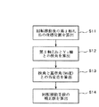
図8は、補正値算出方法を説明するフローチャートである。ここでは、まず最初に回転移動後の第1基準面4eと第2基準面4bの各座標位置に基づいて、回転移動後の第1軸孔H1の座標位置を算出する(ステップS11)。そして、回転移動後の第1軸孔H1の座標位置と第2軸孔加工機13の座標位置とを用いて、水平面上で第1軸孔H1の軸心と第2軸孔加工機13の軸心であるY2軸との間に形成される挟角γを算出する(ステップS12)。それから、予め設定されている基準角である90°と挟角γとの角度差δを算出する(ステップS13)。そして、その角度差を0°とするために、回転移動手段12による下流側パレット保持手段11の回転停止位置を補正する補正値を算出する(ステップS14)。
FIG. 8 is a flowchart illustrating a correction value calculation method. Here, first of all the
ターンテーブル制御部20は、上記補正値算出方法に基づいて補正値を算出すると、その補正値を用いて下流側パレット保持手段11の回転停止位置を補正する制御を行う(ステップS7)。このステップが請求項1の第7ステップに相当する。
After calculating the correction value based on the correction value calculation method, the
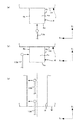
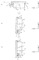
図9及び図10は、下流側ステージP2で下流側パレット保持手段11の回転停止位置を補正する方法を説明する図である。まず最初に、図9に示す場合を例に説明すると、例えば、下流側ステージP2で回転移動前に基準ブロック4の第1基準面4eと第2基準面4b、及び第1軸孔H1の座標位置を検出した結果、図9(a)に示すように、トランスミッションケースWの第1軸孔H1が基準ブロック4の第1基準面4eに直交する方向に沿って延在するように加工形成されており、第1軸孔H1がY2軸方向に沿って配置されていたとする。
9 and 10 are views for explaining a method of correcting a rotation stop position of the downstream pallet holding means 11 at the downstream side stage P 2. First, to describe an example case shown in FIG. 9, for example, downstream stage P 2 in the
次いで、パレットを90°だけ回転移動させ、回転後の回転停止位置で第1基準面4eと第2基準面4bの座標位置を検出する。ここで、回転移動手段12の停止精度誤差等により、図9(b)に示すように、パレット1が90°よりも小さい角度だけ回転移動していた場合には、回転後の第1軸孔H1と第2軸孔加工機13のY2軸との間に形成される挟角γ1が90°よりも狭い角度となる。
Next, the pallet is rotated by 90 °, and the coordinate positions of the
従って、ターンテーブル制御部20は、その挟角γ1と予め設定されている角度である90°との角度差δ1を算出し、その角度差δ1を0°とするための補正値を算出し、ステップモータ12aに出力する。ステップモータ12aは、ターンテーブル制御部20から入力した補正値に基づいて、角度差δ1が0°となる方向に所定角度だけ下流側パレット保持手段11を回転移動させ、図9(c)に示すように、第2軸孔加工機13のY2軸が第1軸孔H1に対して直交する回転停止位置に配置する。
Therefore, the
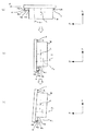
次に、図10に示す場合を例に説明すると、例えば、図10(a)に示すように、下流側ステージP2で回転前に基準ブロック4の第1基準面4eと第2基準面4b、及び第1軸孔H1の座標位置を検出する。ここでは、例えば、上流側ステージP1における第1軸孔H1のトランスミッションケースWに対する加工精度誤差等により、トランスミッションケースWの第1軸孔H1が、基準ブロック4の第1基準面4eに直交せず、傾斜して延在する方向に加工形成されていたとする。
Next, will be described as an example a case shown in FIG. 10, for example, as shown in FIG. 10 (a), the
次いで、パレットを90°だけ回転移動させ、回転後の回転停止位置で第1基準面4eと第2基準面4bの座標位置を検出する。ここで、回転移動手段12が下流側パレット保持手段11を正確に90°だけ回転移動させた場合、図10(b)に示すように、回転後の第1軸孔H1と第2軸孔加工機13のY2軸との間に形成される挟角γ2は90°よりも大きい角度となる。
Next, the pallet is rotated by 90 °, and the coordinate positions of the
従って、ターンテーブル制御部20は、その挟角γ2と予め設定されている角度である90°との角度差δ2を算出し、その角度差δ2を0°とするための補正値を算出し、ステップモータ12aに出力する。ステップモータ12aは、ターンテーブル制御部20から入力した補正値に基づいて、角度差δ2が0°となる方向に所定角度だけ下流側パレット保持手段11を回転移動させ、図10(c)に示すように、第2軸孔加工機13のY2軸が第1軸孔H1に対して直交する回転停止位置に配置する。
Therefore, the
回転移動手段12により第2軸孔加工機13のY2軸が第1軸孔H1に対して直交する回転停止位置に下流側パレット保持手段11を配置すると、第2軸孔加工機13の多軸ヘッド13aをX2軸方向とZ2軸方向に移動させてトランスミッションケースWに対する第2軸孔H2の位置決めを行い、Y2軸に沿って接近移動させて第2軸孔H2をトランスミッションケースWに加工形成する(ステップS8)。このステップが請求項1の第8ステップに相当する。
When the rotational moving means 12 is Y 2 axis of the second shaft
以上の動作により、トランスミッションケースWに第1軸孔H1と第2軸孔H2とからなる高精度の直角度を有する直交軸孔Hを加工形成することができる。そして、トランスミッションケースWに直交軸孔Hを加工形成すると、回転移動手段12により下流側パレット保持手段11を回転移動させて、パレット搬送レール2に沿う回転停止位置に配置し、下流側ステージP2におけるパレット1の保持を解除し、パレット1を搬出する(ステップS9)。
By the above operation, an orthogonal shaft hole H having a straight angle with high accuracy comprising the first shaft hole H 1 and the second shaft hole H 2 Metropolitan the transmission case W can be processed and formed. When the orthogonal shaft hole H is machined and formed in the transmission case W, the rotary pallet holding means 11 is rotated by the rotary moving means 12 and arranged at the rotation stop position along the
上述の2軸孔加工方法によれば、下流側ステージP2で第2軸孔加工機13によりトランスミッションケースWに第2軸孔H2を加工形成する前に、回転移動手段12による下流側パレット保持手段11の回転停止位置を補正し、補正後にトランスミッションケースWに第2軸孔H2を加工形成するので、第1軸孔H1と第2軸孔H2が互いに高精度の直角度で直交する直交軸孔Hを得ることができ、直交軸孔Hの加工精度を向上させることができる。
According to the two axial hole machining method described above, before the second shaft hole H 2 is processed and formed in the transmission case W by the second shaft
特に、下流側パレット保持手段11を回転移動させる前に検出した第1基準面4e、第2基準面4b、第1軸孔H1の各座標位置と、回転移動後に検出した第1基準面4e及び第2基準面4bの各座標位置とに基づいて、回転停止位置における第1軸孔H1の座標位置を求め、その回転停止位置における第1軸孔H1の軸心と第2軸孔加工機13の軸心であるY2軸との挟角γを求めて、この挟角γを基準角である90°と対比することによって、その角度差δを認識することができ、角度差δに基づいて回転移動手段12による下流側パレット保持手段11の回転停止位置を補正する補正値を容易に得ることができ、回転停止位置を迅速に補正することができる。従って、第1軸孔H1と第2軸孔H2との挟角γが90°に等しい正確な直交軸孔HをトランスミッションケースWに迅速かつ容易に加工形成することができる。
Particularly, the
尚、本発明は、上述の実施の形態に限定されるものではなく、本発明の趣旨を逸脱しない範囲で種々の変更が可能である。例えば、上述の実施の形態では、トランスミッションケースWに対して第1軸孔H1と第2軸孔H2の各軸心が互いに直交する直交軸孔Hを加工形成する場合を例に説明したが、予め設定されている角度であれば、いかなる角度であってもよく、また、第1軸孔H1の軸心と第2軸孔H2の軸心は必ず交差する必要はなく、上下方向に離間している場合であってもよい。 In addition, this invention is not limited to the above-mentioned embodiment, A various change is possible in the range which does not deviate from the meaning of this invention. For example, in the above embodiment has been described the case of forming processing an orthogonal shaft hole H of the first shaft hole H 1 and the axis of the second shaft hole H 2 are perpendicular to each other with respect to the transmission case W Examples but if the angle is set in advance, it may be any angle, also, the first shaft hole H 1 axis and the axis of the second shaft hole H 2 need not always intersect, vertical It may be a case where they are separated in the direction.
また、第1基準面4eと第2基準面4bは、回転移動前と回転移動後の座標位置を検出することによって、回転停止位置における第1軸孔H1の座標位置を算出することができればよく、必ずしも直角度を有する必要はない。
The
1 パレット
4 基準ブロック
4b 第2基準面
4e 第1基準面4e
6 第1軸孔加工機
10 ターンテーブル
11 下流側パレット保持手段
12 回転移動手段
12a ステップモータ
13 第2軸孔加工機
13a 多軸ヘッド
13b タッチセンサ
31 下流側パレット在席検知センサ
P1 上流側ステージ
P2 下流側ステージ
W トランスミッションケース(ワーク)
H 直交軸孔(2軸孔)
H1 第1軸孔
H2 第2軸孔
1
6 First shaft hole processing machine 10
H orthogonal shaft hole (biaxial hole)
H 1 1st shaft hole H 2 2nd shaft hole
Claims (2)
前記上流側ステージで前記ワークに第1軸孔加工機により第1軸孔を加工形成する第1ステップと、
前記上流側ステージから前記下流側ステージに搬送されてきた前記パレットを前記下流側ステージに設けられている下流側パレット保持手段で保持する第2ステップと、
前記パレットに形成されている第1基準面及び第2基準面の各座標位置と、前記ワークの第1軸孔の座標位置とをそれぞれ検出する第3ステップと、
回転移動手段により前記下流側パレット保持手段を所定角度だけ回転移動させて予め設定されている回転停止位置に配置する第4ステップと、
前記回転停止位置で前記パレットの第1基準面と第2基準面の各座標位置を検出する第5ステップと、
回転移動前の第1基準面と第2基準面と第1軸孔の各座標位置、及び回転移動後の第1基準面と第2基準面の各座標位置に基づいて、回転移動手段による下流側パレット保持手段の回転停止位置を補正する補正値を算出する第6ステップと、
該算出した補正値に基づいて前記回転移動手段により下流側パレット保持手段を回転移動させる第7ステップと、
第2軸孔加工機により前記ワークに前記第2軸孔を加工形成する第8ステップと、
を有することを特徴とする2軸孔加工方法。 A first shaft hole is formed in a workpiece attached to the pallet in the upstream stage, the workpiece is transported together with the pallet from the upstream stage to the downstream stage, and the workpiece is moved to the second axis on the downstream stage. In the biaxial hole machining method for machining and forming holes,
A first step of forming a first shaft hole on the workpiece on the upstream stage by a first shaft hole processing machine;
A second step of holding the pallet conveyed from the upstream stage to the downstream stage by a downstream pallet holding means provided in the downstream stage;
A third step of detecting the respective coordinate positions of the first reference surface and the second reference surface formed on the pallet and the coordinate position of the first shaft hole of the workpiece;
A fourth step of rotating the downstream pallet holding means by a predetermined angle by a rotational movement means and disposing it at a preset rotation stop position;
A fifth step of detecting each coordinate position of the first reference surface and the second reference surface of the pallet at the rotation stop position;
Based on the respective coordinate positions of the first reference surface, the second reference surface and the first shaft hole before the rotational movement, and the respective coordinate positions of the first reference surface and the second reference surface after the rotational movement, the downstream by the rotational movement means. A sixth step of calculating a correction value for correcting the rotation stop position of the side pallet holding means;
A seventh step of rotating the downstream pallet holding means by the rotational movement means based on the calculated correction value;
An eighth step of machining and forming the second shaft hole in the workpiece by a second shaft hole processing machine;
A biaxial hole machining method comprising:
前記回転移動前に検出した第1基準面、第2基準面、第1軸孔の各座標位置と、前記回転移動後に検出した前記第1基準面、前記第2基準面の各座標位置とに基づいて前記回転停止位置における前記第1軸孔の座標位置を算出し、
前記回転停止位置における第1軸孔の軸心と第2軸孔加工機の軸心との間に形成される挟角を算出し、
該算出した挟角と予め設定されている基準角との角度差を算出し、
該算出した角度差に基づいて前記補正値を算出することを特徴とする請求項1に記載の2軸孔加工方法。 In the sixth step,
The coordinate positions of the first reference plane, the second reference plane, and the first shaft hole detected before the rotational movement, and the coordinate positions of the first reference plane and the second reference plane detected after the rotational movement. And calculating the coordinate position of the first shaft hole at the rotation stop position based on
Calculating the included angle formed between the shaft center of the first shaft hole and the shaft center of the second shaft hole processing machine at the rotation stop position;
Calculating an angle difference between the calculated included angle and a preset reference angle;
The biaxial drilling method according to claim 1, wherein the correction value is calculated based on the calculated angle difference.
Priority Applications (1)
| Application Number | Priority Date | Filing Date | Title |
|---|---|---|---|
| JP2004115267A JP2005297112A (en) | 2004-04-09 | 2004-04-09 | Biaxial drilling method |
Applications Claiming Priority (1)
| Application Number | Priority Date | Filing Date | Title |
|---|---|---|---|
| JP2004115267A JP2005297112A (en) | 2004-04-09 | 2004-04-09 | Biaxial drilling method |
Publications (1)
| Publication Number | Publication Date |
|---|---|
| JP2005297112A true JP2005297112A (en) | 2005-10-27 |
Family
ID=35329280
Family Applications (1)
| Application Number | Title | Priority Date | Filing Date |
|---|---|---|---|
| JP2004115267A Pending JP2005297112A (en) | 2004-04-09 | 2004-04-09 | Biaxial drilling method |
Country Status (1)
| Country | Link |
|---|---|
| JP (1) | JP2005297112A (en) |
Cited By (6)
| Publication number | Priority date | Publication date | Assignee | Title |
|---|---|---|---|---|
| JP2011240466A (en) * | 2010-05-21 | 2011-12-01 | Honda Motor Co Ltd | Machining method and machining device |
| CN102266958A (en) * | 2011-07-07 | 2011-12-07 | 上海交通大学 | Flexible guide rail hole group machining method based on drilling equipment coordinate system determination |
| CN111469125A (en) * | 2020-04-01 | 2020-07-31 | 南京浦航机械科技开发有限公司 | Hole site correction method applied to automatic drilling and riveting of curved surface product |
| CN111702427A (en) * | 2020-07-04 | 2020-09-25 | 无锡市高田机械有限公司 | A kind of intelligent automatic transmission processing and development process |
| CN114594729A (en) * | 2022-02-17 | 2022-06-07 | 成都飞机工业(集团)有限责任公司 | Double-sided part machining reference correction method |
| CN116586662A (en) * | 2023-05-11 | 2023-08-15 | 上海电气上重铸锻有限公司 | A reference design method for zero-degree shaft hole machining of super large special-shaped parts |
-
2004
- 2004-04-09 JP JP2004115267A patent/JP2005297112A/en active Pending
Cited By (7)
| Publication number | Priority date | Publication date | Assignee | Title |
|---|---|---|---|---|
| JP2011240466A (en) * | 2010-05-21 | 2011-12-01 | Honda Motor Co Ltd | Machining method and machining device |
| CN102266958A (en) * | 2011-07-07 | 2011-12-07 | 上海交通大学 | Flexible guide rail hole group machining method based on drilling equipment coordinate system determination |
| CN111469125A (en) * | 2020-04-01 | 2020-07-31 | 南京浦航机械科技开发有限公司 | Hole site correction method applied to automatic drilling and riveting of curved surface product |
| CN111702427A (en) * | 2020-07-04 | 2020-09-25 | 无锡市高田机械有限公司 | A kind of intelligent automatic transmission processing and development process |
| CN114594729A (en) * | 2022-02-17 | 2022-06-07 | 成都飞机工业(集团)有限责任公司 | Double-sided part machining reference correction method |
| CN114594729B (en) * | 2022-02-17 | 2024-03-15 | 成都飞机工业(集团)有限责任公司 | Double-sided part machining reference correction method |
| CN116586662A (en) * | 2023-05-11 | 2023-08-15 | 上海电气上重铸锻有限公司 | A reference design method for zero-degree shaft hole machining of super large special-shaped parts |
Similar Documents
| Publication | Publication Date | Title |
|---|---|---|
| JP4291382B2 (en) | Machine tool with automatic correction function of mounting error by contact detection | |
| JP6816060B2 (en) | Work robot system and work robot | |
| JP6849631B2 (en) | Work robot system and work robot | |
| US20150160049A1 (en) | Geometric error identification method of multi-axis machine tool and multi-axis machine tool | |
| US9782899B2 (en) | Calibration method for coordinate system of robot manipulator | |
| JP4276270B2 (en) | Machine tool with workpiece reference position setting function by contact detection | |
| CN107303644B (en) | Method and system for measuring position of object on machine tool | |
| JP6748126B2 (en) | Work robot system | |
| JP2019086823A (en) | Machining system | |
| JP2017194451A (en) | Error identification method and error identification system for machine tools | |
| US20180361587A1 (en) | Calibrating A System With A Conveying Means And At Least One Robot | |
| JP6803043B2 (en) | How to measure geometric error of machine tools | |
| CN112439984A (en) | Plasma torch cutting system | |
| KR101809244B1 (en) | Five-axis cnc machine calibration method using calibration jig | |
| JP6088190B2 (en) | Processing system and processing method thereof | |
| JP2005297112A (en) | Biaxial drilling method | |
| JP4082598B2 (en) | Method and apparatus for correcting thermal displacement of numerically controlled machine tool | |
| JP6647308B2 (en) | Teaching system of articulated robot | |
| JP4898290B2 (en) | Work transfer device with electric chuck with measurement function | |
| US20200206861A1 (en) | Method for determining the topography of a machine tool | |
| JP3660920B2 (en) | Machine tool and processing method | |
| JP2007257606A (en) | Tool positioning error compensation method | |
| JP5118896B2 (en) | Transfer robot system | |
| JP6245995B2 (en) | Tool tip position detection method and detection device | |
| JP6623061B2 (en) | Machine tool and control method of machine tool |