JP2005297101A - Cutting position detecting device of traveling sheet - Google Patents
Cutting position detecting device of traveling sheet Download PDFInfo
- Publication number
- JP2005297101A JP2005297101A JP2004114394A JP2004114394A JP2005297101A JP 2005297101 A JP2005297101 A JP 2005297101A JP 2004114394 A JP2004114394 A JP 2004114394A JP 2004114394 A JP2004114394 A JP 2004114394A JP 2005297101 A JP2005297101 A JP 2005297101A
- Authority
- JP
- Japan
- Prior art keywords
- sheet
- mark
- traveling
- width
- width direction
- Prior art date
- Legal status (The legal status is an assumption and is not a legal conclusion. Google has not performed a legal analysis and makes no representation as to the accuracy of the status listed.)
- Pending
Links
- 230000000007 visual effect Effects 0.000 claims abstract description 9
- 238000001514 detection method Methods 0.000 claims description 23
- 238000003384 imaging method Methods 0.000 claims description 15
- 239000000463 material Substances 0.000 description 6
- 239000000123 paper Substances 0.000 description 4
- 238000011144 upstream manufacturing Methods 0.000 description 2
- 230000010485 coping Effects 0.000 description 1
- 238000009434 installation Methods 0.000 description 1
- 238000004519 manufacturing process Methods 0.000 description 1
- 239000007787 solid Substances 0.000 description 1
Images
Landscapes
- Control Of Cutting Processes (AREA)
Abstract
Description
本発明は、走行シートを長さ切断する切断位置の目安とされるピッチマークの付与位置を検出する走行シートの切断位置検出装置に関するものである。 The present invention relates to a traveling sheet cutting position detection device that detects a position where a pitch mark is applied, which is a guide for a cutting position for cutting a traveling sheet in length.
高速で走行する段ボールシートや厚紙等の走行シートを長さ切断する際には、予め走行シートに走行方向で所定の間隔を設けてピッチマークを付与し、このピッチマークの付与位置を切断位置の目安とすることがある。このような走行シートを長さ切断する前には幅切り切断が行われることが多く、この幅切り切断位置の目安として、シート幅縁部に走行方向へ延びるラインマークが付与され、ピッチマークはラインマークからシート内側へ所定の長さだけ幅方向に連続するように付与される。 When a traveling sheet such as a cardboard sheet or cardboard traveling at high speed is cut in length, a pitch mark is previously provided on the traveling sheet with a predetermined interval in the traveling direction, and the position at which the pitch mark is applied is determined as the cutting position. It may be a guide. Before such a traveling sheet is cut into lengths, a width cut is often performed, and as a guideline for the width cutting position, a line mark extending in the running direction is given to the sheet width edge, and the pitch mark is It is applied so as to continue in the width direction by a predetermined length from the line mark to the inside of the sheet.
例えば、本発明の実施形態で対象とするコルゲートマシンで製造される段ボールシートには、図2に示すように、表ライナ紙2に予め印刷模様3がその走行方向に所定のピッチでプレプリントされ、さらに、この印刷模様3のピッチに合わせて所定の間隔で印刷された長さ切断位置の目安とされるピッチマーク4と、一方の幅縁部に沿って印刷された幅切り切断位置の目安とされるラインマーク5とが付与されたものがある。この例では、ピッチマーク4が2つ一組のマーク素子4aで形成されている。ピッチマーク4は1つまたは3つ以上のマーク素子4aで形成されることもあり、ラインマーク5は両方の幅縁部に付与されることもある。
For example, as shown in FIG. 2, a printed pattern 3 is pre-printed on a
図2に示したような段ボールシート1を製造するコルゲートマシンでは、本発明の実施形態を説明する図1に示すように、幅切り切断用のスリッタ6と長さ切断用のロータリカッタ7とが順に配設され、高速で走行してくる段ボールシート1を先にスリッタ6で走行方向に幅切り切断したのち、ロータリカッタ7の上流側に設けたマーク検出手段でピッチマーク4を検出して、この検出出力に基づいてロータリカッタ7の切断タイミングを制御している。なお、段ボールシート1の製造ラインでは、表ライナ紙2は段ボールシート1の下面側に位置するので、マーク検出手段は走行する段ボールシート1の下面側に配置される。
In the corrugating machine for producing the
このようなラインマークとピッチマークを付与された走行シートの長さ切断では、シートの汚れや印刷模様がピッチマークとして誤検出され、走行シートが誤った位置で長さ切断される問題があった。この問題に対処する走行材料のマーク検出装置として、ピッチマークを走行材料の所定位置に所定幅で所定数のマーク素子を付与したものとし、ピッチマークを所定の幅方向位置で検出するセンサと、走行材料の走行量を検出する走行量検出器と、センサがマーク素子や印刷部分の検出出力に相当するハイレベルの被検出部を検出しているときの走行量がマーク素子幅に対応する設定範囲内にあるときのみ一致信号を発するマーク素子幅判別器と、センサが被検出部の検出を完了し、続く非検出状態での走行量が所定の設定範囲内にないときのみ不一致信号を発するマーク間隙幅判別器と、マーク素子幅判別器から入力される一致信号を計数し、マーク間隙幅判別器からの不一致信号が入力された場合は新たにマーク素子幅判別器からの一致信号を計数し、その計数値が所定のマーク素子数になると、マーク検出信号を出力するマーク素子数判別器とを備え、ピッチマークをシートの汚れや印刷模様と識別するようにしたものがある(例えば、特許文献1参照。)。 In the length cutting of the traveling sheet to which such a line mark and a pitch mark are given, there is a problem that the stain or the printed pattern of the sheet is erroneously detected as the pitch mark, and the traveling sheet is cut at the wrong position. . As a traveling material mark detection device for coping with this problem, a sensor for detecting a pitch mark at a predetermined position in the width direction, with a pitch mark having a predetermined width and a predetermined number of mark elements at a predetermined position of the traveling material, A travel amount detector that detects the travel amount of the travel material, and a setting that corresponds to the mark element width when the sensor detects a high-level detected part corresponding to the detection output of the mark element or the printed part. A mark element width discriminator that emits a coincidence signal only when it is within the range, and a sensor that completes detection of the detected portion and issues a discrepancy signal only when the travel amount in the subsequent non-detection state is not within the predetermined setting range The coincidence signals input from the mark gap width discriminator and the mark element width discriminator are counted, and when a mismatch signal is input from the mark gap width discriminator, a new coincidence from the mark element width discriminator A mark element number discriminator for outputting a mark detection signal when the count value reaches a predetermined number of mark elements, and for identifying pitch marks from dirt and printed patterns on a sheet. (For example, refer to Patent Document 1).
また、走行シートにピッチマークと印刷または加工等が施された部位を被検出体としてこの被検出体を2次元の撮像手段で撮像し、その2次元の撮像画面を画像処理してピッチマークを印刷模様等と識別するようにしたものもある(例えば、特許文献2参照。)。特許文献2に記載のものでは、ピッチマークの不検出が起こらないように、各撮像画面が走行方向で前後の撮像画面と一部重複するようにしている。
In addition, a portion of the traveling sheet that has been printed or processed with a pitch mark is taken as an object to be detected, and the detected object is imaged by a two-dimensional imaging means, and the two-dimensional imaging screen is subjected to image processing to obtain the pitch mark. Some are identified as a printed pattern or the like (for example, see Patent Document 2). In the device described in
特許文献1に記載された走行材料のマーク検出装置は、ピッチマークを検出するセンサは1点を検出するのみの簡単なものとすることができるが、走行材料が幅方向にずれてピッチマークが不検出となる恐れがある。また、マーク素子の幅やマーク素子間の間隙を検出するために、センサの他に走行材料の走行量を高い精度で検出できる走行量検出器を必要とし、マーク検出装置の構成が複雑なものとなる問題もある。
In the traveling material mark detection apparatus described in
一方、特許文献2に記載のものは、ピッチマークの不検出が生じる恐れは少ないが、ピッチマークの検出に2次元の撮像手段を用いているので、その画像処理とピッチマークの識別に時間がかかり、コルゲートマシンで製造される段ボールシートのように高速で走行する走行シートに対しては、カッタへの切断位置の検出出力が間に合わなくなる恐れがある。
On the other hand, although the thing of
そこで、本発明の課題は、走行シートに付与された長さ切断位置の目安としてのピッチマークを、短時間で確実に識別できるようにすることである。 Therefore, an object of the present invention is to make it possible to reliably identify a pitch mark as a guide for a length cutting position given to a traveling sheet in a short time.
上記の課題を解決するために、本発明は、少なくとも一方のシート幅縁部に走行方向へ延びるラインマークが付与され、さらに、このラインマークからシート内側へ所定の長さだけ幅方向に連続するピッチマークが走行方向で所定の間隔を設けて付与された走行シートの走行方向切断位置を、前記ピッチマークの付与位置として検出する走行シートの切断位置検出装置において、前記走行シートのラインマークとピッチマークが付与されたシート幅縁部と、このシート幅縁部の外側のシート外側部とを含めた幅方向の視野を連続的に撮影する一次元撮影装置を設け、この一次元撮影装置で撮影された視野の各幅方向部位での出力を明部と暗部に2値化する画像処理を行い、この画像処理された一次元の2値化データについて、前記走行シートの走行方向で暗部が連続する最もシート内方側の幅方向部位に、そのシート内側へ幅方向に連続する暗部が存在する走行方向位置を、前記ピッチマークの付与位置として検出する構成を採用した。 In order to solve the above-described problems, in the present invention, a line mark extending in the running direction is given to at least one sheet width edge portion, and further, the line mark is continuous in the width direction by a predetermined length from the line mark to the inside of the sheet. In the traveling sheet cutting position detecting device for detecting a traveling direction cutting position of a traveling sheet provided with a predetermined interval in the traveling direction as a pitch mark application position, the line mark and pitch of the traveling sheet are detected. A one-dimensional imaging device is provided for continuously photographing the visual field in the width direction including the sheet width edge portion to which the mark is added and the sheet outer edge portion outside the sheet width edge portion. Image processing for binarizing the output in each width direction portion of the visual field into a bright part and a dark part, and the traveling sheet for the one-dimensional binarized data subjected to the image processing Most sheet inner side in the width direction portions dark portion is continuous with the running direction, the driving direction position there is a dark portion continuous to the sheet inward in the width direction, and employs a configuration of detecting the assigned position of the pitch mark.
すなわち、走行シートのラインマークとピッチマークが付与されたシート幅縁部と、このシート幅縁部の外側のシート外側部とを含めた幅方向の視野を連続的に撮影する一次元撮影装置を設け、この一次元撮影装置で撮影された視野の各幅方向部位での出力を明部と暗部に2値化する画像処理を行い、この画像処理された一次元の2値化データについて、走行シートの走行方向で暗部が連続する最もシート内方側の幅方向部位に、そのシート内側へ幅方向に連続する暗部が存在する走行方向位置を、ピッチマークの付与位置として検出することにより、ピッチマークがラインマークのシート内側へ幅方向に連続することを利用して、簡単な一次元の画像処理でピッチマークを短時間で確実に識別できるようにした。なお、前記2値化画像処理では、ラインマークやピッチマークの付与部位、シートの汚れや印刷模様の部位、およびシート外側部が暗部となり、その他の部位は明部となる。 That is, a one-dimensional imaging device that continuously images a visual field in a width direction including a sheet width edge portion to which a line mark and a pitch mark of a traveling sheet are provided and a sheet outer portion outside the sheet width edge portion. Provided, image processing is performed to binarize the output in each width direction portion of the field of view imaged by the one-dimensional imaging device into a bright part and a dark part, and the one-dimensional binary data subjected to the image processing is run By detecting the running direction position where the dark part continuous in the width direction on the inner side of the sheet exists in the width direction part where the dark part is continuous in the running direction of the sheet as the pitch mark application position, By using the fact that the marks continue in the width direction inside the sheet of the line marks, the pitch marks can be reliably identified in a short time by simple one-dimensional image processing. In the binarized image processing, a line mark or pitch mark application site, a sheet stain or print pattern site, and a sheet outer side portion are dark portions, and other portions are bright portions.
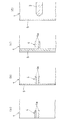
前記一次元撮影装置の撮影視野をシート外側部まで含めたのは、走行シートのラインマークが先の幅切り切断によって完全に除去された場合であっても、一次元の2値化データに走行シートの走行方向で暗部の連続する幅方向部位が存在するようにするためである。つまり、図1に示したように、走行シートとしての段ボールシート1を先に幅切り切断する場合は、図3(a)、(b)、(c)に示すように、幅切り切断位置の目安となるラインマーク5に対して、実際の幅切り切断位置が変動することがある。通常は、図3(b)に示すように、段ボールシート1はラインマーク5上で幅切り切断されることが多いが、図3(a)に示すように、ラインマーク5の内側で幅切り切断されたり、図3(c)に示すように、ラインマーク5の外側で幅切り切断されることがある。
The field of view of the one-dimensional imaging device is included up to the outer part of the sheet, even when the line mark of the traveling sheet is completely removed by the previous width cutting, the traveling to the one-dimensional binary data This is so that there are continuous dark portions in the running direction of the sheet. That is, as shown in FIG. 1, when the
したがって、図3(a)に示したように、ラインマーク5の内側で幅切り切断され、ラインマーク5が完全に除去された場合であっても、前記撮影視野に入るシート外側部が走行方向で暗部の連続する幅方向部位となって1箇所存在し、この幅方向部位からシート内側へ所定の数値範囲内の長さで幅方向に連続する暗部が存在する走行方向位置がピッチマーク4の付与位置として識別される。
Therefore, as shown in FIG. 3 (a), even when the
なお、図3(b)に示したように、ラインマーク5上で幅切り切断された場合は、シート外側部とラインマーク5の部位の走行方向で連続する暗部が合体して1箇所となり、そのシート内側へ幅方向に連続する前記暗部が存在する走行方向位置がピッチマーク4の付与位置として識別される。また、図3(c)に示したように、ラインマーク5の外側で幅切り切断され、その外側に無地の余裕代がある場合は、暗部が走行方向で連続する幅方向部位がシート外側部とラインマーク5の部位との2箇所に存在し、最もシート内方側で暗部が連続する幅方向部位となるラインマーク5の部位からシート内側へ幅方向に連続する前記暗部が存在する走行方向位置がピッチマーク4の付与位置として識別される。
In addition, as shown in FIG.3 (b), when the width cut is carried out on the
前記走行方向で暗部が連続する最もシート内方側の幅方向部位のシート内側へ幅方向に連続する暗部の連続長さが所定の数値範囲内であるときに、この暗部が存在する走行方向位置を、前記ピッチマークの付与位置として検出することにより、ピッチマークが所定の長さで幅方向に連続して付与されることを利用して、より確実にピッチマークを識別することができる。 The running direction position where the dark part exists when the continuous length of the dark part continuous in the width direction to the inside of the sheet in the width direction portion on the innermost side of the sheet where the dark part continues in the running direction is within a predetermined numerical range. Is detected as the pitch mark application position, the pitch mark can be more reliably identified by utilizing the fact that the pitch mark is continuously applied in the width direction with a predetermined length.
この発明の走行シートの切断位置検出装置は、走行シートのラインマークとピッチマークが付与されたシート幅縁部と、このシート幅縁部の外側のシート外側部とを含めた幅方向の視野を連続的に撮影する一次元撮影装置を設け、この一次元撮影装置で撮影された視野の各幅方向部位での出力を明部と暗部に2値化する画像処理を行い、この画像処理された一次元の2値化データについて、走行シートの走行方向で暗部が連続する最もシート内方側の幅方向部位に、そのシート内側へ幅方向に連続する暗部が存在する走行方向位置を、ピッチマークの付与位置として検出するようにしたので、簡単な一次元の画像処理でピッチマークを短時間で確実に識別することができる。 The traveling sheet cutting position detecting device according to the present invention has a visual field in the width direction including a sheet width edge portion to which a line mark and a pitch mark of a traveling sheet are provided, and a sheet outer portion outside the sheet width edge portion. A one-dimensional imaging device for continuous imaging is provided, and image processing is performed to binarize the output in each width direction portion of the visual field captured by this one-dimensional imaging device into a bright part and a dark part. For one-dimensional binarized data, a pitch mark indicates the running direction position where the dark part continuous in the width direction exists on the inner side of the sheet at the innermost side in the width direction where the dark part continues in the running direction of the running sheet. Therefore, the pitch mark can be reliably identified in a short time by simple one-dimensional image processing.
前記走行方向で暗部が連続する最もシート内方側の幅方向部位のシート内側へ幅方向に連続する暗部の連続長さが所定の数値範囲内であるときに、この暗部が存在する走行方向位置をピッチマークの付与位置として検出することにより、ピッチマークが所定の長さで幅方向に連続して付与されることを利用して、より確実にピッチマークを識別することができる。 The running direction position where the dark part exists when the continuous length of the dark part continuous in the width direction to the inside of the sheet in the width direction portion on the innermost side of the sheet where the dark part continues in the running direction is within a predetermined numerical range. Is detected as the pitch mark application position, and the pitch mark can be more reliably identified by utilizing the fact that the pitch mark is continuously applied in the width direction with a predetermined length.
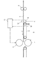
以下、図面に基づき、この発明の実施形態を説明する。図1は、本発明に係る走行シートの切断位置検出装置を採用した、コルゲートマシンで製造される走行シートとしての段ボールシート1を走行方向に幅切り切断するスリッタ6と、幅切り切断された段ボールシート1をこれの幅方向に長さ切断するロータリカッタ7の部分を示す。
Hereinafter, embodiments of the present invention will be described with reference to the drawings. FIG. 1 shows a slitter 6 that cuts a
前記ロータリカッタ7の上流側には、本発明に係る走行シートの切断位置検出装置を構成する一次元撮影装置としての一次元CCDカメラ8が設けられ、ロータリカッタ7の入側コンベア9には、段ボールシート1の搬送速度Vを検出する回転計10が取り付けられている。一次元CCDカメラ8と回転計10の検出出力はコントローラ11に入力されるようになっており、コントローラ11は、後述するように一次元CCDカメラ8の検出出力を画像処理してピッチマーク4の付与位置を識別するとともに、一次元CCDカメラ8とロータリカッタ7間の距離Dと、回転計10で検出される段ボールシート1の搬送速度Vとに基づいて、ロータリカッタ7の切断タイミングを制御する。
On the upstream side of the
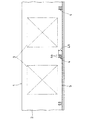
前記段ボールシート1は、図2に示すように、下面側の表ライナ紙2に予め印刷模様3がその走行方向に所定のピッチでプレプリントされ、さらに、この印刷模様3のピッチに合わせて所定の間隔で印刷された長さ切断位置の目安とされるピッチマーク4と、一方の幅縁部に沿って印刷された幅切り切断位置の目安とされるラインマーク5とが付与されたものである。ピッチマーク4は、ラインマーク5からシート内側へ所定の長さL0だけ幅方向に連続する2つ一組のマーク素子4aで形成されている。
As shown in FIG. 2, the
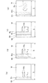
前記スリッタ6で幅切り切断された後の段ボールシート1は、図3(a)、(b)、(c)に示すように、幅切り切断位置によって、ラインマーク5の残存形態が異なる。図3(a)は、段ボールシート1がラインマーク5の内側で幅切り切断された場合、図3(b)は、ラインマーク5上で幅切り切断された場合、図3(c)は、ラインマーク5の外側で幅切り切断された場合である。通常は、図3(b)に示すように、ラインマーク5上で幅切り切断されることが多い。なお、図3(d)は、図3(b)のようにラインマーク5上で幅切り切断された場合について、印刷模様3がラインマーク5の近くまで張り出してプレプリントされている例を示す。プレプリントされる印刷模様3がラインマーク5と接する位置まで張り出すことはない。
As shown in FIGS. 3A, 3 </ b> B, and 3 </ b> C, the
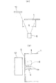
図4(a)、(b)に示すように、前記一次元CCDカメラ8は、走行する段ボールシート1の下面側に配置され、ピッチマーク4とラインマーク5が付与された段ボールシート1の下面側幅縁部と、その外側のシート外側部とを含めた幅方向の視野を連続的に撮影する。シート外側部の撮影視野には、段ボールシート1の幅縁部と間隔を開けて反射板12が配置されている。図4(b)は、代表例として、図3(b)の幅切り切断位置の段ボールシート1に対する一次元CCDカメラ8の撮影視野Sを示す。
As shown in FIGS. 4A and 4B, the one-
前記反射板12をシート外側部の撮影視野に段ボールシート1の幅縁部と間隔を開けて配置したのは、後述する一次元CCDカメラ8の検出出力の2値化画像処理で反射板12の撮影部分は確実に明部となるので、図3(a)、(b)に示したような場合であっても、一次元の画像処理の起点となる撮影視野の一方の端部に明部を常に存在させて、この明部の内側でピッチマーク4の検出起点となる暗部が走行方向に連続する幅方向部位を判別しやすくするためである。
The reason why the
前記コントローラ11は、刻々入力される一次元CCDカメラ8の各幅方向部位での検出出力を、明部と暗部に2値化する画像処理を行う。図5(a)、(b)、(c)、(d)は、それぞれ図3(a)、(b)、(c)、(d)に示した各幅切り切断位置の段ボールシート1に対する画像処理画面の例を示す。いずれの画像処理画面も横軸が一次元CCDカメラ8の撮影視野S、縦軸が段ボールシート1の走行方向に相当する時間軸であり、明部Wと暗部Bに2値化されている。
The
前記画像処理画面は、いずれも左端部に反射板12を撮影した明部W1が存在する。段ボールシート1がラインマーク5の内側で幅切り切断された場合を示す図5(a)の画像処理画面は、明部W1の右側にシート外側部を撮影した暗部B1が段ボールシート1の走行方向へ連続して存在し、この暗部B1のシート内側へ2つ一組のマーク素子4aを撮影した2本の暗部B3が幅方向に長さLだけ連続している。また、ラインマーク5上で幅切り切断された場合を示す図5(b)の画像処理画面は、明部W1の右側にシート外側部を撮影した暗部B1と、ラインマーク5を撮影した暗部B2とが合体した暗部B12が走行方向へ連続して存在し、この暗部B12のシート内側へ2本の暗部B3が幅方向に長さLだけ連続している。ラインマーク5の外側で幅切り切断された場合を示す図5(c)の画像処理画面は、明部W1の右側にシート外側部を撮影した暗部B1、段ボールシート1の無地の余裕代部を撮影した明部W2、ラインマーク5を撮影した暗部B2が順に走行方向へ連続して存在し、最もシート内方側の暗部B2のシート内側へ2本の暗部B3が幅方向に長さLだけ連続している。なお、図5(a)、(b)の場合は、いずれも走行方向へ連続する暗部B1、B12が幅方向の1箇所にしか存在しないので、これらがそれぞれ最もシート内方側の暗部B1、B12となる。
Each of the image processing screens has a bright portion W 1 obtained by photographing the reflecting
前記印刷模様3がラインマーク5の近くまで張り出してプレプリントされている例を示す図5(d)の画像処理画面は、図5(b)の画像処理画面と同様に、明部W1の右側にシート外側部を撮影した暗部B1と、ラインマーク5を撮影した暗部B2とが合体した暗部B12が走行方向へ連続して存在し、印刷模様3を撮影した暗部B4は、暗部B12と幅方向に連続せずに離れて存在する。したがって、この暗部B4はピッチマーク4の付与位置ではないと判別される。
The image processing screen of the printed pattern 3 in FIG. 5 showing an example that is preprinted overhanging close to the line marked 5 (d), similarly to the image processing screen of FIG. 5 (b), the bright portion W 1 the dark portion B 1 obtained by photographing the seat outer portion to the right, dark part B 4 in which the dark part B 2 taken
前記コントローラ11は、図5(a)、(b)、(c)に示したように、走行方向へ連続する最もシート内方側の暗部B1、B12、B2のシート内側へ2本の暗部B3が連続するときに、これらの各暗部B3の幅方向に連続する長さLが所定の数値範囲LL〜LU内であるか否かを判定し、数値範囲LL〜LU内であるときに、暗部B3が存在する走行方向位置をピッチマーク4の付与位置として識別する。この実施形態では、ピッチマーク4の各マーク素子4aの長さL0をパラメータとして、LL=0.5L0、LU=L0とされている。なお、段ボールシート1がラインマーク5の内側で幅切り切断されることが皆無の場合は、LL=LU=L0として数値範囲LL〜LUを所定の数値に限定してもよい。
As shown in FIGS. 5 (a), 5 (b) and 5 (c), the
上述した実施形態では、走行シートである段ボールシートのピッチマークを2つ一組のマーク素子で形成したものとしたが、ピッチマークのマーク素子の数は1つまたは3つ以上のものであってもよい。ただし、実施形態のもののように、ピッチマークのマーク素子の数を複数にすれば、走行方向へ連続する暗部のシート内側へ連続する暗部の本数によるチェックも加えて、より確実にピッチマークの付与位置を識別することができる。 In the embodiment described above, the pitch mark of the corrugated cardboard sheet, which is a traveling sheet, is formed by a set of two mark elements. However, the number of mark elements of the pitch mark is one or more than three. Also good. However, if the number of mark elements of the pitch mark is made plural as in the embodiment, a check is also made more reliably by adding a check based on the number of dark parts continuous to the inside of the sheet of dark parts continuous in the running direction. The position can be identified.
また、本発明に係る走行シートの切断位置検出装置は、走行シートがピッチマークとラインマークを付与されたものであればよく、段ボールシート以外の走行シートにも適用することができる。 The traveling sheet cutting position detecting device according to the present invention may be applied to traveling sheets other than the corrugated cardboard sheet as long as the traveling sheet is provided with a pitch mark and a line mark.
1 段ボールシート
2 表ライナ紙
3 印刷模様
4 ピッチマーク
4a マーク素子
5 ラインマーク
6 スリッタ
7 ロータリカッタ
8 一次元CCDカメラ
9 コンベア
10 回転計
11 コントローラ
12 反射板
DESCRIPTION OF
Claims (2)
Priority Applications (1)
| Application Number | Priority Date | Filing Date | Title |
|---|---|---|---|
| JP2004114394A JP2005297101A (en) | 2004-04-08 | 2004-04-08 | Cutting position detecting device of traveling sheet |
Applications Claiming Priority (1)
| Application Number | Priority Date | Filing Date | Title |
|---|---|---|---|
| JP2004114394A JP2005297101A (en) | 2004-04-08 | 2004-04-08 | Cutting position detecting device of traveling sheet |
Publications (1)
| Publication Number | Publication Date |
|---|---|
| JP2005297101A true JP2005297101A (en) | 2005-10-27 |
Family
ID=35329269
Family Applications (1)
| Application Number | Title | Priority Date | Filing Date |
|---|---|---|---|
| JP2004114394A Pending JP2005297101A (en) | 2004-04-08 | 2004-04-08 | Cutting position detecting device of traveling sheet |
Country Status (1)
| Country | Link |
|---|---|
| JP (1) | JP2005297101A (en) |
Cited By (5)
| Publication number | Priority date | Publication date | Assignee | Title |
|---|---|---|---|---|
| JP2007301662A (en) * | 2006-05-10 | 2007-11-22 | Rengo Co Ltd | Traveling sheet cutting position detection device |
| JP2007301670A (en) * | 2006-05-11 | 2007-11-22 | Rengo Co Ltd | Traveling sheet cutting position detection device |
| JP2010228021A (en) * | 2009-03-26 | 2010-10-14 | Asano Laboratories Co Ltd | Punching device and punching method |
| KR101879378B1 (en) * | 2016-03-30 | 2018-07-18 | 동우 화인켐 주식회사 | System and method for cutting of film |
| KR20210009356A (en) | 2018-08-29 | 2021-01-26 | 미츠비시 쥬고 기카이 시스템 가부시키가이샤 | Device and method for removing sheet defects and device for manufacturing corrugated sheet |
Citations (3)
| Publication number | Priority date | Publication date | Assignee | Title |
|---|---|---|---|---|
| JPH0246834U (en) * | 1988-09-22 | 1990-03-30 | ||
| JP2001246618A (en) * | 2000-03-07 | 2001-09-11 | Uht Corp | Upper lighting device in cutting device |
| JP2002273800A (en) * | 2001-03-15 | 2002-09-25 | Rengo Co Ltd | Device for controlling cutting position of traveling sheet |
-
2004
- 2004-04-08 JP JP2004114394A patent/JP2005297101A/en active Pending
Patent Citations (3)
| Publication number | Priority date | Publication date | Assignee | Title |
|---|---|---|---|---|
| JPH0246834U (en) * | 1988-09-22 | 1990-03-30 | ||
| JP2001246618A (en) * | 2000-03-07 | 2001-09-11 | Uht Corp | Upper lighting device in cutting device |
| JP2002273800A (en) * | 2001-03-15 | 2002-09-25 | Rengo Co Ltd | Device for controlling cutting position of traveling sheet |
Cited By (5)
| Publication number | Priority date | Publication date | Assignee | Title |
|---|---|---|---|---|
| JP2007301662A (en) * | 2006-05-10 | 2007-11-22 | Rengo Co Ltd | Traveling sheet cutting position detection device |
| JP2007301670A (en) * | 2006-05-11 | 2007-11-22 | Rengo Co Ltd | Traveling sheet cutting position detection device |
| JP2010228021A (en) * | 2009-03-26 | 2010-10-14 | Asano Laboratories Co Ltd | Punching device and punching method |
| KR101879378B1 (en) * | 2016-03-30 | 2018-07-18 | 동우 화인켐 주식회사 | System and method for cutting of film |
| KR20210009356A (en) | 2018-08-29 | 2021-01-26 | 미츠비시 쥬고 기카이 시스템 가부시키가이샤 | Device and method for removing sheet defects and device for manufacturing corrugated sheet |
Similar Documents
| Publication | Publication Date | Title |
|---|---|---|
| US6520080B1 (en) | System and method for utilizing web from a roll having splices | |
| JP3560922B2 (en) | Traveling sheet cutting position control device | |
| JP2009226716A (en) | Image forming apparatus, cutting device, image forming system image forming program and cutting program | |
| US20030033918A1 (en) | Device for trimming and automatic cutting of images on paper and other graphic and photographic substrates, in particular of large size | |
| JP2005297101A (en) | Cutting position detecting device of traveling sheet | |
| AU2008234396B2 (en) | Device and method for counting and detecting flat products | |
| US6499403B1 (en) | Method of detecting the positional accuracy of register and folding or cutting edges on flat copies | |
| EP0186619B1 (en) | Apparatus for detecting a gap in the junction area on a folded box | |
| JP2007245257A (en) | Cutting position detection device of traveling sheet | |
| EP0186750A2 (en) | Obstructed-field-indicia-sensing device | |
| AU596342B2 (en) | Scannable document velocity detector | |
| JP2017065855A (en) | Folding inspection equipment | |
| JP4746478B2 (en) | Method for detecting cutting position of traveling sheet | |
| US8489012B2 (en) | Paper handler | |
| JP2007301670A (en) | Traveling sheet cutting position detection device | |
| TWI386031B (en) | Image reading device with paging function | |
| CN109195806A (en) | Automatic method and apparatus for cutting substrates with printed images | |
| JP3659813B2 (en) | Mark identification method and apparatus | |
| JP4638791B2 (en) | Sheet position detecting device and image forming apparatus | |
| JP2009122973A (en) | Traveling web position control apparatus and method | |
| EA001531B1 (en) | Device and method for checking patternsdisposed on a material strip | |
| JPH06305218A (en) | Linkage control method for electrophotographic apparatus | |
| US7991307B2 (en) | Media elevator's current position identification method and a media handling device arranged with the same | |
| JP2004309409A (en) | Position inspection device for nesting line of cardboard sheet | |
| JP6504451B2 (en) | Inspection method, bookbinding method, inspection apparatus and bookbinding apparatus |
Legal Events
| Date | Code | Title | Description |
|---|---|---|---|
| A621 | Written request for application examination |
Effective date: 20070405 Free format text: JAPANESE INTERMEDIATE CODE: A621 |
|
| A977 | Report on retrieval |
Free format text: JAPANESE INTERMEDIATE CODE: A971007 Effective date: 20100218 |
|
| A131 | Notification of reasons for refusal |
Effective date: 20100601 Free format text: JAPANESE INTERMEDIATE CODE: A131 |
|
| A02 | Decision of refusal |
Free format text: JAPANESE INTERMEDIATE CODE: A02 Effective date: 20101012 |