JP2005297091A - Rubber bale transfer equipment and transfer method - Google Patents
Rubber bale transfer equipment and transfer method Download PDFInfo
- Publication number
- JP2005297091A JP2005297091A JP2004113242A JP2004113242A JP2005297091A JP 2005297091 A JP2005297091 A JP 2005297091A JP 2004113242 A JP2004113242 A JP 2004113242A JP 2004113242 A JP2004113242 A JP 2004113242A JP 2005297091 A JP2005297091 A JP 2005297091A
- Authority
- JP
- Japan
- Prior art keywords
- rubber
- jig
- place
- rubber bale
- bale
- Prior art date
- Legal status (The legal status is an assumption and is not a legal conclusion. Google has not performed a legal analysis and makes no representation as to the accuracy of the status listed.)
- Pending
Links
Images

Landscapes
- Manipulator (AREA)
Abstract
【課題】 充分な保持力を有すると共に、ゴムベールの積み重ね位置精度も要求されないようなゴムベール移送設備を提供すること。
【解決手段】第1の場所P1に置かれているゴムベールGを第2の場所P2へと移送するためのゴムベール移送設備であって、ゴムベールGを保持する2本のドリル7と、このドリル7をゴムベールG内にねじ込むための第1駆動機構と、この第1駆動機構を保持する治具保持部9と、この治具保持部9を第1の場所P1から第2の場所P2へと移送させる移送機構とを備え、第1の場所P1において、ドリル7を第1の方向に回転駆動することでゴムベールGの保持を行い、第2の場所P2において、ドリル7を第2の方向に回転駆動することでゴムベールGの保持を解除する。
【選択図】図3PROBLEM TO BE SOLVED: To provide a rubber bale transfer facility which has a sufficient holding force and does not require accuracy of stacking positions of rubber bales.
A rubber bale transfer facility for transferring a rubber bale G placed at a first place P1 to a second place P2, two drills 7 holding the rubber bale G, and the drill 7 A first driving mechanism for screwing the rubber into the rubber veil G, a jig holding part 9 for holding the first driving mechanism, and transferring the jig holding part 9 from the first place P1 to the second place P2. A transfer mechanism for holding the rubber bale G by rotating the drill 7 in the first direction at the first place P1, and rotating the drill 7 in the second direction at the second place P2. By driving, the holding of the rubber bale G is released.
[Selection] Figure 3
Description
本発明は、第1の場所に置かれているゴムベールを第2の場所へと移送するためのゴムベール移送設備及び移送方法に関するものである。 The present invention relates to a rubber bale transfer facility and a transfer method for transferring a rubber bale placed at a first place to a second place.
ゴムベールとは、直方体に成型された塊状のゴムであり、その処理工程において第1の場所から第2の場所へと移送される。ゴムベールは、そのいくつかがパレット上に積まれており、その積み重ねられたゴムベールを1つずつ取り出して第2の場所へと場所を移動させる。第2の場所に移動されたゴムベールは、その後の工程において粉砕処理され、最終的には電気部品や自動車部品等の製造に使用される。 The rubber veil is a lump of rubber molded into a rectangular parallelepiped, and is transferred from the first place to the second place in the processing step. Some of the rubber veils are stacked on a pallet, and the stacked rubber veils are taken out one by one and moved to a second location. The rubber bale moved to the second place is pulverized in a subsequent process, and finally used for manufacturing electrical parts, automobile parts, and the like.
ここで、ゴムベールを移動させる手段としていくつかの手段が知られている。1つ目はエアーバキューム方式である。このエアーバキューム方式は、吸着パッドを用いて人手により移送させる方法である。しかし、ゴムベールは1つの重さが30kgもあるため、人手で移送させるのはかなりの労力を有する。また、ゴムベールの表面形状が湾曲していたり、ゴムベールのラッピングが破れていたりすると、吸着パッドでうまく吸着できないという問題が生じる。 Here, several means are known as means for moving the rubber veil. The first is an air vacuum system. This air vacuum method is a method of manually transporting using a suction pad. However, a rubber bale weighs as much as 30 kg, so it is quite labor intensive to transport it manually. Further, if the surface shape of the rubber veil is curved or the rubber veil wrapping is broken, there arises a problem that it cannot be adsorbed well by the adsorption pad.
2つ目としてクランプ(チャック方式)がある。例えば、下記特許文献1に開示される天然ゴム塊の把持整列装置では、開閉アームの先端内側の相対抗する位置に天然ゴム塊を着脱可能に把持する係止爪を設けており、この係止爪により天然ゴム塊を把持して移送する。かかる把持機構の場合、パレットの上に積み重ねるゴムベールの位置決め精度が要求されるという問題があり、人手で行っているゴムベールの積み重ね作業に神経を使わなければならない。また、下記特許文献2では、ゴムベールを四方からクランプするクランプ板を備えたクランプハンドを開示する。やはりこの場合もゴムベールの位置決め精度が要求される。
The second is a clamp (chuck system). For example, in the natural rubber lump gripping and aligning device disclosed in
その他の手法として、爪や針状の治具をゴムベールに突き刺して移送する手法も考えられるが、把持強度の面で問題があり、移送途中で脱落してしまう可能性がある。従って、確実性、信頼性に欠ける手法である。
本発明は上記実情に鑑みてなされたものであり、その課題は、充分な保持力を有すると共に、ゴムベールの積み重ね位置精度も要求されないようなゴムベール移送設備及び移送方法を提供することである。 The present invention has been made in view of the above circumstances, and an object thereof is to provide a rubber bale transfer facility and a transfer method that have a sufficient holding force and that do not require accuracy in stacking positions of rubber bales.
上記課題を解決するため本発明に係るゴムベール移送設備は、
第1の場所に置かれているゴムベールを第2の場所へと移送するためのゴムベール移送設備であって、
ゴムベールを保持する螺旋状治具と、
この螺旋状治具をゴムベール内にねじ込むための第1駆動機構と、
この第1駆動機構を保持する治具保持部と、
この治具保持部を第1の場所から第2の場所へと移送させる移送機構とを備え、
第1の場所において、螺旋状治具を第1の方向に回転駆動することでゴムベールの保持を行い、第2の場所において、螺旋状治具を第2の方向に回転駆動することでゴムベールの保持を解除するように構成したことを特徴とするものである。
In order to solve the above problems, the rubber bale transfer facility according to the present invention is:
A rubber bale transfer facility for transferring a rubber bale placed at a first location to a second location,
A spiral jig for holding a rubber bale;
A first drive mechanism for screwing the helical jig into the rubber veil;
A jig holding portion for holding the first drive mechanism;
A transfer mechanism for transferring the jig holder from the first location to the second location,
At the first place, the rubber veil is held by rotating the spiral jig in the first direction, and at the second place, the rubber veil is rotated by driving the spiral jig in the second direction. It is characterized in that the holding is released.
かかるゴムベール移送設備による作用・効果は、次の通りである。ゴムベールを保持する保持手段として、螺旋状治具を使用する。この螺旋状治具をゴムベール内にねじ込むことでゴムベールを保持することができる。螺旋状治具の螺旋部分により確実にゴムベールを保持することができ、容易に脱落することがない。また、保持するときは、螺旋状治具を第1の方向に回転すれば、ゴムベール内部にねじ込まれていく。螺旋状治具をはずす時は、第1の方向とは逆の第2の方向に回転すれば、保持状態を解除することができる。さらに、螺旋状治具をねじ込む場合は、ゴムベールの表面であれば特に厳しい位置精度が要求されることはない。その結果、充分な保持力を有すると共に、ゴムベールの積み重ね位置精度も要求されないようなゴムベール移送設備を提供することができる。 The operations and effects of the rubber bale transfer facility are as follows. A spiral jig is used as a holding means for holding the rubber bale. The rubber veil can be held by screwing the spiral jig into the rubber veil. The rubber veil can be securely held by the spiral portion of the spiral jig and does not easily fall off. When holding, if the spiral jig is rotated in the first direction, it is screwed into the rubber bale. When removing the spiral jig, the holding state can be released by rotating in the second direction opposite to the first direction. Furthermore, when screwing the spiral jig, a particularly severe positional accuracy is not required as long as the surface is a rubber bale. As a result, it is possible to provide a rubber bale transfer facility that has a sufficient holding force and does not require accuracy in the stacking position of the rubber bales.
本発明に係る螺旋状治具は、少なくとも2本設けられており、直方体形状を有するゴムベールの長辺方向に沿って配置されるように、前記治具保持部を所定の軸芯周りに旋回させるための第2駆動機構が設けられていることが好ましい。 At least two spiral jigs according to the present invention are provided, and the jig holding portion is swung around a predetermined axis so as to be arranged along the long side direction of the rubber veil having a rectangular parallelepiped shape. It is preferable that a second drive mechanism is provided.
この構成によると、少なくとも2本の螺旋状治具が設けられており、この2本がゴムベールの長辺方向に配置された状態で、ゴムベールを保持することができる。保持しようとするゴムベールの長辺方向に沿って2本の螺旋状治具が配置されていない状態の時には、治具保持部を旋回させることで、長辺方向に螺旋状治具の配置を沿わせることができる。これにより、安定した状態でゴムベールを保持することができる。 According to this configuration, at least two spiral jigs are provided, and the rubber veil can be held in a state where the two are arranged in the long side direction of the rubber veil. When the two helical jigs are not arranged along the long side direction of the rubber veil to be held, the arrangement of the helical jigs is arranged in the long side direction by turning the jig holding part. Can be made. Thereby, a rubber bale can be held in a stable state.
本発明に係る螺旋状治具はドリルであることが好ましい。ドリルを用いることで、ゴムベールへのねじ込みを容易に行うことができる。 The helical jig according to the present invention is preferably a drill. By using a drill, screwing into the rubber bale can be easily performed.
本発明に係る螺旋状治具の表面には、耐摩耗性を有する表面処理が施されていることが好ましい。かかる表面処理を施すことで、長期間にわたってドリルを使用することができる。 The surface of the spiral jig according to the present invention is preferably subjected to a wear-resistant surface treatment. By applying such a surface treatment, a drill can be used over a long period of time.
本発明に係る前記移送機構は、
治具保持部を上下方向に駆動する第3駆動機構と、
治具保持部を水平第1方向に駆動する第4駆動機構と、
治具保持部を水平第1方向と直交する水平第2方向に駆動する第5駆動機構とを備えていることが好ましい。
The transfer mechanism according to the present invention includes:
A third drive mechanism for driving the jig holding portion in the vertical direction;
A fourth drive mechanism for driving the jig holding portion in the first horizontal direction;
It is preferable to include a fifth drive mechanism that drives the jig holding portion in a second horizontal direction orthogonal to the first horizontal direction.
この構成によると、治具保持部、すなわち、 螺旋状治具を3次元空間内で任意に移動させることができる。 According to this configuration, the jig holding portion, that is, the spiral jig can be arbitrarily moved in the three-dimensional space.
本発明において、ゴムベールは所定個数がパレットに搭載されており、第1の場所においてすべてのゴムベールが取り出された空のパレットをパレット回収位置に移送するためのパレット移送機構が設けられていることが好ましい。 In the present invention, a predetermined number of rubber balers are mounted on the pallet, and a pallet transfer mechanism is provided for transferring an empty pallet from which all the rubber balers have been taken out to the pallet collection position in the first place. preferable.
かかるパレット移送機構を設けることでパレットを確実に回収でき、次のパレットに搭載されているゴムベールの移送を引き続き行うことができる。 By providing such a pallet transfer mechanism, the pallet can be reliably recovered, and the rubber veil mounted on the next pallet can be continuously transferred.
上記課題を解決するため本発明に係るゴムベール移送方法は、
第1の場所に置かれているゴムベールを第2の場所へと移送するためのゴムベール移送方法であって、
第1の場所において、螺旋状治具を第1の方向に回転してゴムベール内にねじ込む工程と、
この治具保持部により保持されたゴムベールを第1の場所から第2の場所へと移送させる工程と、
第2の場所において、螺旋状治具を第1の方向とは逆の第2の方向に回転駆動することでゴムベールの保持を解除する工程とを有することを特徴とするものである。
In order to solve the above problems, the rubber bale transfer method according to the present invention is:
A rubber bale transfer method for transferring a rubber bale placed in a first place to a second place,
In a first location, rotating a helical jig in a first direction and screwing it into a rubber veil;
Transferring the rubber veil held by the jig holding portion from the first place to the second place;
And a step of releasing the holding of the rubber bale by rotationally driving the spiral jig in a second direction opposite to the first direction at the second location.
かかる構成による作用・効果は、既に述べた通りである。 The operations and effects of this configuration are as described above.
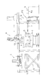
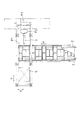
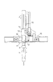
本発明に係るゴムベール移送設備の好適な実施形態を図面を用いて説明する。図1は、ゴムベール移送設備の構成を示す正面図、図2は、ゴムベール移送設備の構成を示す平面図、図3は、ゴムベール移送設備の構成を示す要部正面図、図4は、同じく要部側面図である。 A preferred embodiment of a rubber bale transfer facility according to the present invention will be described with reference to the drawings. 1 is a front view showing the configuration of the rubber bale transfer facility, FIG. 2 is a plan view showing the configuration of the rubber bale transfer facility, FIG. 3 is a front view of the main part showing the configuration of the rubber bale transfer facility, and FIG. FIG.
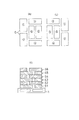
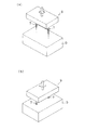
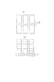
移送対象となるゴムベールGは、直方体形状を有しており、図5のような形態(以下、「石垣積み」と称する)で積まれている。ゴムベールGは前工程において直方体の形状に成型されたものが、運び込まれており、石垣積みされている。1段あたり6個のゴムベールGが図5に図示するような配置規則に基づいて、6段積みされている。なお、ゴムベールGの配置は、図5(a)(b)の2通りがある。図5(c)のS2,S4,S6は(a)の配置であり、S1,S3,S5は(b)の配置となっており、交互に異なる配置を繰り返している。なお、この6個×6段のゴムベールGを1組として1つのパレット1の上に搭載されている。
The rubber veil G to be transferred has a rectangular parallelepiped shape and is stacked in a form as shown in FIG. 5 (hereinafter referred to as “stone wall pile”). The rubber veil G, which has been formed into a rectangular parallelepiped shape in the previous process, is brought in and piled up with stone walls. Six rubber bales G per stage are stacked on the basis of the arrangement rule as shown in FIG. Note that there are two arrangements of the rubber veil G as shown in FIGS. In FIG. 5C, S2, S4, and S6 are the arrangement of (a), and S1, S3, and S5 are the arrangement of (b), and different arrangements are repeated alternately. The 6 pieces × 6 stages of rubber bales G are mounted on one
なお、ゴムベールGの積み重ね方法としては、図8に示すような方法もある。図8に示す積み重ね方法のほうが図5よりもシンプルであるが、一番上のゴムベールGを引き上げようとする時、そのすぐ下にあるゴムベールGもいっしょにひきづられて上がろうとする傾向がある。これは上下のゴムベールGの裏面と表面がぴったりと密着しているためである。図5のような石垣積みの場合は、上下のゴムベールGが密着している表面積が小さくなるので、確実に1番上のゴムベールGのみを引き上げることができる。 As a method for stacking the rubber veils G, there is also a method as shown in FIG. The stacking method shown in FIG. 8 is simpler than that of FIG. 5, but when the upper rubber bale G is to be pulled up, the rubber bale G immediately below it tends to be pulled together. is there. This is because the back and front surfaces of the upper and lower rubber veils G are in close contact with each other. In the case of stone wall stacking as shown in FIG. 5, the surface area with which the upper and lower rubber veils G are in close contact with each other is reduced, so that only the uppermost rubber bleed G can be reliably pulled up.
図2に示すようにゴムベールGを搭載したパレット1は、図2の矢印A方向に移送される。図2では、5パレット分のゴムベールが図示されており、ローラコンベア2により移送される。図2において、パレット1の移送方向の最も下流側が第1の場所に相当し、第1の場所P1の右方向に第2の場所P2が設定されている。第2の場所P2に降ろされたゴムベールGは、プッシャー(押出機構)3により第3の場所P3の方向に押出される。このゴムベールGは、粉砕処理等の後工程へと更に移送されることになる。
As shown in FIG. 2, the
第1の場所P1にあるパレット1上のゴムベールGは、ゴムベール移送機構により1つずつ保持されて第2の場所P2へと移送されていき、すべてのゴムベールGが移送されると、空のパレット1は、パレット移送機構4(図1参照)により回収される。パレット移送機構4は、吸着パッドによりパレット1を吸着して移送することができる。空のパレット1は、リフター5の上(パレット回収位置に相当)に積み重ねられる。
The rubber veils G on the
次にゴムベール移送機構6について、図3、図4により説明する。ゴムベールGを保持するための治具として、2本のドリル7(螺旋状治具に相当)が使用される。ドリル7を回転させてゴムベールG内にねじ込んでいくことにより、ゴムベールGを保持することができる。2本のドリル7は、ねじ込み用のギヤードモータ8(第1駆動機構に相当)により回転駆動される。ギヤードモータ8とドリル7とは、ベルトにより連結される。ギヤードモータ8とドリル7は、治具保持部9に取り付けられ、保持されている。
Next, the rubber
治具保持部9は、旋回用ギヤードモータ10により方向を90゜変換できるようにしている。図5の石垣積みで説明したように、ゴムベールGの配置方向は長手方向がY方向(水平第2方向・・・図2参照)に沿う方向と、長手方向がX方向(水平第1方向)の2通りが存在する。そこで、2本のドリル7でゴムベールGを保持する場合は、2本のドリル7が長手方向に配列した状態で保持できるように旋回可能な機構(第2駆動機構に相当)が設けられている。ギヤードモータ10に連結されたギヤ11により、治具保持部9が回転軸9a回りに旋回駆動される。旋回前と旋回後の状態が図6に示される。旋回用のギヤードモータ10は、更に別の保持部12により取り付け保持されている。
The
保持部12を上下方向(Z方向)に駆動できるように昇降用サーボモータ14が設けられている。サーボモータ14と、ラック&ピニオン機構15により、保持部12、すなわち、2本のドリル7に把持されたゴムベールGが上下方向に駆動される。サーボモータ14は、フレーム13の上下部分13aに取り付けられている。サーボモータ14とラック&ピニオン15は、第3駆動機構に相当する。
A lifting
フレーム13の水平部分13bは、別の水平本体部16に沿って(Y方向に相当)移動できるように構成される。水平部分13bには、Y軸走行用サーボモータ17が取り付けられており、ラック&ピニオン18によりフレーム13をY軸方向に移動させる。ラック&ピニオンのうち、ピニオンはサーボモータ17に連結され、ラックが水平本体部16に取り付けられる。サーボモータ17とラック&ピニオン18は、第4駆動機構に相当する。
The
水平本体部16をX軸方向に沿って移動させるためのX軸走行用サーボモータ19(第5駆動機構に相当)が設けられており、敷地内に設置された固定フレーム21に対して水平本体部16を移動させる。サーボモータ19の駆動力は、駆動伝達部20により伝達される。以上のような移送機構を設けることにより、パレット1の上にあるゴムベールGを保持して、第2の場所まで移送させることができる。図5に示すように、ゴムベールGは常に同じ場所に位置しているわけではないので、夫々の位置に対してドリル7を移動させる必要がある。本発明のように、水平面内のX,Y方向に移動させる機構を備えているので、どの位置にあるゴムベールGも確実に保持することができる。
An X-axis traveling servomotor 19 (corresponding to a fifth drive mechanism) for moving the horizontal
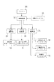
<制御ブロック図>
次に、ゴムベール移送設備の制御ブロック図を図7により説明する。制御装置30は、設備の各部の制御を行う中核部である。制御プログラム31に基づいて、各部の動作制御を行う。例えば、石垣積みされたゴムベールGを取り出していく順序は、予めプログラムされている。旋回用ギヤードモータ10は、旋回駆動部32(駆動回路)により駆動される。ねじ込み用ギヤードモータ8は、ドリル駆動部33により駆動される。昇降用サーボモータ14、X軸走行用サーボモータ19、Y軸走行用サーボモータ17は、XYZ駆動部34により駆動される。また、各駆動部に指令を与えるために必要に応じて各種センサー35が設けられる。例えば、ドリル7の先端がゴムベールGの表面に接触したことを検出するセンサー等が設けられる。また、ドリル7が現在どの位置(X,Y,Z座標)にあるのかを検出するセンサーを設けておくことが好ましい。
<Control block diagram>
Next, a control block diagram of the rubber bale transfer facility will be described with reference to FIG. The
<ゴムベールの取り出し動作>
次に、ゴムベールGを第1の場所から第2の場所へ移送する場合の動作を説明する。図2に示すように、ゴムベールGを搭載したペレット1が順番に移送されてくる。ペレット1に搭載されているゴムベールGの一番上の段の配置は、図5(a)に示すとおりであり、図示された順番にゴムベールGを取り出していく。まず1番目のゴムベールGを保持すべく、保持対象のゴムベールGの位置にドリル7が位置するように、X,Y座標の位置調整を行う。また、ゴムベールGの方向に応じて、旋回用ギヤードモータ10を駆動させる。ドリル7の位置設定が終了すると、ドリル7を回転させながら降下させていく。ドリル7の先端がゴムベールGの表面に接触してから、所定長さだけドリル7がねじ込まれる。
<Releasing operation of rubber bale>
Next, the operation when the rubber bale G is transferred from the first place to the second place will be described. As shown in FIG. 2, the
所定長さのドリル7のねじ込みが行われた後、ドリル7の回転駆動は停止する。その後、昇降用サーボモータ14を駆動させて、ゴムベールGを上昇させ、第1の場所P1から第2の場所P2へと移送する。この時の移動は、X・Y走行用サーボモータ17,19により行われる。第2の場所P2に移送された後、昇降用サーボモータ17によりゴムベールGを所定高さまで降下させ、ドリル7をねじ込む時とは逆回転させる。これにより、保持状態が解除され、ゴムベールGは第2の場所P2に設置される。
After the predetermined length of the
第2の場所P2に置かれたゴムベールGは、プッシャー3により第3の場所へと押し込まれる。この第3の場所において、粉砕処理が行われる。一方、ゴムベールGの保持を解除した後、ドリル7は第2の場所P2から第1の場所P1へと戻り、次のゴムベールGの保持を行う。以下、パレット1の上のゴムベールGがすべて第2の場所P2へ移送されるまで繰り返す。パレット1上のゴムベールGをすべて移送すると、空になったパレット1はパレット移送機構4により図1に示すようなリフター5の上に置かれる。空のパレット1が移送された後、次のパレット1を第1の場所P1に位置させるべく、ローラコンベア2を駆動する。以下、同じような動作を繰り返す。
The rubber bale G placed in the second place P2 is pushed into the third place by the
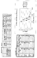
<実施例>
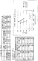
次に、実際に保持テストを行った。ゴムベールGの素材としてEPDMゴムを使用した。ねじ込み長さを50mmと100mmの2種類でテストした。螺旋状治具としてのドリルとしては、図示するように標準規格品、ねじ山を高くしたもの、ねじ山を低くしたものの3通りを使用した。ドリルの材質は、鉄製のものを使用した。ゴムベール1つの重さは28kgであり、この上に更に別のウェイト(5kg、10kg)を載せた状態のものと、ウェイトを載せない状態のものとでテストした。
<Example>
Next, a retention test was actually performed. EPDM rubber was used as a material for the rubber veil G. Two types of screwing lengths of 50 mm and 100 mm were tested. As the drill as the spiral jig, three types were used as shown in the figure: a standard product, one with a higher thread, and one with a lower thread. The drill material used was iron. The weight of one rubber bale was 28 kg, and it was tested with another weight (5 kg, 10 kg) placed thereon and with no weight placed thereon.
ねじ込み長さ50mmの場合のテスト結果は図9に、100mmの場合のテスト結果は図10に示される。これらの図から分かるように、ねじ込み長さ50mmの場合は、同じ外径とすれば、ねじ山の高いものほど保持時間が長くなる。ねじ込み長さが100mmとなると、標準品とねじ山を高くしたドリルとでは、大きな差は見られなかった。ドリルによりゴムベールGを第1の場所から第2の場所へと移送する時間は、数十秒程度であるから十分に実用に耐えうるレベルである。 FIG. 9 shows the test result when the screwing length is 50 mm, and FIG. 10 shows the test result when the screwing length is 100 mm. As can be seen from these figures, in the case of a screw-in length of 50 mm, if the same outer diameter is used, the higher the thread, the longer the holding time. When the screwing length was 100 mm, there was no significant difference between the standard product and the drill with a high thread. The time for transferring the rubber veil G from the first place to the second place by the drill is about several tens of seconds, so that it can be sufficiently practically used.
テストでは鉄製のドリルを使用したが、ねじ込み動作を繰り返しても、金属紛のゴムベールへの混入は確認されなかった。ただし、より安全性を高めるために、鋼製のドリルを使用したり、硬質Crメッキ(耐摩耗性を有する表面処理の一例)を施すことが好ましい。また、ねじ込み動作を10回繰り返したが、治具温度の上昇についてもほとんど見られなかった。実稼動状態では、5分に1度程度のねじ込み動作であるため、温度上昇の問題もほとんどない。 In the test, an iron drill was used, but even if the screwing operation was repeated, mixing of metal powder into the rubber veil was not confirmed. However, in order to further improve safety, it is preferable to use a steel drill or to apply hard Cr plating (an example of a surface treatment having wear resistance). Further, the screwing operation was repeated 10 times, but almost no increase in the jig temperature was observed. In the actual operation state, since the screwing operation is performed once every 5 minutes, there is almost no problem of temperature rise.
<別実施形態>
本実施形態で開示する機構は一例を示すものであり、これに限定されるものではない。例えば、螺旋状治具としては、ドリル以外のネジ形状を有するものを使用してもよい。また、螺旋状治具としてコイルバネ状の形状をした治具を使用してもよい。螺旋状治具の個数は2個ではなく、3個以上としてもよい。
<Another embodiment>
The mechanism disclosed in the present embodiment is an example, and the present invention is not limited to this. For example, as the spiral jig, one having a screw shape other than a drill may be used. Further, a jig having a coil spring shape may be used as the spiral jig. The number of spiral jigs is not two, but may be three or more.
2本ドリル(螺旋状治具)の回転方向であるが、次のような構成が考えられる。1つ目は、保持動作のときは2本とも右回転(第1の方向)、保持解除のときは2本とも左回転(第2の方向)とすることである。2つ目は、保持動作のときは2本とも左回転(第1の方向)、保持解除のときは2本とも右回転(第2の方向)とすることである。当然1つ目と2つ目の例では形成されるネジの方向は逆になる。3つ目は、保持動作のとき1本は右回転、1本は左回転とし(これらが第1の方向となる)、保持解除のときは1本は左回転、1本は右回転(これらが第2の方向となる)としてもよい。3本以上の時も同様に考えることができる。 The rotation direction of the two drills (spiral jig) is as follows. The first is that both are rotated to the right (first direction) during the holding operation and both are rotated to the left (second direction) when the holding is released. Secondly, both of the two are rotated left (first direction) during the holding operation, and both are rotated right (second direction) when the holding is released. Of course, in the first and second examples, the direction of the formed screw is reversed. Third, when holding, one is rotating right, and one is rotating left (they are in the first direction), when releasing, one is rotating left, and one is rotating right (these May be the second direction). The same applies when there are three or more.
XYZ方向に移送する機構をパレット側に設けてもよい。すなわち、 パレットがXYZ方向に移動できるような機構を採用してもよい。 A mechanism for transferring in the XYZ directions may be provided on the pallet side. That is, a mechanism that allows the pallet to move in the XYZ directions may be employed.
石垣積みの形態については図5のものに限定されるものではない。例えば、1段あたりの個数や何段にするかは、適宜変更可能である。また、図5ではゴムベールの配置パターンは2通りであるが、3通り以上としてもよい。 The form of stone wall stacking is not limited to that shown in FIG. For example, the number per stage and the number of stages can be appropriately changed. In FIG. 5, the arrangement pattern of the rubber veil is two, but it may be three or more.
1 パレット
2 ローラコンベア
3 プッシャー
4 パレット移送機構
5 リフター
6 ゴムベール移送機構
7 ドリル
8 ねじ込み用ギヤードモータ
9 治具保持部
10 旋回用ギヤードモータ
14 昇降用サーボモータ
15 ラック&ピニオン機構
17 Y軸走行用サーボモータ
18 ラック&ピニオン
19 X軸走行用サーボモータ
20 駆動伝達部
G ゴムベール
P1 第1の場所
P2 第2の場所
P3 第3の場所
DESCRIPTION OF
Claims (7)
ゴムベールを保持する螺旋状治具と、
この螺旋状治具をゴムベール内にねじ込むための第1駆動機構と、
この第1駆動機構を保持する治具保持部と、
この治具保持部を第1の場所から第2の場所へと移送させる移送機構とを備え、
第1の場所において、螺旋状治具を第1の方向に回転駆動することでゴムベールの保持を行い、第2の場所において、螺旋状治具を第2の方向に回転駆動することでゴムベールの保持を解除するように構成したことを特徴とするゴムベール移送設備。 A rubber bale transfer facility for transferring a rubber bale placed at a first location to a second location,
A spiral jig for holding a rubber bale;
A first drive mechanism for screwing the helical jig into the rubber veil;
A jig holding portion for holding the first drive mechanism;
A transfer mechanism for transferring the jig holder from the first location to the second location,
At the first place, the rubber veil is held by rotating the spiral jig in the first direction, and at the second place, the rubber veil is rotated by driving the spiral jig in the second direction. A rubber bale transfer facility characterized in that the holding is released.
治具保持部を上下方向に駆動する第3駆動機構と、
治具保持部を水平第1方向に駆動する第4駆動機構と、
治具保持部を水平第1方向と直交する水平第2方向に駆動する第5駆動機構とを備えていることを特徴とする請求項1〜4のいずれか1項に記載のゴムベール移送設備。 The transfer mechanism is
A third drive mechanism for driving the jig holding portion in the vertical direction;
A fourth drive mechanism for driving the jig holding portion in the first horizontal direction;
5. The rubber bale transfer facility according to claim 1, further comprising a fifth drive mechanism that drives the jig holding portion in a second horizontal direction orthogonal to the first horizontal direction.
第1の場所において、螺旋状治具を第1の方向に回転してゴムベール内にねじ込む工程と、
この治具保持部により保持されたゴムベールを第1の場所から第2の場所へと移送させる工程と、
第2の場所において、螺旋状治具を第1の方向とは逆の第2の方向に回転駆動することでゴムベールの保持を解除する工程とを有することを特徴とするゴムベール移送方法。 A rubber bale transfer method for transferring a rubber bale placed in a first place to a second place,
In a first location, rotating a helical jig in a first direction and screwing it into a rubber veil;
Transferring the rubber veil held by the jig holding portion from the first place to the second place;
And a step of releasing the holding of the rubber bale by rotationally driving the spiral jig in a second direction opposite to the first direction at the second location.
Priority Applications (1)
| Application Number | Priority Date | Filing Date | Title |
|---|---|---|---|
| JP2004113242A JP2005297091A (en) | 2004-04-07 | 2004-04-07 | Rubber bale transfer equipment and transfer method |
Applications Claiming Priority (1)
| Application Number | Priority Date | Filing Date | Title |
|---|---|---|---|
| JP2004113242A JP2005297091A (en) | 2004-04-07 | 2004-04-07 | Rubber bale transfer equipment and transfer method |
Publications (1)
| Publication Number | Publication Date |
|---|---|
| JP2005297091A true JP2005297091A (en) | 2005-10-27 |
Family
ID=35329261
Family Applications (1)
| Application Number | Title | Priority Date | Filing Date |
|---|---|---|---|
| JP2004113242A Pending JP2005297091A (en) | 2004-04-07 | 2004-04-07 | Rubber bale transfer equipment and transfer method |
Country Status (1)
| Country | Link |
|---|---|
| JP (1) | JP2005297091A (en) |
Cited By (11)
| Publication number | Priority date | Publication date | Assignee | Title |
|---|---|---|---|---|
| CN103084765A (en) * | 2013-02-04 | 2013-05-08 | 张家港市永发机器人科技有限公司 | Cantilever type slide rail mechanism applied to rectangular coordinate system robot welding |
| JP2013123788A (en) * | 2011-12-16 | 2013-06-24 | Honda Motor Co Ltd | Workpiece work system |
| EP2927175A1 (en) * | 2014-04-01 | 2015-10-07 | Suzuka Engineering Co., Ltd | Method for lifting and conveying bale rubber and device for the same |
| JP2018051656A (en) * | 2016-09-27 | 2018-04-05 | 日産自動車株式会社 | Transfer device and transfer method |
| CN109202874A (en) * | 2017-07-05 | 2019-01-15 | 海南大学 | A kind of rubber dryness production line unloads glue manipulator |
| WO2019193272A1 (en) | 2018-04-06 | 2019-10-10 | Compagnie Generale Des Etablissements Michelin | Device and method for gripping a flexible elastomer block |
| WO2022101571A1 (en) | 2020-11-16 | 2022-05-19 | Compagnie Generale Des Etablissements Michelin | Device and method for transferring elastomer blocks |
| CN114929438A (en) * | 2019-11-13 | 2022-08-19 | 开放思维风险投资个人有限公司 | System for picking up components |
| EP4046760A1 (en) | 2021-02-23 | 2022-08-24 | Compagnie Generale Des Etablissements Michelin | Robot equipped with a gripper for performing a picking process |
| US12304737B2 (en) | 2021-05-06 | 2025-05-20 | Compagnie Generale Des Etablissements Michelin | Automated flow control for rubber product manufacturing processes |
| US12378086B2 (en) | 2021-02-23 | 2025-08-05 | Compagnie Generale Des Etablissements Michelin | Automated cell for performing container control during a process of picking rubber blocks |
-
2004
- 2004-04-07 JP JP2004113242A patent/JP2005297091A/en active Pending
Cited By (19)
| Publication number | Priority date | Publication date | Assignee | Title |
|---|---|---|---|---|
| JP2013123788A (en) * | 2011-12-16 | 2013-06-24 | Honda Motor Co Ltd | Workpiece work system |
| CN103084765A (en) * | 2013-02-04 | 2013-05-08 | 张家港市永发机器人科技有限公司 | Cantilever type slide rail mechanism applied to rectangular coordinate system robot welding |
| EP2927175A1 (en) * | 2014-04-01 | 2015-10-07 | Suzuka Engineering Co., Ltd | Method for lifting and conveying bale rubber and device for the same |
| JP2015196580A (en) * | 2014-04-01 | 2015-11-09 | 鈴鹿エンヂニヤリング株式会社 | Hanging transport method of bale rubber and its device |
| US9394145B2 (en) | 2014-04-01 | 2016-07-19 | Suzuka Engineering Co., Ltd. | Method for lifting and conveying bale rubber and device for the same with grip safety mechanism |
| JP2018051656A (en) * | 2016-09-27 | 2018-04-05 | 日産自動車株式会社 | Transfer device and transfer method |
| CN109202874A (en) * | 2017-07-05 | 2019-01-15 | 海南大学 | A kind of rubber dryness production line unloads glue manipulator |
| FR3079767A1 (en) * | 2018-04-06 | 2019-10-11 | Compagnie Generale Des Etablissements Michelin | DEVICE AND METHOD FOR PRETENSION OF FLEXIBLE ELASTOMERIC BLOCK |
| WO2019193272A1 (en) | 2018-04-06 | 2019-10-10 | Compagnie Generale Des Etablissements Michelin | Device and method for gripping a flexible elastomer block |
| CN114929438A (en) * | 2019-11-13 | 2022-08-19 | 开放思维风险投资个人有限公司 | System for picking up components |
| JP2023501548A (en) * | 2019-11-13 | 2023-01-18 | オープン マインド ベンチャーズ エス.エル.ユー. | system for picking up elements |
| JP7690956B2 (en) | 2019-11-13 | 2025-06-11 | オープン マインド ベンチャーズ エス.エル.ユー. | Element Pick-up System |
| WO2022101571A1 (en) | 2020-11-16 | 2022-05-19 | Compagnie Generale Des Etablissements Michelin | Device and method for transferring elastomer blocks |
| FR3116223A1 (en) | 2020-11-16 | 2022-05-20 | Compagnie Generale Des Etablissements Michelin | Device and method for transferring elastomeric blocks |
| US12214976B2 (en) | 2020-11-16 | 2025-02-04 | Compagnie Generale Des Etablissements Michelin | Device and method for transferring elastomer blocks |
| EP4046760A1 (en) | 2021-02-23 | 2022-08-24 | Compagnie Generale Des Etablissements Michelin | Robot equipped with a gripper for performing a picking process |
| US11820609B2 (en) | 2021-02-23 | 2023-11-21 | Compagnie Generale Des Etablissements Michelin | Robot equipped with a gripper for performing a picking process |
| US12378086B2 (en) | 2021-02-23 | 2025-08-05 | Compagnie Generale Des Etablissements Michelin | Automated cell for performing container control during a process of picking rubber blocks |
| US12304737B2 (en) | 2021-05-06 | 2025-05-20 | Compagnie Generale Des Etablissements Michelin | Automated flow control for rubber product manufacturing processes |
Similar Documents
| Publication | Publication Date | Title |
|---|---|---|
| JP5423441B2 (en) | Work system, robot apparatus, and manufacturing method of machine product | |
| CN105345281B (en) | Laser welding machine | |
| EP2358617B2 (en) | Stacking apparatus and method of multi-layer stacking of objects on a support | |
| KR101488540B1 (en) | Article handling apparatus, system and method | |
| JP2005297091A (en) | Rubber bale transfer equipment and transfer method | |
| KR20210044846A (en) | Robot and robot system having the same | |
| DE102019115571B4 (en) | Fast removal of cut parts from a processing plant | |
| CN111993403A (en) | Control method of manipulator with material taking and stacking functions | |
| CN104624831B (en) | A kind of cold extrusion automatic assembly line | |
| CN108163531B (en) | Automatic feeding equipment | |
| CN101312805A (en) | machine tool | |
| KR101940184B1 (en) | Wafer transport method and device | |
| JP5429117B2 (en) | Hand and robot | |
| EP1893512B1 (en) | Automatic depalletizer | |
| CN115959352B (en) | Bag unpacking robot and working method | |
| KR101829938B1 (en) | auto drilling apparatus for window frame handle assembly | |
| CN105537626B (en) | A kind of tensile test bar mechanized production system and method | |
| DE102009011301B4 (en) | Method and gripper for handling a container by means of a manipulator | |
| CN106863501A (en) | A kind of wood composite pallet nailing robot | |
| WO2011158100A1 (en) | Upgraded prehensile device for robotized systems, in particular for palletizing products or packs of products | |
| CN107378437A (en) | A kind of cylindrical workpiece assembles device | |
| JP2004345755A (en) | Palletizer | |
| JP5970283B2 (en) | Method and apparatus for supplying plate material to plate material processing apparatus | |
| JP5617512B2 (en) | Hand and robot | |
| JP5604259B2 (en) | Bent pipe manufacturing equipment |
Legal Events
| Date | Code | Title | Description |
|---|---|---|---|
| A621 | Written request for application examination |
Free format text: JAPANESE INTERMEDIATE CODE: A621 Effective date: 20070221 |
|
| A977 | Report on retrieval |
Free format text: JAPANESE INTERMEDIATE CODE: A971007 Effective date: 20080826 |
|
| A131 | Notification of reasons for refusal |
Free format text: JAPANESE INTERMEDIATE CODE: A131 Effective date: 20080828 |
|
| A02 | Decision of refusal |
Free format text: JAPANESE INTERMEDIATE CODE: A02 Effective date: 20090107 |