KR20210044846A - Robot and robot system having the same - Google Patents
Robot and robot system having the same Download PDFInfo
- Publication number
- KR20210044846A KR20210044846A KR1020217007811A KR20217007811A KR20210044846A KR 20210044846 A KR20210044846 A KR 20210044846A KR 1020217007811 A KR1020217007811 A KR 1020217007811A KR 20217007811 A KR20217007811 A KR 20217007811A KR 20210044846 A KR20210044846 A KR 20210044846A
- Authority
- KR
- South Korea
- Prior art keywords
- robot
- conveyor
- base
- arm
- base end
- Prior art date
Links
- 238000003384 imaging method Methods 0.000 claims description 17
- 238000001179 sorption measurement Methods 0.000 claims description 14
- 238000000034 method Methods 0.000 claims 10
- 238000010586 diagram Methods 0.000 description 11
- 230000000694 effects Effects 0.000 description 11
- 238000011144 upstream manufacturing Methods 0.000 description 9
- 238000009434 installation Methods 0.000 description 8
- 230000008859 change Effects 0.000 description 3
- 238000000605 extraction Methods 0.000 description 3
- 230000004048 modification Effects 0.000 description 3
- 238000012986 modification Methods 0.000 description 3
- 206010028980 Neoplasm Diseases 0.000 description 2
- 201000011510 cancer Diseases 0.000 description 2
- 239000004973 liquid crystal related substance Substances 0.000 description 2
- 239000011159 matrix material Substances 0.000 description 2
- 229920000742 Cotton Polymers 0.000 description 1
- 238000010521 absorption reaction Methods 0.000 description 1
- 230000009471 action Effects 0.000 description 1
- 238000004458 analytical method Methods 0.000 description 1
- 238000001514 detection method Methods 0.000 description 1
- 238000006073 displacement reaction Methods 0.000 description 1
- 238000005401 electroluminescence Methods 0.000 description 1
- 235000013305 food Nutrition 0.000 description 1
- 230000006870 function Effects 0.000 description 1
- 230000007246 mechanism Effects 0.000 description 1
- 235000021485 packed food Nutrition 0.000 description 1
- 230000000717 retained effect Effects 0.000 description 1
- 239000011435 rock Substances 0.000 description 1
- 229910052709 silver Inorganic materials 0.000 description 1
- 239000004332 silver Substances 0.000 description 1
Images


Classifications
-
- B—PERFORMING OPERATIONS; TRANSPORTING
- B65—CONVEYING; PACKING; STORING; HANDLING THIN OR FILAMENTARY MATERIAL
- B65G—TRANSPORT OR STORAGE DEVICES, e.g. CONVEYORS FOR LOADING OR TIPPING, SHOP CONVEYOR SYSTEMS OR PNEUMATIC TUBE CONVEYORS
- B65G61/00—Use of pick-up or transfer devices or of manipulators for stacking or de-stacking articles not otherwise provided for
-
- B—PERFORMING OPERATIONS; TRANSPORTING
- B25—HAND TOOLS; PORTABLE POWER-DRIVEN TOOLS; MANIPULATORS
- B25J—MANIPULATORS; CHAMBERS PROVIDED WITH MANIPULATION DEVICES
- B25J15/00—Gripping heads and other end effectors
- B25J15/0014—Gripping heads and other end effectors having fork, comb or plate shaped means for engaging the lower surface on a object to be transported
-
- B—PERFORMING OPERATIONS; TRANSPORTING
- B25—HAND TOOLS; PORTABLE POWER-DRIVEN TOOLS; MANIPULATORS
- B25J—MANIPULATORS; CHAMBERS PROVIDED WITH MANIPULATION DEVICES
- B25J15/00—Gripping heads and other end effectors
- B25J15/06—Gripping heads and other end effectors with vacuum or magnetic holding means
- B25J15/0616—Gripping heads and other end effectors with vacuum or magnetic holding means with vacuum
-
- B—PERFORMING OPERATIONS; TRANSPORTING
- B25—HAND TOOLS; PORTABLE POWER-DRIVEN TOOLS; MANIPULATORS
- B25J—MANIPULATORS; CHAMBERS PROVIDED WITH MANIPULATION DEVICES
- B25J5/00—Manipulators mounted on wheels or on carriages
-
- B—PERFORMING OPERATIONS; TRANSPORTING
- B25—HAND TOOLS; PORTABLE POWER-DRIVEN TOOLS; MANIPULATORS
- B25J—MANIPULATORS; CHAMBERS PROVIDED WITH MANIPULATION DEVICES
- B25J5/00—Manipulators mounted on wheels or on carriages
- B25J5/007—Manipulators mounted on wheels or on carriages mounted on wheels
-
- B—PERFORMING OPERATIONS; TRANSPORTING
- B25—HAND TOOLS; PORTABLE POWER-DRIVEN TOOLS; MANIPULATORS
- B25J—MANIPULATORS; CHAMBERS PROVIDED WITH MANIPULATION DEVICES
- B25J9/00—Programme-controlled manipulators
- B25J9/003—Programme-controlled manipulators having parallel kinematics
- B25J9/0033—Programme-controlled manipulators having parallel kinematics with kinematics chains having a prismatic joint at the base
-
- B—PERFORMING OPERATIONS; TRANSPORTING
- B25—HAND TOOLS; PORTABLE POWER-DRIVEN TOOLS; MANIPULATORS
- B25J—MANIPULATORS; CHAMBERS PROVIDED WITH MANIPULATION DEVICES
- B25J9/00—Programme-controlled manipulators
- B25J9/0084—Programme-controlled manipulators comprising a plurality of manipulators
-
- B—PERFORMING OPERATIONS; TRANSPORTING
- B25—HAND TOOLS; PORTABLE POWER-DRIVEN TOOLS; MANIPULATORS
- B25J—MANIPULATORS; CHAMBERS PROVIDED WITH MANIPULATION DEVICES
- B25J9/00—Programme-controlled manipulators
- B25J9/06—Programme-controlled manipulators characterised by multi-articulated arms
-
- B—PERFORMING OPERATIONS; TRANSPORTING
- B25—HAND TOOLS; PORTABLE POWER-DRIVEN TOOLS; MANIPULATORS
- B25J—MANIPULATORS; CHAMBERS PROVIDED WITH MANIPULATION DEVICES
- B25J9/00—Programme-controlled manipulators
- B25J9/16—Programme controls
- B25J9/1679—Programme controls characterised by the tasks executed
- B25J9/1682—Dual arm manipulator; Coordination of several manipulators
-
- B—PERFORMING OPERATIONS; TRANSPORTING
- B25—HAND TOOLS; PORTABLE POWER-DRIVEN TOOLS; MANIPULATORS
- B25J—MANIPULATORS; CHAMBERS PROVIDED WITH MANIPULATION DEVICES
- B25J9/00—Programme-controlled manipulators
- B25J9/16—Programme controls
- B25J9/1679—Programme controls characterised by the tasks executed
- B25J9/1689—Teleoperation
-
- B—PERFORMING OPERATIONS; TRANSPORTING
- B65—CONVEYING; PACKING; STORING; HANDLING THIN OR FILAMENTARY MATERIAL
- B65G—TRANSPORT OR STORAGE DEVICES, e.g. CONVEYORS FOR LOADING OR TIPPING, SHOP CONVEYOR SYSTEMS OR PNEUMATIC TUBE CONVEYORS
- B65G41/00—Supporting frames or bases for conveyors as a whole, e.g. transportable conveyor frames
- B65G41/001—Supporting frames or bases for conveyors as a whole, e.g. transportable conveyor frames with the conveyor adjustably mounted on the supporting frame or base
- B65G41/005—Supporting frames or bases for conveyors as a whole, e.g. transportable conveyor frames with the conveyor adjustably mounted on the supporting frame or base mounted for both pivotal and linear movement
-
- B—PERFORMING OPERATIONS; TRANSPORTING
- B65—CONVEYING; PACKING; STORING; HANDLING THIN OR FILAMENTARY MATERIAL
- B65G—TRANSPORT OR STORAGE DEVICES, e.g. CONVEYORS FOR LOADING OR TIPPING, SHOP CONVEYOR SYSTEMS OR PNEUMATIC TUBE CONVEYORS
- B65G47/00—Article or material-handling devices associated with conveyors; Methods employing such devices
- B65G47/74—Feeding, transfer, or discharging devices of particular kinds or types
- B65G47/90—Devices for picking-up and depositing articles or materials
- B65G47/91—Devices for picking-up and depositing articles or materials incorporating pneumatic, e.g. suction, grippers
- B65G47/915—Devices for picking-up and depositing articles or materials incorporating pneumatic, e.g. suction, grippers provided with drive systems with rotary movements only
-
- B—PERFORMING OPERATIONS; TRANSPORTING
- B65—CONVEYING; PACKING; STORING; HANDLING THIN OR FILAMENTARY MATERIAL
- B65G—TRANSPORT OR STORAGE DEVICES, e.g. CONVEYORS FOR LOADING OR TIPPING, SHOP CONVEYOR SYSTEMS OR PNEUMATIC TUBE CONVEYORS
- B65G47/00—Article or material-handling devices associated with conveyors; Methods employing such devices
- B65G47/74—Feeding, transfer, or discharging devices of particular kinds or types
- B65G47/90—Devices for picking-up and depositing articles or materials
- B65G47/91—Devices for picking-up and depositing articles or materials incorporating pneumatic, e.g. suction, grippers
- B65G47/918—Devices for picking-up and depositing articles or materials incorporating pneumatic, e.g. suction, grippers with at least two picking-up heads
-
- B—PERFORMING OPERATIONS; TRANSPORTING
- B65—CONVEYING; PACKING; STORING; HANDLING THIN OR FILAMENTARY MATERIAL
- B65G—TRANSPORT OR STORAGE DEVICES, e.g. CONVEYORS FOR LOADING OR TIPPING, SHOP CONVEYOR SYSTEMS OR PNEUMATIC TUBE CONVEYORS
- B65G67/00—Loading or unloading vehicles
- B65G67/02—Loading or unloading land vehicles
- B65G67/04—Loading land vehicles
- B65G67/08—Loading land vehicles using endless conveyors
-
- G—PHYSICS
- G05—CONTROLLING; REGULATING
- G05B—CONTROL OR REGULATING SYSTEMS IN GENERAL; FUNCTIONAL ELEMENTS OF SUCH SYSTEMS; MONITORING OR TESTING ARRANGEMENTS FOR SUCH SYSTEMS OR ELEMENTS
- G05B19/00—Programme-control systems
- G05B19/02—Programme-control systems electric
- G05B19/418—Total factory control, i.e. centrally controlling a plurality of machines, e.g. direct or distributed numerical control [DNC], flexible manufacturing systems [FMS], integrated manufacturing systems [IMS] or computer integrated manufacturing [CIM]
- G05B19/41815—Total factory control, i.e. centrally controlling a plurality of machines, e.g. direct or distributed numerical control [DNC], flexible manufacturing systems [FMS], integrated manufacturing systems [IMS] or computer integrated manufacturing [CIM] characterised by the cooperation between machine tools, manipulators and conveyor or other workpiece supply system, workcell
- G05B19/4182—Total factory control, i.e. centrally controlling a plurality of machines, e.g. direct or distributed numerical control [DNC], flexible manufacturing systems [FMS], integrated manufacturing systems [IMS] or computer integrated manufacturing [CIM] characterised by the cooperation between machine tools, manipulators and conveyor or other workpiece supply system, workcell manipulators and conveyor only
-
- B—PERFORMING OPERATIONS; TRANSPORTING
- B65—CONVEYING; PACKING; STORING; HANDLING THIN OR FILAMENTARY MATERIAL
- B65G—TRANSPORT OR STORAGE DEVICES, e.g. CONVEYORS FOR LOADING OR TIPPING, SHOP CONVEYOR SYSTEMS OR PNEUMATIC TUBE CONVEYORS
- B65G2201/00—Indexing codes relating to handling devices, e.g. conveyors, characterised by the type of product or load being conveyed or handled
- B65G2201/02—Articles
-
- B—PERFORMING OPERATIONS; TRANSPORTING
- B65—CONVEYING; PACKING; STORING; HANDLING THIN OR FILAMENTARY MATERIAL
- B65G—TRANSPORT OR STORAGE DEVICES, e.g. CONVEYORS FOR LOADING OR TIPPING, SHOP CONVEYOR SYSTEMS OR PNEUMATIC TUBE CONVEYORS
- B65G2203/00—Indexing code relating to control or detection of the articles or the load carriers during conveying
- B65G2203/04—Detection means
- B65G2203/041—Camera
-
- G—PHYSICS
- G05—CONTROLLING; REGULATING
- G05B—CONTROL OR REGULATING SYSTEMS IN GENERAL; FUNCTIONAL ELEMENTS OF SUCH SYSTEMS; MONITORING OR TESTING ARRANGEMENTS FOR SUCH SYSTEMS OR ELEMENTS
- G05B2219/00—Program-control systems
- G05B2219/30—Nc systems
- G05B2219/39—Robotics, robotics to robotics hand
- G05B2219/39102—Manipulator cooperating with conveyor
-
- Y—GENERAL TAGGING OF NEW TECHNOLOGICAL DEVELOPMENTS; GENERAL TAGGING OF CROSS-SECTIONAL TECHNOLOGIES SPANNING OVER SEVERAL SECTIONS OF THE IPC; TECHNICAL SUBJECTS COVERED BY FORMER USPC CROSS-REFERENCE ART COLLECTIONS [XRACs] AND DIGESTS
- Y02—TECHNOLOGIES OR APPLICATIONS FOR MITIGATION OR ADAPTATION AGAINST CLIMATE CHANGE
- Y02P—CLIMATE CHANGE MITIGATION TECHNOLOGIES IN THE PRODUCTION OR PROCESSING OF GOODS
- Y02P90/00—Enabling technologies with a potential contribution to greenhouse gas [GHG] emissions mitigation
- Y02P90/02—Total factory control, e.g. smart factories, flexible manufacturing systems [FMS] or integrated manufacturing systems [IMS]
Landscapes
- Engineering & Computer Science (AREA)
- Mechanical Engineering (AREA)
- Robotics (AREA)
- Aviation & Aerospace Engineering (AREA)
- General Engineering & Computer Science (AREA)
- Manufacturing & Machinery (AREA)
- Quality & Reliability (AREA)
- Physics & Mathematics (AREA)
- General Physics & Mathematics (AREA)
- Automation & Control Theory (AREA)
- Manipulator (AREA)
Abstract
베이스와, 상기 베이스에 그 기단이 고정되는 제1 로봇과, 상기 베이스에 그 기단이 고정되는 제2 로봇을 구비하고, 상기 제1 로봇은 제1 로봇 암과, 상기 제1 로봇 암의 선단에 장착되는 제1 로봇 핸드를 구비하고, 상기 제2 로봇은 제2 로봇 암과, 상기 제2 로봇 암의 선단에 장착되는 제2 로봇 핸드를 구비하며, 상기 제1 로봇 핸드는 컨베이어를 포함하고, 상기 제2 로봇 핸드는 워크를 유지하는 유지부를 포함하고, 상기 제2 로봇은 상기 유지부에 유지된 워크를 상기 제1 로봇의 컨베이어 반송면에 올려 해방하는 것을 특징으로 한다.A base, a first robot whose base end is fixed to the base, and a second robot whose base end is fixed to the base, and the first robot comprises a first robot arm and a front end of the first robot arm. It has a first robot hand to be mounted, the second robot has a second robot arm and a second robot hand mounted on the tip of the second robot arm, the first robot hand comprises a conveyor, The second robot hand may include a holding unit for holding a work, and the second robot may release the work held by the holding unit on a conveyor conveyance surface of the first robot.

Description
본 발명은 로봇 및 이를 구비하는 로봇 시스템에 관한 것이다.The present invention relates to a robot and a robot system including the same.
종래부터, 이동 가능한 컨베이어와, 당해 컨베이어의 반송면에 워크(work)를 유지(保持)하여 재치(載置)하는 유지 기구를 구비하는 로봇이 알려져 있다. 이러한 로봇으로서, 예를 들어, 특허문헌 1의 하역 장치가 있다.Conventionally, a robot having a movable conveyor and a holding mechanism for holding and placing a work on the conveying surface of the conveyor has been known. As such a robot, there is a loading and unloading apparatus of Patent Document 1, for example.
특허문헌 1의 하역 장치는 이동 가능한 컨베이어 및 추출 암을 구비한다. 이동 가능한 컨베이어가 하물에 가까워지도록 전진하고, 추출 암의 선단에 설치된 파지부에 의해 하물이 파지된다. 추출 암은 하물을 이동 컨베이어 상에 올린 후, 하물 회피 자세로 이동한다. 나아가, 이동 가능한 컨베이어는, 반송대의 위치까지 하강하고, 그 반송면을 구성하는 벨트를 회전시킴으로써, 하물을 반송대에 투입한다.The loading and unloading device of Patent Document 1 includes a movable conveyor and an extraction arm. The movable conveyor advances so as to approach the load, and the load is gripped by a gripping portion provided at the tip of the extraction arm. The extraction arm lifts the load on the moving conveyor and then moves to the load avoidance posture. Furthermore, the movable conveyor descends to the position of the conveyance table, and by rotating the belt constituting the conveyance surface, the article is put into the conveyance table.
그런데, 특허문헌 1의 하역 장치는 반송대에 인접한 위치에서 지면에 고정할 필요가 있기 때문에, 설치 장소가 한정적이 되어버리는 문제가 있었다.By the way, since the loading and unloading apparatus of Patent Document 1 needs to be fixed to the ground at a position adjacent to the conveying platform, there is a problem that the installation place becomes limited.
따라서, 본 발명은, 설치 장소가 한정적이지 않고, 이동 가능한 컨베이어에 의해 워크를 반송하는 것이 가능한 로봇 및 이를 구비하는 로봇 시스템을 제공하는 것을 목적으로 한다.Accordingly, an object of the present invention is to provide a robot capable of transporting a work by a movable conveyor, and a robot system including the same, where the installation location is not limited.
상기 과제를 해결하기 위하여, 본 발명에 따른 로봇은, 베이스와, 상기 베이스에 그 기단이 고정되는 제1 로봇과, 상기 베이스에 그 기단이 고정되는 제2 로봇을 구비하고, 상기 제1 로봇은 제1 로봇 암과, 상기 제1 로봇 암의 선단에 장착되는 제1 로봇 핸드를 구비하고, 상기 제2 로봇은 제2 로봇 암과, 상기 제2 로봇 암의 선단에 장착되는 제2 로봇 핸드를 구비하며, 상기 제1 로봇 핸드는 컨베이어를 포함하고, 상기 제2 로봇 핸드는 워크를 유지하는 유지부를 포함하고, 상기 제2 로봇은 상기 유지부에 의해 유지된 워크를 상기 제1 로봇의 컨베이어의 반송면에 올려 해방하는 것을 특징으로 한다.In order to solve the above problems, the robot according to the present invention includes a base, a first robot whose base end is fixed to the base, and a second robot whose base end is fixed to the base, and the first robot A first robot arm and a first robot hand mounted on the tip of the first robot arm, and the second robot includes a second robot arm and a second robot hand mounted on the tip of the second robot arm. And the first robot hand includes a conveyor, the second robot hand includes a holding unit for holding a work, and the second robot transfers the work held by the holding unit to the conveyor of the first robot. It is characterized in that it is lifted on the conveying surface and released.
상기 구성에 의하면, 제1 로봇 암의 선단에 컨베이어가 장착되기 때문에, 제1 로봇 암의 선단이 이동 가능한 범위에서 컨베이어를 이동시킬 수 있다. 또한, 제2 로봇이 유지부로 유지한 워크를 제1 로봇의 컨베이어 반송면에 올리고 해방하는 것이 가능하다. 그 결과, 설치 장소가 한정적이지 않고, 이동 가능한 컨베이어에 의해 워크를 반송하는 것이 가능한 로봇을 제공하는 것이 가능하다.According to the above configuration, since the conveyor is mounted on the tip of the first robot arm, the conveyor can be moved within a range in which the tip of the first robot arm is movable. Further, it is possible to lift and release the work held by the second robot by the holding unit on the conveyor conveyance surface of the first robot. As a result, it is possible to provide a robot capable of transporting a work by a movable conveyor, where the installation location is not limited.
상기 베이스는, 베이스 본체와, 상기 베이스 본체에 설치되는 가동부를 구비하고, 상기 제1 로봇은, 그 기단이 상기 베이스 본체에 고정되고, 상기 제2 로봇은, 그 기단이 상기 가동부에 고정됨으로써, 상기 제1 로봇의 기단과 상기 제2 로봇의 기단을 잇는 길이 방향에 직교하는 폭 방향 및 상기 길이 방향 중 적어도 어느 일방으로 이동 가능하여도 좋다.The base includes a base body and a movable part installed in the base body, and the first robot has its base end fixed to the base body, and the second robot has its base end fixed to the movable part, It may be movable in at least one of a width direction orthogonal to a longitudinal direction connecting the base end of the first robot and the base end of the second robot and the longitudinal direction.
상기 구성에 의하면, 베이스 본체에 설치되는 가동부에 의해, 제2 로봇이 상기 폭 방향 및 상기 길이 방향 중 적어도 어느 일방으로 이동 가능하기 때문에, 반송 대상이 되는 워크가 제2 로봇 암의 선단의 가동 범위보다 멀리 배치되는 경우에도, 상기 워크를 유지부로 유지할 수 있도록 제2 로봇 암의 자세를 용이하게 변경하는 것이 가능하다. 그 결과, 본 발명이 나타내는 효과를 현저하게 할 수 있다.According to the above configuration, since the second robot is movable in at least one of the width direction and the length direction by the movable part provided in the base body, the workpiece to be transported is the movable range of the tip end of the second robot arm. Even when disposed further away, it is possible to easily change the posture of the second robot arm so that the work can be held as a holding unit. As a result, the effect exhibited by the present invention can be made remarkable.
상기 가동부는, 상기 베이스 본체로부터 연장되는 선회축과, 상기 선회축에 장착됨으로써, 상기 길이 방향과 상기 폭 방향이 교차하는 평면 상에서 상기 선회축을 중심으로 요동 가능한 가동부 본체를 구비하고, 상기 제2 로봇은, 그 기단이 상기 가동부 본체에 고정됨으로써, 상기 폭 방향 및 상기 길이 방향 중 적어도 어느 일방으로 이동 가능하여도 좋다.The movable part includes a pivoting shaft extending from the base body, and a movable part main body which is mounted on the pivoting shaft and is capable of swinging about the pivoting axis on a plane where the longitudinal direction and the width direction intersect, and the second robot Silver may be movable in at least one of the width direction and the length direction by fixing the base end to the movable part main body.
상기 구성에 의하면, 간단한 구조의 가동부에 의해, 제2 로봇을 상기 폭 방향 및 상기 길이 방향 중 적어도 어느 일방으로 이동시키는 것이 가능하다.According to the above configuration, it is possible to move the second robot in at least one of the width direction and the length direction by the movable part having a simple structure.
상기 베이스는 무인 반송차를 구비하여도 좋다.The base may be provided with an unmanned transport vehicle.
상기 구성에 의하면, 로봇을 용이하게 이동시킬 수 있기 때문에, 본 발명이 나타내는 효과를 현저하게 할 수 있다.According to the above configuration, since the robot can be easily moved, the effect exhibited by the present invention can be made remarkable.
상기 유지부는 상기 워크를 흡착하야 유지하는 흡착부로 구성되어도 좋다.The holding portion may be constituted by an absorption portion that is retained by absorbing the work.
상기 구성에 의하면, 예를 들어, 간격없이 적재된 복수의 워크 중 1 개의 워크를 유지하는 경우에도, 당해 1 개의 워크의 측부 등을 흡착하여, 다른 워크에 방해받지 않고 용이하게 당해 1 개의 워크를 유지하는 것이 가능해진다.According to the above configuration, for example, even when holding one of a plurality of workpieces stacked without gaps, the side of the one workpiece is adsorbed, and the one workpiece is easily removed without being disturbed by other workpieces. It becomes possible to maintain.
예를 들어, 상기 컨베이어는 벨트 컨베이어로 구성되어도 좋다.For example, the conveyor may be constituted by a belt conveyor.
상기 제1 및 제2 로봇 중 적어도 어느 하나는 수직 다관절형 로봇으로 구성되어도 좋다.At least one of the first and second robots may be configured as a vertical articulated robot.
상기 구성에 의하면, 제1 로봇 암 및 제2 로봇 암 중 적어도 어느 일방이 원하는 자세를 취하기 쉬워진다. 그 결과, 본 발명이 나타내는 효과를 현저하게 할 수 있다.According to the above configuration, it becomes easy for at least one of the first robot arm and the second robot arm to take a desired posture. As a result, the effect exhibited by the present invention can be made remarkable.
상기 제1 로봇 암은 4 개 이상의 관절축을 구비하여도 좋다.The first robot arm may have four or more joint axes.
상기 구성에 의하면, 제1 로봇 암이 원하는 자세를 취하기 쉬워진다. 그 결과, 본 발명이 나타내는 효과를 현저하게 할 수 있다.According to the above configuration, it becomes easy for the first robot arm to take a desired posture. As a result, the effect exhibited by the present invention can be made remarkable.
상기 제2 로봇 암은 6 개 이상의 관절축을 구비하여도 좋다.The second robot arm may have six or more joint axes.
상기 구성에 의하면, 제2 로봇 암이 원하는 자세를 취하기 쉬워진다. 그 결과, 본 발명이 나타내는 효과를 현저하게 할 수 있다.According to the above configuration, it becomes easy for the second robot arm to take a desired posture. As a result, the effect exhibited by the present invention can be made remarkable.
상기 과제를 해결하기 위하여, 본 발명에 따른 로봇 시스템은, 상기 중 어느 하나의 로봇을 구비하는 것을 특징으로 한다.In order to solve the above problems, the robot system according to the present invention is characterized in that it includes any one of the above robots.
상기 구성에 의하면, 상기 로봇을 구비함으로써, 제1 로봇 암의 선단이 이동 가능한 범위에서 컨베이어를 이동시킬 수 있다. 또한, 제2 로봇이 유지부로 유지한 워크를 제1 로봇의 컨베이어 반송면에 올려 해방하는 것이 가능하다. 그 결과, 설치 장소가 한정적이지 않고, 이동 가능한 컨베이어에 의해 워크를 반송하는 것이 가능한 로봇 시스템을 제공하는 것이 가능하다.According to the above configuration, by providing the robot, the conveyor can be moved within a range in which the tip end of the first robot arm can be moved. In addition, it is possible to release the work held by the holding unit by the second robot on the conveyor conveyance surface of the first robot. As a result, it is possible to provide a robot system capable of conveying a work by a movable conveyor, where the installation location is not limited.
상기 로봇을 원격 조작하기 위한 조작부를 더 구비하여도 좋다.An operation unit for remotely operating the robot may be further provided.
상기 구성에 의하면, 조작부를 이용하여 로봇을 원격 조작할 수 있다. 그 결과, 더욱 설치 장소가 한정적이지 않고, 이동 가능한 컨베이어에 의해 워크를 반송하는 것이 가능한 로봇 시스템을 제공할 수 있다.According to the above configuration, the robot can be operated remotely using the operation unit. As a result, it is possible to provide a robot system capable of transporting a work by a movable conveyor without further restricting the installation location.
상기 로봇의 작업 상황을 촬상하기 위한 촬상 장치와, 상기 촬상 장치로 촬상한 정보를 출력하기 위한 출력 장치를 더 구비하여도 좋다.An imaging device for capturing a working condition of the robot, and an output device for outputting information captured by the imaging device may be further provided.
상기 구성에 의하면, 오퍼레이터는, 출력 장치로부터 출력되는 정보를 기초로, 로봇의 작업 상황을 정확하게 파악하면서, 조작부에 지령 값을 입력할 수 있다.According to the above configuration, the operator can input a command value to the operation unit while accurately grasping the work situation of the robot based on the information output from the output device.
본 발명에 따르면, 설치 장소가 한정적이지 않고, 이동 가능한 컨베이어에 의해 워크를 반송하는 것이 가능한 로봇 및 이를 구비하는 로봇 시스템을 제공할 수 있다.According to the present invention, the installation location is not limited, and a robot capable of transporting a work by a movable conveyor, and a robot system including the same can be provided.
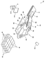
[도 1] 본 발명의 일 실시예에 따른 로봇 시스템을 이용하여 골판지 상자의 반송 작업을 수행하고 있는 모습을 도시하는 개략도이다.
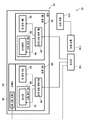
[도 2] 본 발명의 일 실시예에 따른 로봇 시스템의 전체 구성을 도시하는 블록도이다.
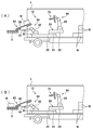
[도 3] 본 발명의 일 실시예에 따른 로봇 시스템의 제1 로봇을 도시하는 도면으로서, (A)가 전체적인 측면도, (B)가 제1 로봇 핸드를 전방에서 본 도면이다.
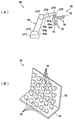
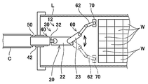
[도 4] 본 발명의 일 실시예에 따른 로봇 시스템의 제2 로봇을 도시하는 도면으로서, (A)가 전체적인 측면도, (B)가 제2 로봇 핸드를 내면 측에서 본 사시도이다.
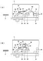
[도 5] 본 발명의 일 실시예에 따른 로봇 시스템을 이용하여 골판지 상자의 반송 작업을 수행하고 있는 모습을 도시하는 측면도로서, (A)가 적재된 골판지 상자 중 1 개를 유지한 때의 도면, (B)가 컨베이어의 반송면 상에서 골판지 상자를 해방할 때의 도면이다.
[도 6] 본 발명의 일 실시예에 따른 로봇 시스템을 이용하여 골판지 상자의 반송 작업을 수행하고 있는 모습을 도시하는 측면도로서, (A)가 컨베이어의 반송면이 거치형 컨베이어의 반송면과 연속적으로 되도록 제1 로봇의 자세를 변경하였을 때의 도면, (B)가 거치형 컨베이어에의 골판지 상자의 반송 작업이 완료된 때의 도면이다.
[도 7] 본 발명의 일 실시예에 따른 로봇 시스템의 가동부의 구동 형태를 설명하기 위한 도면으로서, 트럭의 화물대를 일부 파단하여 상방에서 본 때의 도면이다.
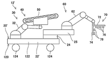
[도 8] 본 발명의 일 실시예에 따른 로봇 시스템의 제1 변형예의 로봇을 도시하는 측면도이다.
[도 9] 본 발명의 일 실시예에 따른 로봇 시스템의 제2 변형예의 로봇을 도시하는 측면도이다.[Fig. 1] A schematic diagram showing a state in which a corrugated cardboard box is transported using a robot system according to an embodiment of the present invention.
2 is a block diagram showing the overall configuration of a robot system according to an embodiment of the present invention.
[Fig. 3] A diagram showing a first robot of the robot system according to an embodiment of the present invention, in which (A) is an overall side view, and (B) is a view as viewed from the front of the first robot hand.
[Fig. 4] A diagram showing a second robot of the robot system according to an embodiment of the present invention, in which (A) is an overall side view, and (B) is a perspective view of the second robot hand as viewed from the inner side.
[Fig. 5] A side view showing a state in which a corrugated cardboard box is transported using a robot system according to an embodiment of the present invention, and a view when one of the corrugated cardboard boxes loaded with (A) is maintained. , (B) is a diagram when the corrugated cardboard box is released from the conveying surface of the conveyor.
[Fig. 6] As a side view showing a state in which a corrugated cardboard box is conveyed by using the robot system according to an embodiment of the present invention, (A) is the conveying surface of the conveyor continuously and the conveying surface of the stationary conveyor. The figure when the posture of the 1st robot is changed as much as possible, (B) is a figure when the conveyance work of a corrugated cardboard box to a stationary conveyor is completed.
[Fig. 7] A diagram for explaining a driving mode of a movable part of a robot system according to an embodiment of the present invention, which is a view when a cargo stand of a truck is partially broken and viewed from above.
Fig. 8 is a side view showing the robot of the first modified example of the robot system according to the embodiment of the present invention.
Fig. 9 is a side view showing a robot of a second modified example of the robot system according to an embodiment of the present invention.
이하에서, 본 발명의 일 실시예에 따른 로봇 및 이를 구비한 로봇 시스템에 대해 도면을 참조하여 설명한다. 한편, 본 실시예에 의해 본 발명이 한정되는 것은 아니다. 또한, 이하에서는, 모든 도면을 통해 동일 또는 대응하는 요소에는 동일한 참조 부호를 부여하고, 그 중복된 설명을 생략한다.Hereinafter, a robot according to an embodiment of the present invention and a robot system including the same will be described with reference to the drawings. On the other hand, the present invention is not limited by this embodiment. In addition, in the following, the same reference numerals are assigned to the same or corresponding elements throughout all the drawings, and redundant descriptions thereof are omitted.
(로봇 시스템(10))(Robot system (10))
도 1은 본 실시예에 따른 로봇 시스템을 이용하여 골판지 상자의 반송 작업을 수행하고 있는 모습을 도시하는 개략도이다. 도 2는 동(同) 로봇 시스템의 전체 구성을 도시하는 블록도이다. 도 1에 도시된 바와 같이, 본 실시예에 따른 로봇 시스템(10)은 피포장물을 포장한 상태로 밀봉이 된 골판지 상자(W)(워크)의 반송 작업을 수행한다. 구체적으로는, 로봇 시스템(10)은 트럭의 화물칸(L)(도 5 ~ 7 참조)에 적재된 복수의 골판지 상자(W)를 1 개씩 트럭의 화물칸(L)의 외부에 배치된 거치형 컨베이어(C)까지 반송하는 작업을 수행한다. 여기서, 도 1에서는 보기가 번잡하지 않도록, 트럭의 화물칸(L)의 도시는 생략되어 있다.1 is a schematic diagram showing a state in which a corrugated cardboard box is transported using a robot system according to the present embodiment. 2 is a block diagram showing the overall configuration of the robot system. As shown in Fig. 1, the
도 1에 도시되는 바와 같이, 본 실시예에 따른 로봇 시스템(10)은 로봇(12)과, 당해 로봇(12)을 원격 조작하기 위한 조작부(110)를 구비한다. 또한, 로봇 시스템(10)은 로봇(12)의 작업 상황을 촬상하기 위한 촬상 장치(112)와, 당해 촬상 장치(112)에서 영상 정보를 출력하기 위한 출력 장치(114)를 더 구비한다.As shown in FIG. 1, the
(로봇(12))(Robot (12))
도 1에 도시된 바와 같이, 로봇(12)은 베이스(20)와, 베이스(20)에 그 기단부가 고정되는 제1 로봇(30)과, 마찬가지로 베이스(20)에 그 기단부가 고정되는 제2 로봇(60)을 구비한다.As shown in FIG. 1, the
(베이스(20))(Base (20))
베이스(20)는 판상으로 형성되는 베이스 본체(22)와, 베이스 본체(22)에 설치되는 가동부(23)를 구비한다. 베이스 본체(22)는, 두께 방향에서 볼 때 직사각형이고, 후술하는 트럭의 화물칸(L)의 저판에 재치된다. 가동부(23)는 베이스 본체(22)로부터 연장되는 선회축(24)과, 당해 선회축(24)에 장착됨으로써, 로봇(12)의 길이 방향과 폭 방향이 교차하는 평면 상에서 선회축(24)을 중심으로 요동 가능한 가동부 본체(25)를 구비한다.The
또한, 가동부(23)는, 조작부(110)로부터의 조작 정보 등에 기초하여, 미리 기억부(미도시)에 격납된 프로그램에 따라, 자신의 동작을 제어하는 가동부 제어 장치(29)를 더 구비한다. 가동부 제어 장치(29)에 대한 구체적인 구성은 특별히 한정되지 않지만, 예를 들어, 공지의 프로세서(CPU 등)가 기억부(메모리 등)에 격납된 프로그램에 따라 동작함으로써 실현되는 구성이라도 좋다.In addition, the
한편, 이하의 설명에서, 제1 로봇(30)의 기단과 제2 로봇(60)의 기단을 잇는 방향을 로봇(12)의 길이 방향으로 칭하고, 베이스 본체(22)의 두께 방향과 일치하고, 또한, 상기 길이 방향에 직교하는 방향을 로봇(12)의 높이 방향으로 칭하고, 베이스 본체(22)의 폭 방향과 일치하고, 또한, 상기 길이 방향 및 상기 높이 방향에 직교하는 방향을 로봇(12)의 폭 방향으로 칭한다.On the other hand, in the following description, the direction connecting the base end of the
한편, 본 실시예에서는, 후술하는 바와 같이 제2 로봇(60)이 가동부(23)에 의해 이동 가능하다. 따라서, 상기 로봇(12)의 길이 방향은, 정확하게는 가동부 본체(25)의 길이 방향이 베이스 본체(22)의 길이 방향과 일치하는 로봇(12)의 초기 상태에서 제1 로봇(30)의 기단과 제2 로봇(60)의 기단을 잇는 방향이다. 또는, 다시 말해서, 제1 로봇(30)의 기단과 가동부(23)의 선회축(24)의 기단을 잇는 방향이다.On the other hand, in this embodiment, the
(제1 로봇(30))(The first robot (30))
도 3은 본 실시예에 따른 로봇 시스템의 제1 로봇을 도시하는 도면으로서, (A)가 전체적인 측면도, (B)가 제1 로봇 핸드를 전방에서 본 도면이다. 도 3(A)에 도시된 바와 같이, 제1 로봇(30)은 제1 로봇 암(32)과, 당해 제1 로봇 암(32)의 선단에 장착되는 제1 로봇 핸드(40)를 구비한다. 또한, 도 2에 도시된 바와 같이, 제1 로봇(30)은 제1 로봇 암(32) 및 제1 로봇 핸드(40)의 동작을 제어하기 위한 제1 로봇 제어 장치(59)를 더 구비한다. 제1 로봇(30)은 수직 다관절형 로봇으로 구성되어 있다.3 is a diagram showing a first robot of the robot system according to the present embodiment, in which (A) is an overall side view and (B) is a view as viewed from the front of the first robot hand. As shown in FIG. 3(A), the
(제1 로봇 암(32))(The first robot arm (32))
도 3(A)에 도시된 바와 같이, 제1 로봇(30)은 4 개의 관절축(JT1 ~ JT4)과, 이러한 관절축에 의해 순차적으로 연결되는 4 개의 링크(34a ~ 34d)을 구비하는 다관절 암이다.As shown in Fig. 3(A), the
제1 관절축(JT1)은 베이스 본체(22)의 상면과 제1 링크(34a)의 기단부를 연직 방향으로 연장되는 축 둘레로 회전 가능하게 연결한다. 또한, 제2 관절축(JT2)은 제1 링크(34a)의 선단부와 제2 링크(34b)의 기단부를 수평 방향으로 연장되는 축 둘레로 회전 가능하게 연결한다. 또한, 제3 관절축(JT3)은 제2 링크(34b)의 선단부와 제3 링크(34c)의 기단부를 수평 방향으로 연장되는 축 둘레로 회전 가능하게 연결한다.The first joint shaft JT1 rotatably connects the upper surface of the
또한, 제4 관절축(JT4)은 제3 링크(34c)의 선단부와 제4 링크(34d)의 기단부를 제3 링크(34c)의 길이 방향과 직교하는 방향으로 연장되는 축 둘레로 회전 가능하게 연결한다. 그리고, 제4 링크(34d)의 선단부에 제1 로봇 핸드(40)가 장착된다.In addition, the fourth joint shaft JT4 is rotatable around an axis extending in a direction orthogonal to the longitudinal direction of the
(제1 로봇 핸드(40))(1st robot hand (40))
도 3에 도시된 바와 같이, 제1 로봇 핸드(40)는 제1 로봇 암(32)의 선단에 장착되는 기부(42)와, 당해 기부(42)에 고정되는 컨베이어(50)를 구비한다.As shown in FIG. 3, the
기부(42)는, 그 두께 방향에서 볼 때 직사각형인 저판(44)과, 저판(44)의 폭 방향에서 일방 측의 단부 가장자리로부터 세워지는 측판(46a)과, 저판(44)의 폭 방향에서 타방 측의 단부 가장자리로부터 세워지는 측판(46b)을 구비한다. 측판(46a, 46b)은 서로 동일한 형상을 가진다. 측판(46a, 46b)은 각각 그 두께 방향에서 볼 때 사다리꼴이다.The
측판(46a, 46b)은 각각, 도 3(A)에 도시된 바와 같이, 그 두께 방향에서 볼 때, 높이 방향으로 연장되는 윗변 및 아랫변과, 윗변의 높이 방향에서 한쪽 끝(도 3(A)에서 하단)과 아랫변의 높이 방향에서 한쪽 끝(앞과 동일)을 연결하는 제1 다리와, 윗변의 높이 방향에서 다른쪽 끝(도 3(A)에서 상단)과 아랫변의 높이 방향에서 다른쪽 끝(앞과 동일)을 연결하는 제2 다리를 구비한다. 도 3(A)에서, 상기 제1 다리가 수평 방향으로 연장되고, 또한, 상기 제2 다리가 컨베이어(50)의 반송 방향에서 하류 측을 향하도록 하방으로 기울어져 있다.
컨베이어(50)는 벨트 컨베이어로 구성된다. 컨베이어(50)는 반송 방향에서 서로 인접하여 병렬되는 복수의 롤러(52)와, 복수의 롤러(52) 각각의 회전축을 축 지지하기 위한 한 쌍의 샤프트(54a, 54b)와, 복수의 롤러(52)에 고리 형태로 팽팽하게 설치되는 반송 벨트(56)와, 복수의 롤러(52) 중 적어도 하나를 회전 구동하기 위한 도시하지 않은 전기 모터를 구비하는 공지의 구조이다.The
샤프트(54a)는 기부(42)의 측판(46a)의 내면에서 상단 가장자리를 따라 당해 기부(42)의 측판(46a)에 그 길이 치수의 중앙부가 장착된다. 또한, 샤프트(54b)는 기부(42)의 측판(46b)의 내면에서 상단 가장자리를 따라 당해 기부(42)의 측판(46b)에 그 길이 치수의 중앙부가 장착된다.The shaft 54a is attached to the
따라서, 도 3(A)에서 한 쌍의 샤프트(54a, 54b)는 각각 기부(42)의 측판(46a, 46b) 각각의 상기 제2 다리와 동일한 각도만큼, 컨베이어(50)의 반송 방향에서 하류 측을 향함에 따라서 하방으로 기울어져 있다.Accordingly, in FIG. 3(A), the pair of shafts 54a and 54b are downstream in the conveying direction of the
이에 따라서, 컨베이어(50) 전체가 기부(42)의 측판(46a, 46b) 각각의 상기 제2 다리와 동일한 각도만큼, 그 반송 방향에서 하류 측을 향함에 따라서 하방으로 기울어져 있다. 즉, 컨베이어(50)의 반송면(58)도 동일하게 기울어져 있다.Accordingly, the
(제1 로봇 제어 장치(59))(The first robot control device (59))
도 2에 도시된 바와 같이, 로봇 제어 장치(59)는, 조작부(110)로부터의 조작 정보 등에 기초하여, 미리 기억부(미도시)에 격납된 프로그램에 따라서, 제1 로봇 암(32) 및 컨베이어(60)의 동작을 제어한다. 제1 로봇 제어 장치(59)에 대한 구체적인 구성은 특별히 한정되지 않지만, 예를 들어, 공지의 프로세서(CPU 등)가 기억부(메모리 등)에 격납된 프로그램에 따라 동작함으로써 실현되는 구성이라도 좋다.As shown in Fig. 2, the
(제2 로봇(60))(2nd robot (60))
도 4는 본 실시예에 따른 로봇 시스템의 제2 로봇을 도시하는 도면이고, (A)가 전체적인 측면도, (B)가 제2 로봇 핸드를 내면 측에서 본 사시도이다. 도 4(A)에 도시된 바와 같이, 제2 로봇(60)은 제2 로봇 암(62)과, 당해 제2 로봇 암(62)의 선단에 장착되는 제2 로봇 핸드(70)를 구비한다. 또한, 도 2에 도시된 바와 같이, 제2 로봇(60)은 제2 로봇 암(62) 및 제2 로봇 핸드(70)의 동작을 제어하기 위한 제2 로봇 제어 장치(89)를 더 구비한다. 제2 로봇(60)은 수직 다관절형 로봇으로 구성되어 있다.Fig. 4 is a diagram showing a second robot of the robot system according to the present embodiment, where (A) is an overall side view, and (B) is a perspective view of the second robot hand as viewed from the inner side. As shown in FIG. 4A, the
(제2 로봇 암(62))(2nd robot arm (62))
도 4(A)에 도시된 바와 같이, 제2 로봇(60)은 6 개의 관절축(JT1' ~ JT6')과, 이러한 관절축에 의해 순차적으로 연결되는 6 개의 링크(64a ~ 64f)를 구비하는 다관절 암이다.As shown in Figure 4 (A), the
제1 관절축(JT1')은 가동부 본체(25)의 선단부에서 상면과 제1 링크(64a)의 기단부를 연직 방향으로 연장되는 축 둘레로 회전 가능하게 연결한다. 또한, 제2 관절축(JT2')는 제1 링크(64a)의 선단부와 제2 링크(64b)의 기단부를 수평 방향으로 연장되는 축 둘레로 회전 가능하게 연결한다. 또한, 제3 관절축(JT3')은 제2 링크(64b)의 선단부와 제3 링크(64c)의 기단부를 수평 방향으로 연장되는 축 둘레로 회전 가능하게 연결한다.The first joint shaft JT1 ′ rotatably connects the upper surface at the distal end of the
제4 관절축(JT4')은 제3 링크(64c)의 선단부와 제4 링크(64d)의 기단부를 제3 링크(64c)의 길이 방향과 직교하는 방향으로 연장되는 축 둘레로 회전 가능하게 연결한다. 또한, 제5 관절축(JT5')은 제4 링크(64d)의 선단부와 제5 링크(64e)의 기단부를 제4 링크(64d)의 길이 방향과 직교하는 방향으로 연장되는 축 둘레로 회전 가능하게 연결한다. 또한, 제6 관절축(JT6')은 제5 링크(64e)의 선단부와 제6 링크(64f)의 기단부를 비틀림 회전 가능하게 연결한다. 그리고, 제6 링크(64f)의 선단부에 제2 로봇 핸드(70)가 장착된다.The fourth joint shaft JT4' is rotatably connected around an axis extending in a direction perpendicular to the longitudinal direction of the
(제2 로봇 핸드(70))(2nd robot hand (70))
도 4(B)에 도시된 바와 같이, 제2 로봇 핸드(70)는 그 두께 방향에서 볼 때 직사각형인 제1 판상 부재(72)와, 그 두께 방향에서 볼 때 직사각형인 제2 판상 부재(74)와, 제1 판상 부재(72) 및 제2 판상 부재(74) 각각의 내면에 복수 설치되는 흡착부(76)를 구비한다.As shown in Fig. 4B, the
제1 판상 부재(72)의 기단부의 외면에서 길이 치수의 중앙부가 제6 링크(64f)의 선단부에 장착된다. 제2 판상 부재(74)는 제1 판상 부재(72)와 동일한 길이 치수를 가지고 있다. 그리고, 제1 판상 부재(72)의 길이 방향으로 연장하는 폭 방향의 단부 가장자리와, 제2 판상 부재(74)의 길이 방향으로 연장하는 폭 방향의 단부 가장자리가 서로 접속됨으로써, 도 4(A)에 도시된 바와 같이 측면에서 볼 때 L 자 형상의 구조가 된다.The central portion of the length dimension on the outer surface of the base end portion of the
제1 판상 부재(72)의 내면에는, 그 폭 방향을 따라 3 행, 그 길이 방향을 따라 5 열의 3 × 5 행렬로 총 15 개의 흡착부(76)가 병렬로 설치되어 있다. 또한, 제2 판상 부재(74)의 내면에는, 그 폭 방향을 따라 2 행, 그 길이 방향을 따라 5 열의 2 × 5 행렬에 총 10 개의 흡착부(76)가 병렬로 설치되어 있다. 즉, 제2 로봇 핸드(70)는 총 25 개의 흡착부(76)를 구비하고 있다.On the inner surface of the first plate-
25 개의 흡착부(76)는 각각 중공의 테이퍼 형상으로 형성되어 있고, 그 끝이 가는 선단이 제1 판상 부재(72) 또는 제2 판상 부재(74)에 장착된다. 흡착부(76)는 각각 도시하지 않은 진공 발생 장치에 접속되어서, 내부가 부압 상태가 된다. 25 개의 흡착부(76)는 상기 부압에 의해 골판지 상자(W)의 상면 및 측면을 흡착하여, 1 개의 판지 상자(W)를 협동하여 유지할 수 있다.Each of the 25
(제2 로봇 제어 장치 (89))(2nd robot control device (89))
도 2에 도시된 바와 같이, 제2 로봇 제어 장치(89)는, 조작부(110)로부터의 조작 정보 등에 기초하여, 미리 기억부(미도시)에 격납된 프로그램에 따라서, 제2 로봇 암(62) 및 흡착부(76)(유지부)의 동작을 제어한다. 제2 로봇 제어 장치(89)에 대한 구체적인 구성은 특별히 한정되지 않지만, 상기 제1 로봇 제어 장치(59)와 마찬가지로, 예를 들어, 공지의 프로세서(CPU 등)가 기억부(메모리 등)에 격납된 프로그램에 따라 동작함으로써 실현되는 구성이라도 좋다.As shown in Fig. 2, the second
(조작부(110))(Operation unit (110))
도 1에 도시된 바와 같이, 조작부(110)는, 오퍼레이터(P)로부터의 수동에 의한 지령 값에 기초하여, 로봇(12)을 원격 조작하기 위해, 당해 로봇(12)으로부터 소정의 거리만큼 이격되어 설치된다.As shown in FIG. 1, the
조작부(110)의 구체적인 구성은 특별히 한정되지 않지만, 예를 들어, 핸들의 변위를 지령 값으로 받아들이는 구성이라도 좋고, 버튼을 누르는 동작 등을 지령 값으로 받아들이는 구성이라도 좋고, 또는, 화면 상의 표시가 눌리는 것 등을 지령 값으로 받아들이는 터치 패널의 구성이라도 좋다. 또한, 조작부(110)는 음성을 지령 값으로 받아들이는 구성이라도 좋고, 또는, 그 밖의 구성이라도 좋다.The specific configuration of the
조작부(110)는 오퍼레이터(P)로부터의 수동에 의한 지령 값을 받아들여서 조작 정보를 생성하고, 당해 조작 정보를 제1 로봇 제어 장치(59), 제2 로봇 제어 장치(89) 및 가동부 제어 장치(29)에 송신한다.The
(촬상 장치(112))(Imaging device 112)
촬상 장치(112)는 로봇(12)의 작업 상황을 촬상하여 동영상 정보를 취득하기 위해 설치된다. 촬상 장치(112)의 구성은 특별히 한정되지 않지만, 예를 들어, 공지의 비디오 카메라로 구성되어도 좋다.The
(출력 장치(114))(Output device (114))
출력 장치(114)는 촬상 장치(112)로 촬상된 동영상 정보를 출력하기 위한 디스플레이 장치로 구성된다. 출력 장치(114)의 구체적인 구성은 특별히 한정되지 않지만, 예를 들어, 액정 디스플레이(Liquid Crystal Display)로 구성되어도 좋고, 유기 EL 디스플레이(Organic Electro-Luminescence Display)로 구성되어도 좋고, 또는, 그 밖의 장치로 구성되어도 좋다.The
(반송 작업의 일례)(Example of return operation)
도 5 ~ 7을 기초로, 본 실시예에 따른 로봇 시스템(10)에 의해 수행되는 반송 작업의 일례에 대해 설명한다. 여기에서는, 상술한 바와 같이, 로봇 시스템(10)을 이용하여, 트럭의 화물칸(L)에 적재된 복수의 골판지 상자(W)를 1 개씩 트럭의 화물칸(L)의 외부에 배치된 거치형 컨베이어(C)까지 반송하는 작업을 수행하는 경우를 예로 들어 설명한다.An example of a conveyance operation performed by the
한편, 이하의 반송 작업의 일례에서는, 오퍼레이터(P)는, 출력 장치(114)로부터 출력되는 동영상 정보에 기초하여, 로봇(12)의 작업 상황을 파악하면서, 조작부(110)에 대해 지령 값을 입력하여도 좋다. 여기서, 출력 장치(114)로부터 출력되는 동영상 정보는 촬상 장치(112)를 이용하여 로봇(12)의 작업 상황을 촬상한 것이다.On the other hand, in an example of the following conveyance operation, the operator P, based on the moving picture information output from the
도 5는 본 실시예에 따른 로봇 시스템을 이용하여 골판지 상자의 반송 작업을 수행하고 있는 모습을 도시하는 측면도로서, (A)가 적재된 골판지 상자 중 1 개를 유지할 때의 도면, (B)가 컨베이어의 반송면 상에서 골판지 상자를 해방하는 때의 도면이다. 또한, 도 6은 동 로봇 시스템을 이용하여 골판지 상자의 반송 작업을 수행하고 있는 모습을 도시하는 측면도로서, (A)가 컨베이어의 반송면이 거치형 컨베이어의 반송면과 연속적이 되도록 제1 로봇의 자세를 변경하였을 때의 도면, (B)가 거치형 컨베이어로의 골판지 상자의 반송 작업이 완료된 때의 도면이다. 또한, 도 7은 본 실시예에 따른 로봇 시스템의 가동부의 구동 형태를 설명하기 위한 도면으로서, 트럭의 화물칸을 일부 파단하여 상방에서 볼 때의 도면이다.FIG. 5 is a side view showing a state in which a corrugated cardboard box is transported by using the robot system according to the present embodiment, and (B) is a view when one of the cardboard boxes loaded with (A) is maintained. It is a drawing when the corrugated cardboard box is released from the conveyance surface of a conveyor. In addition, FIG. 6 is a side view showing a state in which a corrugated cardboard box is conveyed using the robot system, where (A) is the posture of the first robot so that the conveying surface of the conveyor is continuous with the conveying surface of the stationary conveyor. A drawing when is changed, (B) is a drawing when the conveying operation of the corrugated cardboard box to the stationary conveyor is completed. 7 is a view for explaining the driving mode of the movable part of the robot system according to the present embodiment, and is a view when viewed from above by partially breaking the cargo compartment of the truck.
먼저, 오퍼레이터(P)는, 조작부(110)를 이용하여, 컨베이어(50)의 반송 벨트(56)을 정지 상태로 한다. 또한, 오퍼레이터(P)는, 조작부(110)를 이용하여, 컨베이어(50)의 반송면(58)의 상류단이 제2 로봇 암(62)의 선단의 가동 범위 내에 위치하도록, 제1 로봇 암(32)의 자세를 변경한다.First, the operator P puts the
다음으로, 오퍼레이터(P)는, 조작부(110)를 이용하여, 제2 로봇 핸드(70)의 제1 판상 부재(72)의 내면에 설치되는 15 개의 흡착부(76)가 복수의 골판지 상자(W) 중 가장 상단에 위치하는 1 개의 판지 상자(W)(이하, 「최상단의 골판지 상자(W)」라고 칭한다)의 상면에 접촉하도록, 또한, 제2 로봇 핸드(70)의 제2 판상 부재(74)의 내면에 설치되는 10 개 흡착부(76)가 최상단의 골판지 상자(W)의 측면에 접촉하도록, 제2 로봇 암(62)의 자세를 변경한다.Next, the operator P uses the
또한, 오퍼레이터(P)는, 조작부(110)를 이용하여, 도시하지 않은 진공 발생 장치를 구동하고, 흡착부(76) 내를 부압 상태로 한다. 이에 따라서, 제1 판상 부재(72)의 내면에 설치되는 흡착부(76)가 최상단의 골판지 상자(W)의 상면을 흡착하고, 또한, 제2 판상 부재(74)의 내면에 설치되는 흡착부(76)가 최상단의 골판지 상자(W)의 측면의 흡착하여, 당해 최상단의 골판지 상자(W)를 유지할 수 있다. 이 때의 상태가 도 5(A)에 도시된다.In addition, the operator P drives a vacuum generator (not shown) using the
또한, 오퍼레이터(P)는, 조작부(110)를 이용하여, 제2 로봇 핸드(70)의 흡착부(76)로 흡착하여 유지된 골판지 상자(W)의 저면이 제1 로봇 핸드(40)의 컨베이어(50)의 반송면(58)의 상류 부분에 맞닿도록, 제2 로봇 암(62)의 자세를 변경한다.In addition, the operator P uses the
그리고, 오퍼레이터(P)는, 조작부(110)를 이용하여, 도시하지 않은 진공 발생 장치를 정지하고, 흡착부(76)에 흡착된 상태로부터 골판지 상자(W)를 해방한다. 이에 따라서, 제2 로봇(60)은 흡착부(76)(유지부)로 유지한 골판지 상자(W)를 제1 로봇(30)의 컨베이어(50)의 반송면(58)에 올리고 해방하는 동작을 수행한다. 이 때의 상태가 도 5(B)에 도시된다.Then, the operator P uses the
다음으로, 오퍼레이터(P)는, 조작부(110)를 이용하여, 컨베이어(50)의 반송면(58)이 거치형 컨베이어(C)의 반송면의 상류 측에서 당해 거치형 컨베이어(C)의 반송면과 서로 연속하도록, 제1 로봇 암(32)의 자세를 변경한다. 이 때의 상태가 도 6(A)에 도시된다.Next, the operator P uses the
최후로, 오퍼레이터(P)는, 조작부(110)를 이용하여, 컨베이어(50)의 반송 벨트(56)를 구동시킨다. 이에 따라서, 컨베이어(50)의 반송면(58) 상에 재치된 골판지 상자(W)가 당해 반송면(58)의 하류 측으로 이동하고, 당해 반송면(58)의 하류단으로부터 거치형 컨베이어(C)의 반송면의 상류 부분에 전달된다.Finally, the operator P drives the
상술한 반송 작업을 반복함으로써, 로봇 시스템(10)은 트럭의 화물칸(L)에 적재된 복수의 골판지 상자(W) 모두를 트럭의 화물칸(L)의 외부에 배치된 거치형 컨베이어(C)의 반송면까지 반송할 수 있다. 여기서, 거치형 컨베이어(C)는 컨베이어(50)와 마찬가지로 벨트 컨베이어로 구성되어도 좋다. 당해 벨트 컨베이어는 공지의 구조라도 좋다. 거치형 컨베이어(C)는 컨베이어(50)로부터 그 상류 부분에서 골판지 상자(W)를 수취하면, 당해 골판지 상자(W)를 원하는 반송처까지 더 반송한다.By repeating the above-described conveying operation, the
여기서, 도 7에 도시된 바와 같이 오퍼레이터(P)는, 조작부(110)를 이용하여, 가동부(23)를 구동시킴으로써(구체적으로는, 가동부(23)의 선회축(24)을 선회시킴으로써), 가동부 본체(25)에 그 기단부가 고정된 제2 로봇(60)을 로봇(12)의 길이 방향과 동 폭 방향이 교차하는 평면 상에서 선회축(24)을 중심으로 회전시킬 수 있다.Here, as shown in FIG. 7, the operator P drives the
(효과)(effect)
본 실시예에 따른 로봇(12)은 제1 로봇 암(32)의 선단에 컨베이어(50)가 장착되어 있기 때문에, 제1 로봇 암(32)의 선단이 이동 가능한 범위에서 컨베이어(50)를 이동시킬 수 있다. 또한, 제2 로봇(60)이 흡착부(76)(유지부)로 흡착하여 유지하는 골판지 상자(W)(워크)를 컨베이어(50)의 반송면(58)에 올리고 해방하는 것이 가능하다. 그 결과, 설치 장소가 한정적이지 않고, 이동 가능한 컨베이어(50)에 의해 골판지 상자(W)(워크)를 반송하는 것이 가능한 로봇(12)을 제공하는 것이 가능하다.In the
본 실시예에 따른 로봇(12)은, 베이스 본체(22)에 설치되는 가동부(23)에 의해, 제2 로봇(60)이 로봇(12)의 폭 방향 및 길이 방향으로 이동 가능하기 때문에, 반송 대상이 되는 골판지 상자(W)가 제2 로봇 암(62)의 선단의 가동 범위보다 멀리 배치되어 있는 경우에도, 상기 골판지 상자(W)를 흡착부(76)로 유지할 수 있도록 제2 로봇 암(62)의 자세를 용이하게 변경하는 것이 가능하다. 그 결과, 본 발명이 나타내는 효과를 현저하게 할 수 있다.In the
본 실시예에서는, 가동부(23)는 선회축(24)과, 당해 선회축(24)에 장착되는 가동부 본체(25)를 구비하고, 제2 로봇(60)은, 그 기단부가 가동부 본체(25)에 고정됨으로써, 로봇(12)의 길이 방향과 동 폭 방향이 교차하는 평면 상에서 선회축(24)을 중심으로 회전할 수 있다. 이에 따라서, 제2 로봇(60)은 상기 폭 방향 및 상기 길이 방향으로 이동 가능한 구조이다. 따라서, 간단한 구조의 가동부(23)에 의해 제2 로봇(60)을 상기 폭 방향 및 상기 길이 방향으로 이동시키는 것이 가능하다.In this embodiment, the
본 실시예에서는, 유지부가 골판지 상자(W)(워크)를 흡착하여 유지하는 흡착부(76)로 구성되기 때문에, 예를 들어, 간격없이 적재된 복수의 골판지 상자(W) 중에서 1 개의 골판지 상자(W)를 유지하는 경우에도, 당해 1 개의 골판지 상자(W)의 측부를 흡착하여, 다른 골판지 상자(W)에 방해받지 않고 용이하게 당해 1 개의 골판지 상자(W)를 유지하는 것이 가능하다.In the present embodiment, since the holding portion is composed of the
본 실시예에 따른 로봇 시스템(10)은 상기 로봇(12)을 구비하여, 당해 로봇(12)과 동일한 효과를 나타낸다.The
본 실시예에서는, 제1 로봇(30) 및 제2 로봇(60)은 각각 수직 다관절형 로봇으로 구성된다. 이에 따라서, 제1 로봇 암(32) 및 제2 로봇 암(62)이 각각 원하는 자세를 취하기 쉬워진다. 그 결과, 본 발명이 나타내는 효과를 현저하게 할 수 있다.In this embodiment, the
본 실시예에서는 제1 로봇 암(32)은 4 개의 관절축(JT1 ~ JT4)을 구비하기 때문에, 제1 로봇 암(32)이 원하는 자세를 취하기 쉬워진다. 이에 따라서, 제1 로봇 핸드(40) 및 컨베이어(50)를 원하는 위치로 이동시키기 쉬워진다. 그 결과, 본 발명이 나타내는 효과를 현저하게 할 수 있다.In this embodiment, since the
본 실시예에서는, 제2 로봇 암(62)은 6 개의 관절축(JT1' ~ JT6')을 구비하기 때문에, 제2 로봇 암(62)이 원하는 자세를 취하기 쉬워진다. 이에 따라서, 제2 로봇 핸드(70) 및 흡착부(76)를 원하는 위치로 이동시키기 쉬워진다.In this embodiment, since the
본 실시예에서는, 조작부(110)를 이용하여 로봇(12)을 원격 조작할 수 있다. 그 결과, 더욱 설치 장소가 한정적이지 않고, 이동 가능한 컨베이어(50)에 의해 골판지 상자(W)를 반송하는 것이 가능하다.In this embodiment, the
본 실시예에서는, 오퍼레이터(P)는, 출력 장치(114)로부터 출력되는 동영상 정보(정보)에 기초하여, 로봇(12)의 작업 상황을 정확하게 파악하면서, 조작부(110)에 지령 값을 입력할 수 있다.In this embodiment, the operator P inputs a command value to the
(변형예)(Modified example)
상기 설명으로부터, 당업자에게는 본 발명의 많은 개량이나 다른 실시 형태가 분명할 것이다. 따라서, 상기 설명은 예시로서만 해석되어야 하며, 본 발명을 실행하는 최선의 형태를 당업자에게 교시할 목적으로 제공된 것이다. 본 발명의 사상을 벗어나지 않고 그 구조 및/또는 기능의 상세를 실질적으로 변경할 수 있다.From the above description, many improvements and other embodiments of the present invention will be apparent to those skilled in the art. Accordingly, the above description is to be construed only as an example, and is provided for the purpose of teaching those skilled in the art the best mode for carrying out the present invention. It is possible to substantially change the details of the structure and/or function without departing from the spirit of the present invention.
(제1 변형예)(1st modification)
도 8에 기초하여, 상기 실시예에 따른 로봇 시스템의 제1 변형예를 설명한다. 여기서, 본 변형예에 따른 로봇 시스템은 베이스(20)의 구조를 제외하고, 상기에서 설명한 로봇 시스템(10)과 동일한 구성을 구비한다. 따라서, 동일 부분에는 동일한 참조 번호를 부여하고, 동일하게 되는 설명은 반복하지 않는다.Referring to Fig. 8, a first modified example of the robot system according to the above embodiment will be described. Here, the robot system according to the present modified example has the same configuration as the
도 8은 상술한 실시예에 따른 로봇 시스템의 제1 변형예의 로봇을 도시하는 측면도이다. 도 8에 도시된 바와 같이, 본 변형예의 로봇(12')의 베이스(20')는 AGV(120)(Automated Guided Vehicle, 무인 반송차)를 구비한다.Fig. 8 is a side view showing the robot of the first modified example of the robot system according to the above-described embodiment. As shown in Fig. 8, the base 20' of the robot 12' of this modified example is provided with an AGV 120 (Automated Guided Vehicle).
AGV(120)는 판상으로 형성되는 차체(122)와, 당해 차체(122)의 저면에 장착되는 복수의 차륜(124)과, AGV(120)의 동작을 제어하기 위한 AGV 제어 장치(128)를 구비한다.The
판상으로 형성된 차체(122)의 상면에 제1 로봇(30)의 기단이 고정되고, 또한, 가동부(23)의 선회축(24)의 기단이 축 지지된다. 즉, 본 변형예에서는, 당해 차체(122)가 상술한 실시예에서 베이스 본체(22)를 구성하고 있다.The base end of the
AGV 제어 장치(128)는, 조작부(110)로부터의 조작 정보 등에 기초하여, 미리 기억부(미도시)에 격납된 프로그램에 따라서, AGV(120)의 동작을 제어한다. AGV 제어 장치(128)에 관한 구체적인 구성은 특별히 한정되지 않지만, 예를 들어, 공지의 프로세서(CPU 등)가 기억부(메모리 등)에 격납된 프로그램에 따라 동작함으로써 실현되는 구성이라도 좋다.The AGV control device 128 controls the operation of the
한편, AGV 제어 장치(128)는, 예를 들어, 작업 현장의 바닥에 매설된 전선으로부터 미약한 유도 전류를 검출하고, 이러한 검출 값에 기초하여, AGV(120)의 동작을 제어하여도 좋다. 이 때, 조작부(110)로부터의 조작 정보는 필요에 따라 수신하여도 좋다.On the other hand, the AGV control device 128 may detect, for example, a weak induced current from an electric wire buried in the floor of a work site, and control the operation of the
본 변형예에 따르면, 로봇(12)을 용이하게 이동시킬 수 있기 때문에, 본 발명이 나타내는 효과를 현저하게 하는 것이 가능하다. 예를 들어, 상술한 실시예에서, 도 7에 도시된 바와 같이, 제2 로봇(60)은 제2 로봇 암(62)의 선단의 가동 범위보다 먼 트럭의 화물칸(L)의 폭 방향의 단부에 재치되어 있는 골판지 상자(W)를 유지하는 것이 가능해질 뿐만 아니라, AGV(120)에 의해 이동하여 제2 로봇 암(62)의 선단의 가동 범위보다 먼 트럭의 화물칸(L)의 길이 방향의 단부에 재치되어 있는 골판지 상자(W)를 유지하는 것도 가능하게 된다.According to this modified example, since the
(제2 변형예)(2nd modification)
도 9에 기초하여, 상기 실시예에 따른 로봇 시스템의 제2 변형예를 설명한다. 여기서, 본 변형예에 따른 로봇 시스템은 제1 로봇 암(32'')의 구조를 제외하고, 상술한 로봇 시스템(10)과 동일한 구성을 구비한다. 따라서, 동일 부분에는 동일한 참조 번호를 부여하고, 동일하게 되는 설명은 반복하지 않는다.Referring to Fig. 9, a second modified example of the robot system according to the above embodiment will be described. Here, the robot system according to the present modified example has the same configuration as the
도 9는 상술한 실시예에 따른 로봇 시스템의 제2 변형예의 로봇을 도시하는 측면도이다. 도 9에 도시된 바와 같이, 본 변형예의 로봇(12'')의 제1 로봇 암(32'')은 베이스 본체(22)의 상면에 그 기단을 연직 방향으로 연장하는 축 둘레로 회전 가능하게 연결되는 제1 링크(34a'')와, 제1 링크(34a'')의 선단에 그 기단을 로봇(12)의 길이 방향으로 미끄럼 이동 가능하게 연결되는 제2 링크(34b'')를 구비한다.9 is a side view showing the robot of the second modified example of the robot system according to the above-described embodiment. As shown in Fig. 9, the
또한, 제1 로봇 암(32'')은 제2 링크(34b'')의 선단에 그 기단을 수평 방향으로 연장하는 축 둘레로 회전 가능하게 연결되는 폭 방향의 양단의 한 쌍의 제3 링크(34c'')와, 한 쌍의 제3 링크(34c'')의 선단에 그 기단을 수평 방향으로 연장하는 축 둘레로 회전 가능하게 연결되고, 제1 로봇 핸드(40)의 베이스(42)에 연결되는 제4 링크(34d'')를 더 구비한다.In addition, the
제1 로봇 암(32'')은, 예를 들어, 상기한 바와 같은 구조를 구비함으로써, 비틀림 회전할 수 없는 것이라도 좋다. 이에 따라서, 제1 로봇 암(32'')을 간단한 구조로 할 수 있다.The
(그 밖의 변형예)(Other variations)
상술한 실시예에서는, 반송 대상이 되는 골판지 상자(W)가 트럭의 화물칸(L)에 있고, 로봇(12)이 당해 트럭의 화물칸(L)에 배치되는 경우를 설명하였으나, 이에 한정되지 않는다. 예를 들어, 로봇(12)은 반송 대상이 되는 골판지 상자(W)가 지면에 재치되고, 로봇(12)이 그 근방에서 지면에 재치되어도 좋고, 다른 장소에 있는 골판지 상자(W)를 반송하기 위해 그 근방에 로봇(12)이 배치되어도 좋다.In the above-described embodiment, the case where the cardboard box W to be conveyed is in the cargo compartment L of the truck and the
상술한 실시예에서는, 반송 대상이 되는 워크가 골판지 상자(W)인 경우를 설명하였지만, 이 경우에 한정되지 않고 워크가 소정의 형상을 가지는 다른 물체(예를 들어, 기계의 조립에 사용하는 부재 및 포장된 식료품 등)이나, 소정의 형상을 가지지 않는 암석이나 튀김 등이라도 좋다.In the above-described embodiment, the case where the workpiece to be transported is a corrugated cardboard box W has been described, but it is not limited to this case, and the workpiece is another object having a predetermined shape (for example, a member used for assembling a machine). And packaged food products, etc.), or rocks or fried foods that do not have a predetermined shape.
상술한 실시예에서는, 컨베이어(50)의 반송면(58)에 골판지 상자(W)가 재치되고, 컨베이어(50)의 반송면(58)이 거치형 컨베이어(C)의 반송면의 상류 측에서 당해 거치형 컨베이어(C)의 반송면과 서로 연속하도록 제1 로봇 암(32)의 자세를 변경하고, 또한, 흡착부(76)에 의해 유지되어 있는 골판지 상자(W)가 해방되고 나서, 처음으로 컨베이어(50)의 반송 벨트(56)가 구동되는 경우를 설명하였다. 그러나, 이 경우에 한정되지 않고, 컨베이어(60)의 이송 벨트(56)가 상시 구동되는 상태에서 반송 작업을 수행하여도 좋다. 이에 따라서, 복수의 골판지 상자(W)를 1 개씩 반송하는 작업을 단시간에 수행하는 것이 가능하다.In the above-described embodiment, the corrugated cardboard box W is placed on the conveying
상술한 실시예에서는, 로봇 시스템(10)이, 도 2의 블록도에 도시된 바와 같이, 로봇(12), 조작부(110), 촬상 장치(112) 및 출력 장치(114)를 구비하는 경우에 대해 설명하였다. 그러나, 이 경우에 한정되지 않고, 로봇 시스템(10)은 또 다른 구성을 구비하여도 좋다. 예를 들어, 로봇 시스템(10)은 상기 실시예에서 골판지 상자(W)의 반송처인 거치형 컨베이어(C)를 더 구비하는 구성이라도 좋다. 이러한 경우, 예를 들어, 오퍼레이터(P)는, 조작부(110)를 이용하여, 당해 거치형 컨베이어(C)의 동작을 제어하도록 구성되어도 좋다.In the above-described embodiment, when the
상술한 실시예에서는, 제1 로봇 암(32)의 자세를 변경하는 것(및 AGV(120)를 이동시키는 것)만으로, 컨베이어(50)의 위치를 변경하는 경우에 대해 설명하였지만, 이에 한정되지 않는다. 예를 들어, 컨베이어(50)는 그 반송 방향과 높이 방향이 교차하는 평면 상에서 기부(42)에 대해 회전 가능하도록 상기 기부(42)에 장착되어도 좋다. 또한, 컨베이어(60)는 한 쌍의 레일을 기부(42)에 설치하고, 당해 레일 상을 이동할 수 있도록 기부(42)에 장착되어도 좋다. 여기서, 이러한 경우, 제1 로봇 제어 장치(59)가 기부(42)의 동작을 더 제어하여도 좋다.In the above-described embodiment, the case of changing the position of the
상술한 실시예에서는, 유지부가 골판지 상자(W)(워크)를 흡착하여 유지하는 25 개의 흡착부(76)로 구성된 경우에 대해 설명하였지만, 이에 한정되지 않는다. 예를 들어, 흡착부(76)는 1 개 이상 24 개 이하, 또는, 26 개 이상 설치되어도 좋다. 또한, 25 개의 흡착부(76)의 형상은 각각 중공의 테이퍼 형상으로 한정되지 않고, 중공의 직육면체 형상이나 원통 형상이라도 좋고, 또는, 그 밖의 형상이라도 좋다. 또한, 유지부는 워크를 파지하여 유지하는 파지부로 구성되어도 좋고, 워크를 그 상면에 재치하여 유지하는 재치부로 구성되어도 좋고, 또는, 그 밖의 구성이라도 좋다.In the above-described embodiment, the case where the holding unit is composed of 25
상술한 실시예에서는, 컨베이어(50)가 벨트 컨베이어로 구성되는 경우를 설명하였으나, 이에 한정되지 않는다. 예를 들어, 컨베이어(50)가 롤러 컨베이어로 구성되어도 좋고, 그 밖의 컨베이어로 구성되어도 좋다.In the above-described embodiment, the case where the
상술한 실시예에서는, 가동부(23)는 선회축(24)과, 당해 선회축(24)에 장착되는 가동부 본체(25)를 구비하는 경우에 대해 설명하였지만, 이에 한정되지 않는다. 예를 들어, 선회축(24)을 높이 방향으로 신축 가능하게 함으로써, 가동부 본체(25) 및 당해 가동부 본체(25)에 고정되는 제2 로봇(60)이 높이 방향으로 이동 가능하게 하여도 좋다.In the above-described embodiment, the case where the
또한, 예를 들어, 가동부(23)는 로봇(12)의 폭 방향을 따라 연장되는 한 쌍의 레일과, 당해 한 쌍의 레일 상을 이동하는 이동자를 구비하는 구조라도 좋다. 이러한 경우, 제2 로봇(60)은, 그 기단부가 상기 이동자에 고정됨으로써, 로봇(12)의 폭 방향에서 이동 가능하다.Further, for example, the
한편, 가동부(23)는 로봇(12)의 길이 방향을 따라 연장되는 동일한 한 쌍의 레일 및 이동자를 구비하여도 좋다. 이에 따라서, 제2 로봇(60)은 로봇(12)의 길이 방향에서 이동 가능하다. 또한, 상기 폭 방향으로 연장되는 레일과 상기 길이 방향으로 연장되는 레일을 모두 설치하여도 좋다. 예를 들어, 상기한 바와 같은 가동부(23)를 필요에 따라 설치함으로써, 제2 로봇(60)은 상기 폭 방향 및 상기 길이 방향 중 적어도 어느 일방에서 이동 가능하여도 좋다. 또한, 로봇(12)은 가동부 (23)를 구비하지 않아도 좋다. 이러한 경우, 제2 로봇(60)의 기단은 베이스 본체(22)에 고정된다. 이에 따라서, 로봇(12)을 더욱 간단한 구조로 할 수 있다.On the other hand, the
상술한 실시예에서는, 베이스 본체(22)가 판상으로 형성되는 경우를 설명하였지만, 이 경우에 한정되지 않는다. 제1 로봇(30)의 기단 및 제2 로봇(60)의 기단을 고정할 수 있는 형상이라면, 예를 들어, 직육면체 형상이나 원기둥 형상 등의 다른 형상이라도 좋다.In the above-described embodiment, the case where the
상술한 실시예에서는, 제1 로봇(30)은 제2 로봇(60)으로부터 골판지 상자(W)를 수취한 후, 컨베이어(50)의 반송면(58)이 거치형 컨베이어(C)의 반송면의 상류 측에서 당해 거치형 컨베이어(C)의 반송면과 서로 연속하도록 제1 로봇 암(32)의 자세를 변경하는 경우에 대해 설명하였지만, 이에 한정되지 않는다. 예를 들어, 컨베이어(50)는, 그 반송면(58)의 상류단이 제2 로봇 암(62)의 선단의 가동 범위 내에 위치하고, 또한, 그 반송면(58)의 하류단이 거치형 컨베이어(C)의 반송면의 상류 부분에 서로 연속하여 배치될 수 있다면, 제2 로봇 암(62)의 자세를 고정한 채로 반송 작업을 수행하여도 좋다. 이에 따라서, 로봇 시스템(10)를 이용하여, 용이하고 신속하게 워크의 반송 작업을 수행하는 것이 가능하다.In the above-described embodiment, after the
상술한 실시예에서는, 제1 로봇(30) 및 제2 로봇(60)이 각각 수직 다관절형 로봇으로 구성된 경우에 대해 설명하였지만, 이에 한정되지 않는다. 예를 들어, 제1 로봇(30) 및 제2 로봇(60)은 각각 극좌표형 로봇으로 구성되어도 좋고, 원통 좌표형 로봇으로 구성되어도 좋으며, 직각 좌표형 로봇으로 구성되어도 좋고, 수평 다관절형 로봇으로 구성되어도 좋고, 또는 그 밖의 로봇으로 구성되어도 좋다. 여기서, 제1 로봇(30) 및 제2 로봇(60)은 각각 서로 다른 형태의 로봇으로 구성되어도 좋다.In the above-described embodiment, the case where the
상술한 실시예에서는, 제1 로봇 암(32)이 4 개의 관절축을 구비하는 경우에 대해 설명하였지만, 이에 한정되지 않는다. 예를 들어, 제1 로봇 암(32)은 5 개 이상의 관절축을 구비하여도 좋다. 또는, 제1 로봇 암(32)은 1 개 이상 3 개 이하의 관절축을 구비하여도 좋다.In the above-described embodiment, a case in which the
상술한 실시예에서는, 제2 로봇 암(62)이 6 개의 관절축을 구비하는 경우에 대해 설명하였지만, 이에 한정되지 않는다. 예를 들어, 제2 로봇 암(62)은 7 개 이상의 관절축을 구비하여도 좋다. 또는, 제2 로봇 암(62)은 1 개 이상 5 개 이하의 관절축을 구비하여도 좋다.In the above-described embodiment, a case in which the
상술한 실시예에서는, 로봇 시스템(10)이 촬상 장치(112) 및 출력 장치(114)를 구비하는 경우에 대해 설명하였지만, 이에 한정되지 않는다. 예를 들어, 로봇 시스템(10)은 촬상 장치(112) 및 출력 장치(114)를 구비하고, 오퍼레이터(P)가 육안으로 확인하여 로봇(12)의 작업 상황을 확인하도록 구성되어도 좋다. 이에 따라서, 로봇 시스템(10)의 구성을 더욱 간단하게 하는 것이 가능하다.In the above-described embodiment, a case where the
상술한 실시예에서는, 로봇 시스템(10)이, 조작부(110)를 이용하여, 오퍼레이터(P)의 지령 값을 입력받고, 당해 지령 값에 기초하여, 로봇(12)을 동작시키는 경우에 대해 설명하였지만, 이에 한정되지 않는다. 예를 들어, 로봇 시스템(10)은 조작부(110)를 구비하지 않는 전자동 시스템으로 구성되어도 좋다.In the above-described embodiment, a case where the
이와 같이 전자동 시스템으로 실현하려면, 예를 들어, 제1 로봇 암(32)의 선단에 근접 센서를 설치하고, 당해 근접 센서에 의한 검출 값 등에 기초하여, 제1 로봇 제어 장치(59)로 제1 로봇 암(32) 및 로봇 핸드(40) 각각의 동작을 제어하게 하여도 좋다. 또는, 제1 로봇 암(32)의 선단에 카메라를 설치하고, 당해 카메라에 의한 화상 정보의 분석 값 등에 기초하여, 제1 로봇 제어 장치(59)로 제1 로봇 암(32) 및 로봇 핸드(40) 각각의 동작을 제어하게 하여도 좋다. 여기서, 제2 로봇 암(62)도 마찬가지이기 때문에, 여기서는 그 설명을 반복하지 않는다.In order to implement such a fully automatic system, for example, a proximity sensor is installed at the tip end of the
10: 로봇 시스템
12: 로봇
20: 베이스
22: 베이스 본체
23: 가동부
24: 선회축
25: 가동부 본체
29: 가동부 제어 장치
30: 제1 로봇
32: 제1 로봇 암
34: 링크
40: 제1 로봇 핸드
42: 기부
44: 저판
46: 측판
50: 컨베이어
52: 롤러
54: 샤프트
56: 반송 벨트
58: 반송면
59: 제1 로봇 제어 장치
60: 제2 로봇
62: 제2 로봇 암
64: 링크
70: 제2 로봇 핸드
72: 제1 판상 부재
74: 제2 판상 부재
76: 흡착부
89: 제2 로봇 제어 장치
110: 조작부
112: 촬상 장치
114: 출력 장치
120: AGV
122: 차체
124: 차륜
128: AGV 제어 장치
JT: 관절축
C: 거치형 컨베이어
L: 트럭의 화물칸
P: 오퍼레이터
W: 골판지 상자10: robot system
12: robot
20: base
22: base body
23: movable part
24: pivot
25: movable part main body
29: moving part control device
30: first robot
32: first robot arm
34: link
40: first robot hand
42: donation
44: bottom plate
46: shroud
50: conveyor
52: roller
54: shaft
56: conveying belt
58: conveying surface
59: first robot control device
60: second robot
62: second robot arm
64: link
70: second robot hand
72: first plate member
74: second plate member
76: adsorption unit
89: second robot control device
110: control panel
112: imaging device
114: output device
120: AGV
122: body
124: wheel
128: AGV control device
JT: joint axis
C: Stationary conveyor
L: truck's cargo compartment
P: Operator
W: corrugated box
Claims (12)
상기 베이스에 그 기단이 고정되는 제1 로봇과,
상기 베이스에 그 기단이 고정되는 제2 로봇을 구비하고,
상기 제1 로봇은 제1 로봇 암과, 상기 제1 로봇 암의 선단에 장착되는 제1 로봇 핸드를 구비하고,
상기 제2 로봇은 제2 로봇 암과, 상기 제2 로봇 암의 선단에 장착되는 제2 로봇 핸드를 구비하며,
상기 제1 로봇 핸드는 컨베이어를 포함하고,
상기 제2 로봇 핸드는 워크를 유지하는 유지부를 포함하고,
상기 제2 로봇은 상기 유지부에 의해 유지된 워크를 상기 제1 로봇의 컨베이어의 반송면에 올려 해방하는 것을 특징으로 하는 로봇.With the bass,
A first robot whose base end is fixed to the base,
And a second robot whose base end is fixed to the base,
The first robot includes a first robot arm and a first robot hand mounted on a tip of the first robot arm,
The second robot includes a second robot arm and a second robot hand mounted on the tip of the second robot arm,
The first robot hand comprises a conveyor,
The second robot hand includes a holding unit for holding the work,
The second robot, wherein the second robot releases the workpiece held by the holding unit by placing it on the conveying surface of the conveyor of the first robot.
상기 베이스는,
베이스 본체와,
상기 베이스 본체에 설치되는 가동부를 구비하고,
상기 제1 로봇은, 그 기단이 상기 베이스 본체에 고정되고,
상기 제2 로봇은, 그 기단이 상기 가동부에 고정됨으로써,
상기 제1 로봇의 기단과 상기 제2 로봇의 기단을 잇는 길이 방향에 직교하는 폭 방향 및 상기 길이 방향 중 적어도 어느 일방으로 이동 가능한 것을 특징으로 하는 로봇.The method of claim 1,
The base,
With the base body,
It has a movable part installed in the base body,
The first robot, the base end is fixed to the base body,
The second robot, by fixing the base end of the movable part,
A robot, characterized in that it is movable in at least one of a width direction orthogonal to a length direction connecting the base end of the first robot and the base end of the second robot and the length direction.
상기 가동부는,
상기 베이스 본체로부터 연장되는 선회축과,
상기 선회축에 장착됨으로써, 상기 길이 방향과 상기 폭 방향이 교차하는 평면 상에서 상기 선회축을 중심으로 요동 가능한 가동부 본체를 구비하고,
상기 제2 로봇은, 그 기단이 상기 가동부 본체에 고정됨으로써, 상기 폭 방향 및 상기 길이 방향 중 적어도 어느 일방으로 이동 가능한 것을 특징으로 하는 로봇.The method of claim 2,
The movable part,
A pivot shaft extending from the base body,
It is mounted on the pivot shaft, and includes a movable part main body capable of swinging around the pivot shaft on a plane where the longitudinal direction and the width direction intersect,
The second robot, wherein the second robot is movable in at least one of the width direction and the length direction by fixing its base end to the movable part main body.
상기 베이스는 무인 반송차를 구비하는 것을 특징으로 하는 로봇.The method according to any one of claims 1 to 3,
The base is a robot, characterized in that provided with an unmanned transport vehicle.
상기 유지부는 상기 워크를 흡착하여 유지하는 흡착부로 구성되는 것을 특징으로 하는 로봇.The method according to any one of claims 1 to 4,
The robot, characterized in that the holding unit is configured with an adsorption unit that adsorbs and holds the work.
상기 컨베이어는 벨트 컨베이어로 구성되는 것을 특징으로 하는 로봇.The method according to any one of claims 1 to 5,
The conveyor is a robot, characterized in that consisting of a belt conveyor.
상기 제1 및 제2 로봇 중 적어도 어느 하나는 수직 다관절형 로봇으로 구성되는 것을 특징으로 하는 로봇.The method according to any one of claims 1 to 6
At least one of the first and second robots, characterized in that consisting of a vertical articulated robot.
상기 제1 로봇 암은 4 개 이상의 관절축을 구비하는 것을 특징으로 하는 로봇.The method according to any one of claims 1 to 7
The first robot arm, characterized in that the robot having four or more joint axes.
상기 제2 로봇 암은 6 개 이상의 관절축을 구비하는 것을 특징으로 하는 로봇.The method according to any one of claims 1 to 8
The second robot arm, characterized in that the robot having six or more joint axes.
상기 로봇을 원격 조작하는 조작부를 더 구비하는 것을 특징으로 하는 로봇 시스템.The method of claim 10
A robot system, further comprising a manipulation unit for remotely operating the robot.
상기 로봇의 작업 상황을 촬상하기 위한 촬상 장치와,
상기 촬상 장치로 촬상한 정보를 출력하기 위한 출력 장치를 더 구비하는 것을 특징으로 하는 로봇 시스템.The method according to claim 10 or 11
An imaging device for imaging the working situation of the robot,
And an output device for outputting information captured by the imaging device.
Applications Claiming Priority (3)
| Application Number | Priority Date | Filing Date | Title |
|---|---|---|---|
| JPJP-P-2018-156233 | 2018-08-23 | ||
| JP2018156233A JP7117193B2 (en) | 2018-08-23 | 2018-08-23 | ROBOT AND ROBOT SYSTEM INCLUDING THE SAME |
| PCT/JP2019/032331 WO2020040103A1 (en) | 2018-08-23 | 2019-08-19 | Robot and robot system comprising same |
Publications (1)
| Publication Number | Publication Date |
|---|---|
| KR20210044846A true KR20210044846A (en) | 2021-04-23 |
Family
ID=69592957
Family Applications (1)
| Application Number | Title | Priority Date | Filing Date |
|---|---|---|---|
| KR1020217007811A KR20210044846A (en) | 2018-08-23 | 2019-08-19 | Robot and robot system having the same |
Country Status (7)
| Country | Link |
|---|---|
| US (1) | US11845621B2 (en) |
| JP (1) | JP7117193B2 (en) |
| KR (1) | KR20210044846A (en) |
| CN (1) | CN112585072A (en) |
| DE (1) | DE112019004214T5 (en) |
| TW (1) | TWI706846B (en) |
| WO (1) | WO2020040103A1 (en) |
Families Citing this family (16)
| Publication number | Priority date | Publication date | Assignee | Title |
|---|---|---|---|---|
| CN110049934B (en) | 2016-12-09 | 2022-02-25 | 伯克希尔格雷股份有限公司 | System and method for processing items arranged in a vehicle |
| JP7220116B2 (en) * | 2019-04-09 | 2023-02-09 | 川崎重工業株式会社 | Robot hands, robots and robot systems |
| JP7220115B2 (en) * | 2019-04-09 | 2023-02-09 | 川崎重工業株式会社 | Robot hands, robots and robot systems |
| CN113748000B (en) | 2019-04-25 | 2024-04-05 | 伯克希尔格雷营业股份有限公司 | System and method for maintaining vacuum hose life in a hose routing system in a programmable motion system |
| JP7537075B2 (en) * | 2019-07-09 | 2024-08-21 | セイコーエプソン株式会社 | Mobile robot |
| EP4017818A4 (en) * | 2019-10-01 | 2023-08-30 | Oceaneering International, Inc. | Autonomous loading/unloading of baggage/cargo for narrow-body jet aircraft |
| JP7504619B2 (en) * | 2020-02-25 | 2024-06-24 | 株式会社三共 | Gaming Machines |
| EP4117868A1 (en) * | 2020-03-12 | 2023-01-18 | Leidos Security Detection & Automation U.K. Ltd | Baggage and parcel loading end effectors, system, and methods of use |
| JP7367638B2 (en) * | 2020-08-28 | 2023-10-24 | トヨタ自動車株式会社 | Delivery system and delivery method |
| CA3201277A1 (en) * | 2020-11-19 | 2022-05-27 | Berkshire Grey Orerating Company, Inc. | Systems and methods for object processing using grippers for objects with low pose authority |
| DE102021200339A1 (en) | 2021-01-15 | 2022-07-21 | Fraunhofer-Gesellschaft zur Förderung der angewandten Forschung eingetragener Verein | Sorting system and method for controlling a sorting system |
| TWI820454B (en) * | 2021-07-19 | 2023-11-01 | 財團法人工業技術研究院 | Clamping device and method for clamping target object |
| CN118076549A (en) * | 2021-10-06 | 2024-05-24 | 伯克希尔格雷营业股份有限公司 | System and method for dynamically processing objects provided in a vehicle using a dual function end effector tool |
| CN118055897A (en) | 2021-10-06 | 2024-05-17 | 伯克希尔格雷营业股份有限公司 | Dynamic handling of objects provided in a lift vehicle with a transfer system and method for receiving objects |
| CN114906607B (en) * | 2022-05-30 | 2024-05-03 | 西门子(中国)有限公司 | Control method of conveying type stacker crane and conveying type stacker crane |
| WO2024039552A1 (en) * | 2022-08-18 | 2024-02-22 | Boston Dynamics, Inc. | Systems and methods of coordinating a mobile robot and parcel handling equipment |
Citations (1)
| Publication number | Priority date | Publication date | Assignee | Title |
|---|---|---|---|---|
| KR20160055995A (en) | 2014-11-11 | 2016-05-19 | (주)쌍마판넬 | The structure of constrution panel |
Family Cites Families (17)
| Publication number | Priority date | Publication date | Assignee | Title |
|---|---|---|---|---|
| US4620353A (en) * | 1981-06-15 | 1986-11-04 | Pryor Timothy R | Electro-optical and robotic casting quality assurance |
| US4611749A (en) * | 1983-11-28 | 1986-09-16 | Mazda Motor Corporation | Method of and system for assembling a plurality of parts into a unit |
| JPS61282226A (en) * | 1985-06-10 | 1986-12-12 | Hitachi Ltd | Automatic cargo loading apparatus |
| JPS62122094A (en) * | 1985-11-21 | 1987-06-03 | アルプス電気株式会社 | Color thin film el display device |
| US4785528A (en) * | 1986-12-22 | 1988-11-22 | The Boeing Company | Robotic work positioning system |
| JP2001062762A (en) | 1999-08-24 | 2001-03-13 | Denso Corp | Mobile robot |
| KR100956807B1 (en) | 2005-06-17 | 2010-05-11 | 샤프 가부시키가이샤 | Substrate transfer apparatus and substrate transfer method using the same |
| JP6273084B2 (en) * | 2012-09-20 | 2018-01-31 | 株式会社安川電機 | Robot system and workpiece transfer method |
| JP5768827B2 (en) * | 2013-03-14 | 2015-08-26 | 株式会社安川電機 | Robot system and workpiece transfer method |
| CN105492348B (en) | 2013-08-28 | 2018-04-13 | 因特利格兰特总部有限责任公司 | robot carton unloader |
| JP6325398B2 (en) * | 2014-09-10 | 2018-05-16 | 株式会社東芝 | Cargo handling device and gripping device |
| JP6559413B2 (en) | 2014-11-13 | 2019-08-14 | 株式会社東芝 | Transfer device and baggage removal method |
| CN106112952B (en) * | 2016-06-27 | 2018-09-04 | 北京工业大学 | Both arms installation transfer robot |
| JP6824672B2 (en) | 2016-09-08 | 2021-02-03 | ミツイワ株式会社 | Goods transport device and goods transport / binding system |
| US10239701B2 (en) | 2016-10-20 | 2019-03-26 | Intelligrated Headquarters, Llc | Conveyor screening during robotic article unloading |
| JP6496353B2 (en) | 2017-05-18 | 2019-04-03 | ファナック株式会社 | Robot system |
| CN108393877B (en) * | 2018-02-13 | 2020-07-17 | 嘉兴市瑞鑫塑业有限公司 | Electronic device supply device |
-
2018
- 2018-08-23 JP JP2018156233A patent/JP7117193B2/en active Active
-
2019
- 2019-08-19 KR KR1020217007811A patent/KR20210044846A/en not_active Application Discontinuation
- 2019-08-19 DE DE112019004214.9T patent/DE112019004214T5/en active Pending
- 2019-08-19 CN CN201980054282.4A patent/CN112585072A/en active Pending
- 2019-08-19 WO PCT/JP2019/032331 patent/WO2020040103A1/en active Application Filing
- 2019-08-23 TW TW108130227A patent/TWI706846B/en active
-
2021
- 2021-02-23 US US17/182,235 patent/US11845621B2/en active Active
Patent Citations (1)
| Publication number | Priority date | Publication date | Assignee | Title |
|---|---|---|---|---|
| KR20160055995A (en) | 2014-11-11 | 2016-05-19 | (주)쌍마판넬 | The structure of constrution panel |
Also Published As
| Publication number | Publication date |
|---|---|
| JP7117193B2 (en) | 2022-08-12 |
| DE112019004214T5 (en) | 2021-06-02 |
| TW202017719A (en) | 2020-05-16 |
| CN112585072A (en) | 2021-03-30 |
| US20210171295A1 (en) | 2021-06-10 |
| US11845621B2 (en) | 2023-12-19 |
| TWI706846B (en) | 2020-10-11 |
| WO2020040103A1 (en) | 2020-02-27 |
| JP2020028952A (en) | 2020-02-27 |
Similar Documents
| Publication | Publication Date | Title |
|---|---|---|
| KR20210044846A (en) | Robot and robot system having the same | |
| JP7117192B2 (en) | Robot hands, robots and robot systems | |
| JP6559413B2 (en) | Transfer device and baggage removal method | |
| JP6325398B2 (en) | Cargo handling device and gripping device | |
| JP2022173160A (en) | Palletizer system and depalletizing and palletizing method | |
| Baldassarri et al. | Development of a mobile robotized system for palletizing applications | |
| TW201700234A (en) | Robot system | |
| CN113573996B (en) | Robot hand, robot and robot system | |
| JP2020075791A (en) | Box body stacking system | |
| WO2018003575A1 (en) | Robot, robot control method, teaching tool, and robot teaching method | |
| JP5076153B2 (en) | Pallet feeding / discharging device and cell production system including the same | |
| JP6943259B2 (en) | Packing system and packing method | |
| JP4813580B2 (en) | Loader device | |
| EP1072516A1 (en) | Unit for transferring packing material, e.g. stacks of blanks, to a cigarette packaging machine | |
| US20230271323A1 (en) | Robotic system to load and unload trucks and other containers | |
| JP6048206B2 (en) | Handling method and handling system of conveyed object | |
| JP2021042060A (en) | Conveyance device | |
| JP2021127198A (en) | Picking installation | |
| JP2010269878A (en) | Storage and conveyance device | |
| JP2010228022A (en) | Double-arm robot and method of handling the same |
Legal Events
| Date | Code | Title | Description |
|---|---|---|---|
| WITB | Written withdrawal of application |