JP2005297074A - Metal sheet drum cutting device - Google Patents
Metal sheet drum cutting device Download PDFInfo
- Publication number
- JP2005297074A JP2005297074A JP2004111860A JP2004111860A JP2005297074A JP 2005297074 A JP2005297074 A JP 2005297074A JP 2004111860 A JP2004111860 A JP 2004111860A JP 2004111860 A JP2004111860 A JP 2004111860A JP 2005297074 A JP2005297074 A JP 2005297074A
- Authority
- JP
- Japan
- Prior art keywords
- drum
- holding member
- claw portion
- diameter
- support shaft
- Prior art date
- Legal status (The legal status is an assumption and is not a legal conclusion. Google has not performed a legal analysis and makes no representation as to the accuracy of the status listed.)
- Granted
Links
Images

Landscapes
- Accessories And Tools For Shearing Machines (AREA)
Abstract
【課題】径の異なるドラムを容易に保持することができ、製造コストを削減することができる金属製薄板ドラムの切断装置を提供する。
【解決手段】
支持軸11は、ドラム2を外周に保持する保持部材12と、ドラム2より大径の大径ドラムを保持する大径ドラム用保持部材とを選択的に支持する。支持軸11にクランプ手段15を設ける。クランプ手段15は、保持部材12のドラム2端部に圧接する第1爪部20と、大径ドラム用保持部材を支持軸に支持したときに大径ドラムの端部に圧接する第2爪部22とを備える。第1爪部20は、保持部材12のドラム2に切り込んだ時の押切り刃具5と第2爪部22との接触を回避する位置に延出して設けられる。
【選択図】図1Disclosed is a metal thin plate drum cutting device that can easily hold drums having different diameters and can reduce manufacturing costs.
[Solution]
The support shaft 11 selectively supports a holding member 12 that holds the drum 2 on the outer periphery and a holding member for a large-diameter drum that holds a large-diameter drum larger in diameter than the drum 2. Clamping means 15 is provided on the support shaft 11. The clamping means 15 includes a first claw portion 20 that presses against the end of the drum 2 of the holding member 12 and a second claw portion that presses against the end of the large-diameter drum when the large-diameter drum holding member is supported by the support shaft. 22. The first claw portion 20 is provided so as to extend to a position that avoids contact between the pressing blade 5 and the second claw portion 22 when the holding member 12 is cut into the drum 2.
[Selection] Figure 1
Description
本発明は、金属製の薄板により円筒状に形成されたドラムを輪切り状に切断する金属製薄板ドラムの切断装置に関する。 The present invention relates to a cutting device for a metal thin plate drum that cuts a drum formed in a cylindrical shape by a metal thin plate into a ring shape.
例えば、無段変速機に採用される動力伝達用のベルトにおいては、環状に積層配列された複数のエレメントを一体に結束するために、複数の金属リングを積層してなる積層リングが用いられる。この種の積層リングを構成する金属リングは、矩形状の金属製薄板の両端縁を溶接接合して形成された円筒状のドラムを所定幅で輪切り状に切断することによって形成される。 For example, in a power transmission belt employed in a continuously variable transmission, a laminated ring formed by laminating a plurality of metal rings is used in order to bind together a plurality of elements arranged in an annular manner. The metal ring constituting this type of laminated ring is formed by cutting a cylindrical drum formed by welding both ends of a rectangular metal thin plate into a ring shape with a predetermined width.
従来、円筒状のドラムを所定幅毎に切断して前記金属リングを形成する切断装置として、例えば、特許文献1に見られるものが知られている。該切断装置によって前記金属リングを形成する場合には、先ず、回転駆動される支持軸に支持されて外径が拡縮自在の円筒状のコレットにドラムを装着した後、該コレットと支持軸との間に設けられた拡径手段によりコレットを拡径し、これによって、コレットの周壁をドラムの内周面に圧接して該ドラムを支持する。そして、該コレットに支持されたドラムはその側面から押切り刃具が圧接されて輪切りにされ、これによって、コレットに支持された状態で金属リングが形成される。 2. Description of the Related Art Conventionally, as a cutting device that forms a metal ring by cutting a cylindrical drum at predetermined widths, for example, the one shown in Patent Document 1 is known. When the metal ring is formed by the cutting device, first, a drum is mounted on a cylindrical collet that is supported by a rotationally driven support shaft and whose outer diameter can be expanded and contracted, and then the collet and the support shaft The diameter of the collet is increased by the diameter-expanding means provided therebetween, whereby the peripheral wall of the collet is pressed against the inner peripheral surface of the drum to support the drum. Then, the drum supported by the collet is pressed from its side face with a press cutting blade so as to be cut into a ring, whereby a metal ring is formed while being supported by the collet.
ところで、前述した無段変速機に採用される動力伝達用のベルトにおいて更に周長の大きなものを製造するためには、それに応じて周長の大きい金属リングを用いる必要がある。そこで、大径のドラムを輪切り状に切断することで周長が大である金属リングを得ることができる。 Incidentally, in order to manufacture a power transmission belt employed in the above-described continuously variable transmission having a larger circumference, it is necessary to use a metal ring having a larger circumference accordingly. Therefore, a metal ring having a large circumference can be obtained by cutting a large-diameter drum into a ring shape.
しかし、前述のコレットを用いて大径のドラムを保持する場合には、該コレットの拡径量を極めて大きく増加させなければならず、前記拡径手段による拡径が困難となる。そのため、ドラムの径に応じたコレットと拡径手段とを備える切断装置を複数用意する必要があり、製造コストが増加する不都合があった。
かかる不都合を解消して、本発明は、径の異なるドラムを容易に保持することができ、製造コストを削減することができる金属製薄板ドラムの切断装置を提供することを目的とする。 An object of the present invention is to provide a metal thin plate drum cutting device that can easily hold drums having different diameters and can reduce the manufacturing cost.
かかる目的を達成するために、本発明は、金属製の薄板により円筒状に形成されたドラムを所定幅毎に切断して複数の金属リングを形成する金属製薄板ドラムの切断装置であって、前記ドラムを外周に保持する筒状の保持部材と、該保持部材の内部に挿着することにより該保持部材を着脱自在に支持して回転駆動される支持軸と、該支持軸に設けられ、前記保持部材に保持されたドラムの一端縁部をクランプして該ドラムを保持部材に固定するクランプ手段と、該保持部材に保持されて回転されるドラムの外側から該ドラムに切り込んで該ドラムを輪切り状に切断する押切り刃具と、該刃具をドラムの軸線方向に移動させつつ所定寸法毎にドラムに押し当てる刃具移動手段とを備え、前記支持軸は、前記保持部材と前記ドラムより大径の大径ドラムを保持すべく該保持部材より外径が大とされた大径ドラム用保持部材とを選択的に支持可能とされており、前記クランプ手段は、前記支持軸に前記保持部材を支持したときにドラムの一端縁部に圧接する第1爪部と、前記支持軸に前記大径ドラム用保持部材を支持したときに大径ドラムの一端縁部に圧接する第2爪部と、第1爪部と第2爪部とを一体に支持する揺動自在の揺動部材と、該揺動部材の揺動を駆動して両爪部を圧接方向に揺動させる揺動駆動手段とを備え、前記第1爪部は、前記支持軸に前記保持部材を支持したときに切り込み時の押切り刃具と前記第2爪部との接触を回避する位置に延出して設けられ、前記大径ドラム用保持部材には、前記支持軸に支持されたときに前記第1爪部を揺動可能な空隙を存して収容する収容部が形成されていることを特徴とする。 In order to achieve such an object, the present invention is a metal thin plate drum cutting device that forms a plurality of metal rings by cutting a drum formed in a cylindrical shape by a metal thin plate at a predetermined width, A cylindrical holding member that holds the drum on the outer periphery, a support shaft that is detachably supported by being inserted into the holding member, and is rotationally driven; and provided on the support shaft. Clamping means for clamping one end edge of the drum held by the holding member and fixing the drum to the holding member, and cutting the drum from the outside of the drum held and rotated by the holding member. A pressing blade that cuts in a ring shape, and blade movement means that presses the blade against the drum in predetermined dimensions while moving the blade in the axial direction of the drum, and the support shaft is larger in diameter than the holding member and the drum Large diameter A holding member for a large-diameter drum whose outer diameter is larger than that of the holding member so as to hold the ram can be selectively supported, and the clamp means supports the holding member on the support shaft. A first claw portion that is in pressure contact with one end edge of the drum, a second claw portion that is in pressure contact with the one end edge portion of the large-diameter drum when the large-diameter drum holding member is supported on the support shaft, and a first claw A swingable swinging member that integrally supports the portion and the second claw portion, and swing drive means that drives the swinging of the swinging member to swing both the claw portions in the press-contact direction, The first claw portion is provided to extend to a position that avoids contact between the pressing blade and the second claw portion at the time of cutting when the holding member is supported on the support shaft, and is used for the large-diameter drum. The holding member accommodates the first claw portion with a space that can swing when supported by the support shaft. Wherein the part is formed.
本発明の切断装置によってドラムを切断する場合には、先ず、前記支持軸に前記保持部材を装着し、次いで、該保持部材にドラムを装着する。続いて、前記クランプ手段の揺動部材を揺動駆動手段により揺動させ、該揺動部材に支持された第1爪部をドラムの一端縁部に圧接させる。これにより、ドラムはその一端縁部が第1爪部と保持部材の外周面とに挟持され、保持部材に固定される。この状態で前記支持軸を回転させ、ドラムの外周から前記刃具移動手段によって押切り刃具を押し当てる。これにより、押切り刃具がドラムに切り込み、該ドラムが回転状態であるため、輪切り状に切断される。押切り刃具は、前記刃具移動手段によって、前記クランプ手段の第1爪部が圧接している側と反対側から順次所定幅毎に切り込む。これによって、所定幅の複数の金属リングが切断形成される。そして、押切り刃具が前記第1爪部に最も近接した位置のドラムに切り込むとき、該第1爪部が押切り刃具と前記第2爪部との接触を回避する位置に延出して設けられているので、押切り刃具が前記第2爪部に当たって切り込み動作が阻害されることなく、前記第1爪部に極めて近接した位置で押切り刃具による切断を行うことができる。これによって、ドラムの全長にわたって無駄のない切断が行なえ歩留まり良く複数の金属リングを形成することができる。 When the drum is cut by the cutting apparatus of the present invention, first, the holding member is mounted on the support shaft, and then the drum is mounted on the holding member. Subsequently, the rocking member of the clamp means is rocked by the rocking drive means, and the first claw portion supported by the rocking member is brought into pressure contact with one end edge of the drum. As a result, the drum has one end edge held between the first claw and the outer peripheral surface of the holding member, and is fixed to the holding member. In this state, the support shaft is rotated, and the pressing tool is pressed from the outer periphery of the drum by the tool moving means. As a result, the press cutting tool cuts into the drum, and since the drum is in a rotating state, it is cut into a ring shape. The press cutting tool is sequentially cut by a predetermined width from the side opposite to the side on which the first claw portion of the clamp means is pressed by the blade moving means. Thereby, a plurality of metal rings having a predetermined width are cut and formed. When the cutting blade is cut into the drum at a position closest to the first claw portion, the first claw portion is provided to extend to a position that avoids contact between the cutting blade and the second claw portion. Therefore, the cutting blade can be cut at a position very close to the first claw portion without the cutting operation being impeded by the pressing blade tool hitting the second claw portion. As a result, it is possible to cut the entire length of the drum without waste and to form a plurality of metal rings with high yield.
前記ドラムより大径の大径ドラムを切断する場合には、先ず、前記支持軸から前記保持部材を取り外し、該支持軸に前記大径ドラム用保持部材を装着する。次いで、該大径ドラム用保持部材に大径ドラムを装着する。このとき、第1爪部は該大径ドラム用保持部材に形成された収容部に収容されるので、第1爪部と大径ドラム用保持部材とが干渉することが防止される。続いて、前記クランプ手段の揺動部材を揺動駆動手段により揺動させ、該揺動部材に支持された第2爪部を大径ドラムの一端縁部に圧接させる。このとき、前記大径ドラム用保持部材の収容部は第1爪部が揺動可能な空隙を備えるので該第1爪部と一体に揺動部材に支持された第2爪部の揺動を円滑に行うことができる。 When cutting a large-diameter drum having a diameter larger than that of the drum, first, the holding member is removed from the support shaft, and the large-diameter drum holding member is mounted on the support shaft. Next, the large-diameter drum is mounted on the large-diameter drum holding member. At this time, since the first claw portion is accommodated in the accommodating portion formed in the large-diameter drum holding member, the first claw portion and the large-diameter drum holding member are prevented from interfering with each other. Subsequently, the rocking member of the clamp means is rocked by the rocking drive means, and the second claw portion supported by the rocking member is brought into pressure contact with the one end edge of the large-diameter drum. At this time, since the accommodating portion of the holding member for the large-diameter drum has a gap in which the first claw portion can swing, the second claw portion supported by the swinging member integrally with the first claw portion can swing. It can be done smoothly.
これにより、大径ドラムはその一端縁部が第2爪部と保持部材の外周面とに挟持され、大径ドラム用保持部材に固定される。この状態で前記支持軸を回転させ、大径ドラムの外周から前記刃具移動手段によって押切り刃具を押し当てる。これにより、押切り刃具が大径ドラムに切り込み、該大径ドラムが回転状態であるため、輪切り状に切断される。このように、本発明の切断装置によれば、前記保持部材と前記大径ドラム用保持部材とを選択的に支持軸に取り付けることにより、周長の異なる大小の金属リングを容易に形成することができ、金属リングの製造コストを削減することができる。 Thus, the one end edge of the large diameter drum is sandwiched between the second claw portion and the outer peripheral surface of the holding member, and is fixed to the large diameter drum holding member. In this state, the support shaft is rotated, and the pressing tool is pressed from the outer periphery of the large-diameter drum by the cutting tool moving means. As a result, the press cutting tool cuts into the large-diameter drum, and since the large-diameter drum is in a rotating state, it is cut into a ring shape. Thus, according to the cutting device of the present invention, by selectively attaching the holding member and the large-diameter drum holding member to the support shaft, large and small metal rings having different circumferential lengths can be easily formed. The manufacturing cost of the metal ring can be reduced.
また、本発明において、前記押切り刃具は、所定の刃角に形成された切刃を備え、前記第1爪部及び第2爪部は、該押切り刃具に対向する先端壁に、前記切刃の一側面に対応する傾斜面が形成されていることが好ましい。こうすることにより、押切り刃具が各爪部の最も近接した位置に切り込むとき、切刃の刃角に応じて傾斜して形成されている切刃の一側面が各爪部の先端壁に干渉するまでの距離を極めて小とすることができ、各爪部に一層近接した位置で切刃を切り込ませて歩留まり良く複数の金属リングを形成することができる。しかも、各爪部の先端壁に前記傾斜面を設けることにより各爪部の形状を比較的大とすることで、切刃との干渉を防止して各爪部の強度を向上させることができる。 Further, in the present invention, the pressing blade tool includes a cutting blade formed at a predetermined blade angle, and the first claw portion and the second claw portion are formed on the tip wall facing the pressing blade tool. It is preferable that an inclined surface corresponding to one side surface of the blade is formed. By doing this, when the press cutting tool cuts into the closest position of each claw, one side of the cutting blade that is inclined according to the blade angle of the cutting blade interferes with the tip wall of each claw. The distance up to this can be made extremely small, and a plurality of metal rings can be formed with high yield by cutting the cutting blade at a position closer to each claw. Moreover, by providing the inclined surface on the tip wall of each claw portion, the shape of each claw portion is made relatively large, so that interference with the cutting blade can be prevented and the strength of each claw portion can be improved. .
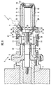
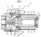
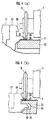
本発明の一実施形態を図面に基づいて説明する。図1は本実施形態のドラムの切断装置を示す説明的断面図、図2は大径ドラム用保持部材を支持した切断装置の要部の説明的断面図、図3はクランプ手段の作動を示す拡大説明図、図4は第1及び第2爪部と切刃との位置関係を示す拡大説明図である。 An embodiment of the present invention will be described with reference to the drawings. FIG. 1 is an explanatory cross-sectional view showing a drum cutting device according to the present embodiment, FIG. 2 is an explanatory cross-sectional view of a main part of the cutting device that supports a holding member for a large-diameter drum, and FIG. FIG. 4 is an enlarged explanatory view, and FIG. 4 is an enlarged explanatory view showing the positional relationship between the first and second claw portions and the cutting blade.
図1に示す本実施形態の切断装置1は、金属製の薄板により円筒状に形成されたドラムを所定幅毎に切断して複数の金属リングを形成するものである。なお、該ドラムは、周長の異なる金属リングを得るために、小径ドラム2(図1参照)と大径ドラム3(図2参照)とが用意される。 A cutting apparatus 1 according to this embodiment shown in FIG. 1 forms a plurality of metal rings by cutting a drum formed in a cylindrical shape by a thin metal plate into predetermined widths. The drum is prepared with a small-diameter drum 2 (see FIG. 1) and a large-diameter drum 3 (see FIG. 2) in order to obtain metal rings having different circumferential lengths.
先ず、本実施形態の切断装置1の構成を説明する。図1に示すように、切断装置1は、ドラム(小径ドラム2や大径ドラム3)を保持して回転させるドラム保持装置4と、該ドラム保持装置4に保持されたドラム(小径ドラム2や大径ドラム3)を輪切り状に切断する押切り刃具5とを備えている。該押切り刃具5は円盤状の切刃6を回転自在に備え、切刃6は切断時に図示しない刃具移動手段によってドラム(小径ドラム2や大径ドラム3)の軸線方向に移動されつつ所定寸法毎にドラム(小径ドラム2や大径ドラム3)に押し当てられる。
First, the structure of the cutting device 1 of this embodiment is demonstrated. As shown in FIG. 1, the cutting device 1 includes a drum holding device 4 that holds and rotates a drum (a small-
ドラム保持装置4は、図示しない回転駆動手段により回転される回転軸7と、該回転軸7に複数の連結部材8,9,10を介して連結された支持軸11とを備えている。支持軸11には、小径ドラム2を装着する円筒状の小径ドラム用保持部材12が着脱自在に支持される。なお、小径ドラム用保持部材12は、支持軸11の先端から装着された後、該支持軸11の先端にボルト13によって取り外し自在に設けられた固定部材14により支持軸11に固定される。
The drum holding device 4 includes a rotating shaft 7 that is rotated by a rotation driving unit (not shown), and a
また、支持軸11の基端部には、小径ドラム用保持部材12に保持された小径ドラム2をクランプするクランプ手段15が設けられている。該クランプ手段15は、枢軸16に揺動自在に支持された揺動部材17と、該揺動部材17の先端にボルト18によって連結された爪部材19とを備えている。
Further, a clamping means 15 for clamping the
該爪部材19は、小径ドラム用保持部材12に保持された小径ドラム2の一端部に圧接して小径ドラム2を固定する第1爪部20と、図2に示すように後述する大径ドラム用保持部材21に保持された大径ドラム3の一端部に圧接して大径ドラム3を固定する第2爪部22とを一体に備えている。第1爪部20は、第2爪部22よりも先端方向に延出されて設けられている。これにより、図1において仮想線示するように、切り込み時の押切り刃具5と第2爪部22との接触が回避される。
The
また、図1に示すように、前記揺動部材17は、バネ部材23により第1爪部20が小径ドラム2から離反する揺動方向に付勢されている。回転軸7及び支持軸11の内部には、その軸線方向に進退するドローバー24が設けられている。該ドローバー24の先端には、ボルト25を介して当接部材26が固定されており、前記揺動部材17には、当接部材26に当接すべく支持軸11の内部に向かって突出する当接部27が形成されている。ドローバー24は、図示しない進退駆動手段により進退駆動され、詳しくは後述するが、ドローバー24が後退したとき、当接部材26が揺動部材17の当接部27に当接して該揺動部材17を揺動させる。
As shown in FIG. 1, the
前記支持軸11は、図2に示すように、大径ドラム3を装着する円筒状の大径ドラム用保持部材21を着脱自在に支持することができる。大径ドラム用保持部材21は、小径ドラム用保持部材12と同様に、支持軸11の先端から装着された後、前記固定部材14により支持軸11に固定される。このとき、大径ドラム用保持部材21には、前記第1爪部20との干渉を回避するために、該第1爪部20を揺動可能な空隙を存して収容する収容部28が形成されている。
As shown in FIG. 2, the
支持軸11に大径ドラム用保持部材21を装着したときには、前記爪部材19の第2爪部22が大径ドラム3の一端部に圧接して大径ドラム3を固定する。このように、本実施形態の切断装置1によれば、小径ドラム用保持部材12と大径ドラム用保持部材21とを前記支持軸11に選択的に取り付けることができ、小径ドラム2と大径ドラム3との何れであっても容易に切断することができる。
When the large-diameter
次に、本実施形態の切断装置1によるドラムの切断作業を説明する。図1を参照すれば、先ず、支持軸11の先端から固定部材14を取り外して小径ドラム用保持部材12又は大径ドラム用保持部材21を支持軸11に装着し、固定部材14を取り付ける。小径ドラム用保持部材12を装着した場合には、次いで、図3(a)に示すように、ドローバー24を前進させて当接部材26による揺動部材17の当接部27への当接を解除する。これにより、揺動部材17はバネ部材23による付勢によって揺動し、第1爪部20が小径ドラム用保持部材12から離反する。そして、小径ドラム用保持部材12に小径ドラム2を装着し、図3(b)に示すように、ドローバー24を後退させる。これにより、当接部材26が揺動部材17の当接部27に当接して揺動部材17が揺動し、第1爪部20が小径ドラム2に圧接して小径ドラム2が小径ドラム用保持部材12に固定される。続いて、回転軸7の回転によって小径ドラム2が回転され、図1を参照すれば、押切り刃具5により、先端部から基端部方向に所定幅毎に小径ドラム2が切断される。
Next, the drum cutting operation by the cutting apparatus 1 of the present embodiment will be described. Referring to FIG. 1, first, the fixing
そして、図4(a)に示すように、押切り刃具5が第1爪部20の最も近接した位置に切り込むとき、第1爪部20が押切り刃具5と前記第2爪部22との接触を回避する位置に延出して設けられていることにより、押切り刃具5が前記第2爪部22に当たって切り込み動作が阻害されることなく、前記第1爪部20に極めて近接した位置で押切り刃具5による切断を行うことができる。なお、押切り刃具5の切刃6は所定の刃角に形成されているが、第1爪部20の先端壁に、切刃6の一側面に対応する傾斜面29を形成しておくことにより、切刃6を第1爪部20の極めて近い位置に切り込ませることができ、歩留まり良く複数の金属リングを形成することができる。
As shown in FIG. 4A, when the cutting blade 5 is cut into the closest position of the
また、小径ドラム用保持部材12に替えて大径ドラム用保持部材21を支持軸11に装着した場合には、図3(a)に仮想線で示すように、第2爪部22を大径ドラム用保持部材21から離反させて大径ドラム3を装着し、続いて、図3(b)に示すように、第2爪部22を大径ドラム3に圧接させて大径ドラム3を大径ドラム用保持部材21に固定する。このとき、大径ドラム用保持部材21は前記収容部28に第2爪部22を収容しているので、揺動部材17の揺動が円滑に行われる。次いで、回転軸7の回転によって大径ドラム3を回転させ、図2を参照すれば、押切り刃具5により、先端部から基端部方向に所定幅毎に大径ドラム3を切断する。
When the large-diameter
そして、図4(b)に示すように、第2爪部22の先端壁にも、切刃6の一側面に対応する傾斜面30を形成しておくことにより、切刃6を第2爪部22の極めて近い位置に切り込ませることができ、歩留まり良く複数の金属リングを形成することができる。
And as shown in FIG.4 (b), by forming the
1…切断装置、2…小径ドラム(ドラム)、3…大径ドラム、5…押切り刃具、6…切刃、11…支持軸、12…小径ドラム用保持部材(保持部材)、15…クランプ手段、17…揺動部材、20…第1爪部、21…大径ドラム用保持部材、22…第2爪部、28…収容部、29,30…傾斜面。 DESCRIPTION OF SYMBOLS 1 ... Cutting device, 2 ... Small diameter drum (drum), 3 ... Large diameter drum, 5 ... Pressing cutting tool, 6 ... Cutting blade, 11 ... Support shaft, 12 ... Holding member (holding member) for small diameter drums, 15 ... Clamp Means, 17 ... swinging member, 20 ... first claw portion, 21 ... holding member for large diameter drum, 22 ... second claw portion, 28 ... accommodating portion, 29, 30 ... inclined surface.
Claims (2)
前記ドラムを外周に保持する筒状の保持部材と、
該保持部材の内部に挿着することにより該保持部材を着脱自在に支持して回転駆動される支持軸と、
該支持軸に設けられ、前記保持部材に保持されたドラムの一端縁部をクランプして該ドラムを保持部材に固定するクランプ手段と、
該保持部材に保持されて回転されるドラムの外側から該ドラムに切り込んで該ドラムを輪切り状に切断する押切り刃具と、
該刃具をドラムの軸線方向に移動させつつ所定寸法毎にドラムに押し当てる刃具移動手段とを備え、
前記支持軸は、前記保持部材と前記ドラムより大径の大径ドラムを保持すべく該保持部材より外径が大とされた大径ドラム用保持部材とを選択的に支持可能とされており、
前記クランプ手段は、前記支持軸に前記保持部材を支持したときにドラムの一端縁部に圧接する第1爪部と、前記支持軸に前記大径ドラム用保持部材を支持したときに大径ドラムの一端縁部に圧接する第2爪部と、第1爪部と第2爪部とを一体に支持する揺動自在の揺動部材と、該揺動部材の揺動を駆動して両爪部を圧接方向に揺動させる揺動駆動手段とを備え、
前記第1爪部は、前記支持軸に前記保持部材を支持したときに切り込み時の押切り刃具と前記第2爪部との接触を回避する位置に延出して設けられ、
前記大径ドラム用保持部材には、前記支持軸に支持されたときに前記第1爪部を揺動可能な空隙を存して収容する収容部が形成されていることを特徴とする金属製薄板ドラムの切断装置。 A metal thin plate drum cutting device that forms a plurality of metal rings by cutting a drum formed into a cylindrical shape by a metal thin plate at a predetermined width,
A cylindrical holding member for holding the drum on the outer periphery;
A support shaft that is rotationally driven by removably supporting the holding member by being inserted into the holding member;
Clamping means provided on the support shaft and clamping one end edge of the drum held by the holding member to fix the drum to the holding member;
A cutting blade that cuts into the drum from the outside of the drum that is held and rotated by the holding member and cuts the drum into a ring shape;
A cutting tool moving means for pressing the cutting tool against the drum every predetermined dimension while moving the cutting tool in the axial direction of the drum,
The support shaft can selectively support the holding member and a large-diameter drum holding member having an outer diameter larger than that of the holding member so as to hold a large-diameter drum larger in diameter than the drum. ,
The clamp means includes a first claw portion that presses against one end edge of the drum when the holding member is supported on the support shaft, and a large-diameter drum that supports the large-diameter drum holding member on the support shaft. A second claw portion that presses against one edge of the first claw portion, a swingable swinging member that integrally supports the first claw portion and the second claw portion, and both claws by driving the swinging of the swinging member. Rocking drive means for rocking the part in the press-contact direction,
The first claw portion is provided to extend to a position that avoids contact between the pressing blade and the second claw portion at the time of cutting when the holding member is supported on the support shaft.
The large-diameter drum holding member is formed with a housing portion that houses a gap that can swing the first claw portion when supported by the support shaft. Thin drum cutting device.
前記第1爪部及び第2爪部は、該押切り刃具に対向する先端壁に、前記切刃の一側面に対応する傾斜面が形成されていることを特徴とする請求項1記載の金属製薄板ドラムの切断装置。 The pressing blade tool includes a cutting blade formed at a predetermined blade angle,
2. The metal according to claim 1, wherein the first claw portion and the second claw portion are formed with an inclined surface corresponding to one side surface of the cutting blade on a tip wall facing the pressing blade tool. Cutting device for thin plate drum.
Priority Applications (1)
| Application Number | Priority Date | Filing Date | Title |
|---|---|---|---|
| JP2004111860A JP4249648B2 (en) | 2004-04-06 | 2004-04-06 | Metal sheet drum cutting device |
Applications Claiming Priority (1)
| Application Number | Priority Date | Filing Date | Title |
|---|---|---|---|
| JP2004111860A JP4249648B2 (en) | 2004-04-06 | 2004-04-06 | Metal sheet drum cutting device |
Publications (2)
| Publication Number | Publication Date |
|---|---|
| JP2005297074A true JP2005297074A (en) | 2005-10-27 |
| JP4249648B2 JP4249648B2 (en) | 2009-04-02 |
Family
ID=35329245
Family Applications (1)
| Application Number | Title | Priority Date | Filing Date |
|---|---|---|---|
| JP2004111860A Expired - Fee Related JP4249648B2 (en) | 2004-04-06 | 2004-04-06 | Metal sheet drum cutting device |
Country Status (1)
| Country | Link |
|---|---|
| JP (1) | JP4249648B2 (en) |
Cited By (3)
| Publication number | Priority date | Publication date | Assignee | Title |
|---|---|---|---|---|
| CN101797664A (en) * | 2009-02-10 | 2010-08-11 | 本田技研工业株式会社 | Apparatus and method for cutting hollow cylindrical workpieces |
| DE102011004236A1 (en) | 2010-02-16 | 2011-08-18 | Honda Motor Co., Ltd., Tokyo | Cutting device for cylindrical workpiece for cutting hollow cylindrical workpiece of metal in several metal rings by laser beam, which is applied by laser beam source, comprises retaining element having side wall, and pressure element |
| DE102011004246A1 (en) | 2010-02-16 | 2011-08-18 | Honda Motor Co., Ltd. | Producing metal rings for cutting hollow cylindrical workpiece from metal by a laser beam, which is applied by a laser beam source into the metal rings, comprises using a side wall of holding element, and cutting the cylindrical workpiece |
-
2004
- 2004-04-06 JP JP2004111860A patent/JP4249648B2/en not_active Expired - Fee Related
Cited By (9)
| Publication number | Priority date | Publication date | Assignee | Title |
|---|---|---|---|---|
| CN101797664A (en) * | 2009-02-10 | 2010-08-11 | 本田技研工业株式会社 | Apparatus and method for cutting hollow cylindrical workpieces |
| EP2216127A1 (en) | 2009-02-10 | 2010-08-11 | Honda Motor Co., Ltd. | Apparatus and method for cutting hollow cylindrical workpiece with a chilled/cooled rotatable workpiece holder |
| US8487207B2 (en) | 2009-02-10 | 2013-07-16 | Honda Motor Co., Ltd. | Apparatus and method for cutting hollow cylindrical workpiece |
| DE102011004236A1 (en) | 2010-02-16 | 2011-08-18 | Honda Motor Co., Ltd., Tokyo | Cutting device for cylindrical workpiece for cutting hollow cylindrical workpiece of metal in several metal rings by laser beam, which is applied by laser beam source, comprises retaining element having side wall, and pressure element |
| DE102011004246A1 (en) | 2010-02-16 | 2011-08-18 | Honda Motor Co., Ltd. | Producing metal rings for cutting hollow cylindrical workpiece from metal by a laser beam, which is applied by a laser beam source into the metal rings, comprises using a side wall of holding element, and cutting the cylindrical workpiece |
| CN102161132A (en) * | 2010-02-16 | 2011-08-24 | 本田技研工业株式会社 | Manufacture method for metal rings |
| CN102161133A (en) * | 2010-02-16 | 2011-08-24 | 本田技研工业株式会社 | Cutting device for cylindrical workpiece |
| DE102011004246B4 (en) * | 2010-02-16 | 2012-09-06 | Honda Motor Co., Ltd. | Manufacturing method of a metal ring and use of the metal ring |
| DE102011004236B4 (en) * | 2010-02-16 | 2013-04-11 | Honda Motor Co., Ltd. | Cutting device for a cylindrical workpiece |
Also Published As
| Publication number | Publication date |
|---|---|
| JP4249648B2 (en) | 2009-04-02 |
Similar Documents
| Publication | Publication Date | Title |
|---|---|---|
| JP2011235298A (en) | Tube expander | |
| JP4249648B2 (en) | Metal sheet drum cutting device | |
| JP2014083635A (en) | Pipe cutter | |
| JP2010214449A (en) | Plastic working apparatus and plastic working method | |
| JP4826178B2 (en) | Cutting apparatus and cutting method | |
| JP2020066043A (en) | Shaft thickening metal mold, shaft thickening device, stepped shaft manufacturing method and stepped shaft | |
| JPH0940234A (en) | Sheet winder and its bobbin chucking device | |
| JP4892327B2 (en) | Tube cutting apparatus and tube cutting method | |
| JP2004304954A (en) | Method and device for cutting wire of armature | |
| JP3338008B2 (en) | Supporting device for ultrasonic vibration resonator | |
| JP4739853B2 (en) | Sheet cutting device and cutting method | |
| JP5701093B2 (en) | Tube cutting method and tube cutting device | |
| JP3146237U (en) | Rotating tool mounting shaft and rotating tool equipped with the mounting shaft | |
| JP2003103404A (en) | Rolling center with center drill | |
| JP2001353612A (en) | Metal thin-plate drum cutting apparatus and cutting method | |
| JP2005095996A (en) | Chuck device | |
| JP2004291048A (en) | Spinning molding machine | |
| JP3833210B2 (en) | Bead wire winding device | |
| JP2015020236A (en) | Tube cutting device | |
| JP2005254364A (en) | Electric drilling device | |
| JP4539411B2 (en) | Caulking device | |
| JP4763304B2 (en) | Method and apparatus for cutting tubular member | |
| JPH0232334Y2 (en) | ||
| JP4173828B2 (en) | Metal sheet drum cutting device | |
| JPH0410975Y2 (en) |
Legal Events
| Date | Code | Title | Description |
|---|---|---|---|
| A621 | Written request for application examination |
Effective date: 20061130 Free format text: JAPANESE INTERMEDIATE CODE: A621 |
|
| A977 | Report on retrieval |
Effective date: 20080930 Free format text: JAPANESE INTERMEDIATE CODE: A971007 |
|
| TRDD | Decision of grant or rejection written | ||
| A01 | Written decision to grant a patent or to grant a registration (utility model) |
Free format text: JAPANESE INTERMEDIATE CODE: A01 Effective date: 20090113 |
|
| A01 | Written decision to grant a patent or to grant a registration (utility model) |
Free format text: JAPANESE INTERMEDIATE CODE: A01 |
|
| A61 | First payment of annual fees (during grant procedure) |
Effective date: 20090115 Free format text: JAPANESE INTERMEDIATE CODE: A61 |
|
| FPAY | Renewal fee payment (prs date is renewal date of database) |
Free format text: PAYMENT UNTIL: 20120123 Year of fee payment: 3 |
|
| R150 | Certificate of patent (=grant) or registration of utility model |
Free format text: JAPANESE INTERMEDIATE CODE: R150 |
|
| LAPS | Cancellation because of no payment of annual fees |