JP2005297055A - Ultrasonic bonding horn - Google Patents
Ultrasonic bonding horn Download PDFInfo
- Publication number
- JP2005297055A JP2005297055A JP2004121130A JP2004121130A JP2005297055A JP 2005297055 A JP2005297055 A JP 2005297055A JP 2004121130 A JP2004121130 A JP 2004121130A JP 2004121130 A JP2004121130 A JP 2004121130A JP 2005297055 A JP2005297055 A JP 2005297055A
- Authority
- JP
- Japan
- Prior art keywords
- convex
- wire
- ultrasonic bonding
- ultrasonic
- vibration
- Prior art date
- Legal status (The legal status is an assumption and is not a legal conclusion. Google has not performed a legal analysis and makes no representation as to the accuracy of the status listed.)
- Pending
Links
Images

Landscapes
- Pressure Welding/Diffusion-Bonding (AREA)
Abstract
【課題】 細い素線を使用した電線でも超音波接合時に電線の損傷が発生し難く、かつ信頼性のより高い接合部を得ることができる超音波接合ホーンを提供すること。
【解決手段】 電線を被接合部材に押圧しつつ当該電線にその軸方向の超音波振動を加える接合ブロックを先端部に備え、当該接合ブロックの前記電線との接触面は多数の凸部を有する凹凸面を形成し、前記振動方向である前記凹凸面の長さ方向の少なくとも一端部は断面が円弧状部に形成されていることを最も主要な特徴とする。凹凸面の凸部の一部が当該凹凸面の端部に位置するように構成し、当該凸部に円弧状部を形成するのが好ましい。
【選択図】 図2PROBLEM TO BE SOLVED: To provide an ultrasonic bonding horn capable of obtaining a highly reliable bonding portion in which an electric wire using a thin element wire is not easily damaged during ultrasonic bonding.
A tip is provided with a joining block that applies ultrasonic vibration in the axial direction to the wire while pressing the wire against a member to be joined, and the contact surface of the joining block with the wire has a number of convex portions. The most main feature is that an uneven surface is formed, and at least one end portion in the length direction of the uneven surface, which is the vibration direction, is formed in a circular arc cross section. It is preferable that a part of the convex portion of the concave and convex surface is configured to be located at an end portion of the concave and convex surface, and an arc-shaped portion is formed on the convex portion.
[Selection] Figure 2
Description
本発明は超音波接合ホーンに関し、さらに詳しくは、撚線導体と被接合部材(端子板)とを超音波加振により接合する超音波接合ホーンの構造に関するものである。 The present invention relates to an ultrasonic bonding horn, and more particularly to a structure of an ultrasonic bonding horn that bonds a stranded conductor and a member to be bonded (terminal plate) by ultrasonic vibration.
例えば自動車のワイヤーハーネスを製造するには、電線と端子とを電気的に接続する必要がある。このような電線と端子との接合には、接続の信頼性を高めるため多くの場合超音波接合法が用いられる。
電線と被接合部材との超音波接合では、水平に支持された被接合部材の上に接合部の絶縁被覆を除いた電線の端末を載置し、その上から接合ホーン先端の接合ブロックで押圧しつつ電線の軸方向に超音波振動を加える。この接合ブロックの押圧と超音波加振により、被接合材と電線の表面の酸化被膜等が除去され、電線と被接合材とが溶着する。
For example, in order to manufacture an automobile wire harness, it is necessary to electrically connect an electric wire and a terminal. For joining such electric wires and terminals, an ultrasonic joining method is often used in order to improve connection reliability.
In ultrasonic bonding between an electric wire and a member to be joined, the end of the electric wire excluding the insulation coating of the joining portion is placed on the member to be joined that is horizontally supported, and then pressed by the joining block at the tip of the joining horn. While applying ultrasonic vibration in the axial direction of the wire. By this pressing of the joining block and ultrasonic vibration, an oxide film or the like on the surface of the material to be joined and the wire is removed, and the wire and the material to be joined are welded.
ところで、接合ブロックの先端面(電線との接触面)は滑り止めのために多数の凸部を形成した凹凸面であり、凸部は角部を有するため、電線の接合部分の加振方向前端と後端に傷(素線の切断等)が付き機械的強度が低下する。
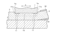
この課題を解決するため、例えば図5で示すように、接合ホーン先端部における接合ブロック1の凹凸面10の加振方向(振動方向)aの少なくとも一端部に、凸部を有しない平滑面部(又はテーパ面部)10aを形成した超音波接合ホーンが提案されている(後記特許文献1)。
前記超音波ホーンによれば、水平に支持された被接合部材2の上に接合部の絶縁被覆30を削除した電線3を置き、超音波接合ホーンの接合ブロック1の凹凸面10により電線3を被接合部材2に押圧しつつ矢印a方向(電線の軸方向)に超音波振動を加えた際、平滑面部(テーパ面部)10aと電線3との摺動が可能(円滑)になるため、電線の損傷を防止することができるものとされている。
In order to solve this problem, for example, as shown in FIG. 5, a smooth surface portion having no convex portion (at least one end portion in the vibration direction (vibration direction) a of the
According to the ultrasonic horn, the
しかしながら、図5の接合ブロック1の平滑面部(テーパ面部)10aにおいても、電線3に超音波振動を印加すると電線3の素線同士も接合し、接合部における素線間の隙間が減少して電線3の非接合部よりも接合部の外径(図5における上下方向の量)が小さくなる。すなわち同図のように、接合ブロック1の凹凸面10の平滑面部(テーパ面部)10aと、接合ブロック1の振動方向の端部の面(多くは垂直面)1aとの交差部がエッジ状を呈するので、電線3に損傷が発生し易く、かつ、平滑面部(テーパ面部)10aの長さLを長くすると接合強度が低下する。この傾向は、芯線の素線径が0.5mm以下のように細い場合に顕著になる。
However, even in the smooth surface portion (tapered surface portion) 10a of the joining
本発明は、細い素線を使用した電線でも超音波接合時に電線の損傷が発生し難く、かつ信頼性のより高い接合部を得ることができる超音波接合ホーンを提供することをその課題としている。 It is an object of the present invention to provide an ultrasonic bonding horn that is less likely to cause damage to an electric wire even when the electric wire uses a thin element wire and can obtain a highly reliable bonding portion. .
本発明に係る超音波接合ホーンは、前述の課題を解決するため、電線を被接合部材に押圧しつつ当該電線にその軸方向の超音波振動を加える接合ブロックを先端部に備え、当該接合ブロックの前記電線との接触面は多数の凸部を有する凹凸面を形成し、前記振動方向である前記凹凸面の長さ方向の少なくとも一端部は断面が円弧状部に形成されていることを最も主要な特徴としている。凹凸面の凸部の一部が当該凹凸面の端部に位置するように構成し、当該凸部に円弧状部を形成するのが好ましい。 In order to solve the above-described problem, an ultrasonic bonding horn according to the present invention includes a bonding block that applies ultrasonic vibration in an axial direction to an electric wire while pressing the electric wire against a member to be bonded. The contact surface with the electric wire forms a concavo-convex surface having a large number of convex portions, and at least one end portion in the length direction of the concavo-convex surface, which is the vibration direction, has a cross section formed in an arc-shaped portion. Main features. It is preferable that a part of the convex portion of the concave and convex surface is configured to be located at an end portion of the concave and convex surface, and an arc-shaped portion is formed on the convex portion.
本発明に係る超音波接合ホーンは、接合ブロックの電線との接触面である凹凸面の超音波接合時における振動方向の一端部又は両端部を断面円弧状に形成したので、当該端部がエッジ状を呈せず、凹凸面により電線を被接合部材に押圧して超音波振動させた場合に、電線の損傷を防止しつつ信頼性の高い接合部を得ることができる。 In the ultrasonic bonding horn according to the present invention, since one end or both ends in the vibration direction at the time of ultrasonic bonding of the uneven surface which is a contact surface with the electric wire of the bonding block is formed in a circular arc shape, the end is an edge. When the wire is pressed against the member to be joined by the concavo-convex surface and subjected to ultrasonic vibration, a highly reliable joint can be obtained while preventing damage to the wire.
以下、本発明に係る超音波接合ホーン図示の実施形態に基づいて説明する。
第1実施形態
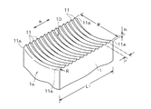
図1は本発明に係る超音波接合ホーンの第1実施形態を示す逆さ状態の部分斜視図、図2は図1の形態の超音波接合ホーンを使用して被接合部材と電線とを接合する状態を示す部分断面図である。
Hereinafter, the ultrasonic bonding horn according to the present invention will be described based on the illustrated embodiments.
First Embodiment FIG. 1 is an inverted partial perspective view showing a first embodiment of an ultrasonic bonding horn according to the present invention, and FIG. 2 shows a member to be bonded and an electric wire using the ultrasonic bonding horn of the embodiment shown in FIG. It is a fragmentary sectional view which shows the state which joins.
超音波接合ホーンは、図示しない振動軸を振動させる振動発生部を備え、振動軸の先端部には図1に示すような接合ブロック1が設けられている。この接合ブロック1はほぼ直方体形状の金属ブロックであり、接合する電線(絶縁被覆30を除いた電線)3の径よりも幅が広く設定されている。
接合ブロック1の電線3との接触面は、電線の滑り止めのために多数の凸部11を形成した凹凸面10となっている。各凸部11は、使用時の超音波による振動方向(接合ブロック1の長さ方向)aと交差する方向(接合ブロック1の幅方向)に沿って連続する断面三角形状の凸部である。凹凸面10は、使用時に裸の電線3を抱く状態で押えるのに適するように、接合ブロック1の幅方向へ凹円弧状を呈すべく加工されている。すなわち凹凸面10は、全体として接合ブロック1の長さ方向に沿う凹円弧状の溝に形成されている。
The ultrasonic bonding horn includes a vibration generating unit that vibrates a vibration shaft (not shown), and a
The contact surface of the joining
凹凸面10の長さ方向の一端部または両端部は、断面が円弧状部11aに形成されていて、当該凹凸面10と接合ブロック1の振動方向の端部の面1aとはエッジを形成しないように構成されている。
この実施形態では、凹凸面10の全面にわたるように断面三角形状の凸部11を一定のピッチで形成し、当該凹凸面10の振動方向両端部に位置する各凸部11の外側を面取り加工して円弧状部11aに形成している。
One end portion or both end portions of the
In this embodiment, the
接合ブロック1の寸法は、絶縁被覆30を削除した電線(撚線)3の大きさや素線の径等により適切に設定されるが、この実施形態における各部の寸法は次の範囲である。
長さL1=10〜20mm,幅W=7〜14mm(裸の電線の直径よりも大きい),凹凸面の凹円弧状の半径=8〜20mm,11のピッチP=0.5〜2.0mm,凸部11の高さh=0.1〜1.5mm。 円弧状部11aは、その曲率半径R=0.3〜1.5mmに加工されているのが好ましい。前記曲率半径Rが0.3mm未満であると、凹凸面10の端部で電線3が損傷し易くなり、前記曲率半径Rが1.5mmを超えると、電線の損傷は防止できるが、凹凸面10における凸部形成領域の面積が減少することにより電線と被接合部材の接合強度が低下するおそれがある。
The dimensions of the joining
Length L1 = 10 to 20 mm, width W = 7 to 14 mm (larger than the diameter of the bare wire), concave arc-shaped radius of uneven surface = 8 to 20 mm, 11 pitch P = 0.5 to 2.0 mm , Height h of the
前記実施形態の超音波接合ホーンを用いて、電線3の絶縁被覆30を剥離した接合部(端部)を金属板からなる被接合部材2と接合するには、図2で示すように、水平に支持された被接合部材2の上に裸の電線3を載置し、超音波接合ホーンの接合ブロック1の凹凸面10により電線3を被接合部材2へ押圧し、この状態で図示しない振動発生部を駆動させて接合ブロック1を矢印aの方向に振動させる。
前記押圧と振動とにより、接合ブロックが裸の電線に食い込んだ状態で振動し、電線と被接合部材は、金属相互の摩擦により表面の酸化皮膜等が除去され、摩擦熱によって溶着される。
凹凸面10における長さ方向の端部の断面は、当該端部に位置する凸部11の外側が断面円弧状に加工することにより円弧状部11aに形成されており、凹凸面10と接合ブロク1の振動方向の端部の面1aとの交差部が角になっていないため、押圧と超音波振動とにより電線3が損傷するのを防止することができる。また、凹凸面10には平滑面やテーパ面を形成せず、その全面に凸部11を形成することができるから接合強度が十分に保たれ、接合の信頼性を確保することができる。
In order to join the joining part (end part) from which the insulation coating 30 of the
Due to the pressing and vibration, the joining block vibrates in a state where the joining block bites into the bare electric wire, and the surface of the electric wire and the member to be joined are removed by friction between metals and welded by frictional heat.
The cross-section of the end portion in the length direction of the
第2実施形態
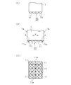
図3は本発明に係る超音波接合ホーンの第2実施形態を示す図で、(A)図は部分正面図、(B)図は部分側面図、(C)図は底面図である。
この実施形態において、接合ブロック1の凹凸面10には、四角錘状(又は四角錘台形状)の多数の細い凸部11が縦横に整列するように形成され、凹凸面10の長さ方向(使用時における振動方向a)の端部における各凸部11の外側は断面が円弧状部11aに形成されている。
凹凸面10は全体として平らに形成されているが、第1実施形態と同様に幅方向に沿って凹円弧状に形成されていても差し支えない。
この実施形態の著音波接合ホーンの他の構成や作用効果は、第1実施形態のものとほぼ同様であるのでそれらの説明は省略する。
Second Embodiment FIG. 3 is a view showing a second embodiment of the ultrasonic bonding horn according to the present invention, wherein (A) is a partial front view, (B) is a partial side view, and (C) is a bottom view. It is.
In this embodiment, the concave and
Although the concavo-
The other configurations and operational effects of the sonic bonding horn of this embodiment are substantially the same as those of the first embodiment, so that the description thereof is omitted.
第3実施形態
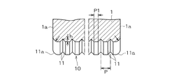
図4は本発明に係る超音波接合ホーンの第3実施形態を示す部分断面図である。
この実施形態の超音波接合ホーンにおいて、接合ブロック1の凸部11は凹凸面10の幅方向に沿って連続し、一定のピッチPで長さ方向に密に並ぶ状態に形成されている。凸部11の断面形状は台形状であり、頂部に一定の幅P1の面取り部を形成している。凹凸面10は幅方向に凹円弧状を呈しており、凹凸面10における長さ方向の端部の凸部11は、その外側が断面円弧状部11aに形成されている。
この実施形態の超音波接合ホーンは、接合ブロック1の凸部11が断面台形形状であるので、接合時の電線の損傷がさらによく防止される。
この実施形態の超音波接合ホーンの他の構成や作用効果は、第1実施形態のものとほぼ同様であるのでそれらの説明は省略する。
Third Embodiment FIG. 4 is a partial cross-sectional view showing a third embodiment of the ultrasonic bonding horn according to the present invention.
In the ultrasonic bonding horn of this embodiment, the
In the ultrasonic bonding horn of this embodiment, since the
Since other configurations and operational effects of the ultrasonic bonding horn of this embodiment are substantially the same as those of the first embodiment, their description is omitted.
図1及び図4の形態の超音波接合ホーンにおいては、凹凸面10を幅方向に沿って凹円弧状を呈するように形成するのに代えて、凹凸面10を全体として平らに形成することができる。
In the ultrasonic bonding horn shown in FIGS. 1 and 4, the
長さL1=14mm,幅W=10mm,凹凸面10の幅方向の凹円弧状の半径=8mm,凹凸面10の幅方向に連続する断面台形形状の凸部11のピッチP=1.0mm,凸部高さh=0.3mm,凸部11の頂部の面取り部幅P1=0.4mmの同じ材質の接合ブロック1を有する10種の超音波接合ホーンを試作した。
それらの超音波ホーンは、表1のように、両端部の凸部11の円弧状部11aの曲率半径Rが0〜1.6mmの範囲でそれぞれ異なるもの6種(実施例1,2,3及び比較例1,2,3)、凹凸面の一端部分にそれぞれ異なる長さLの平滑面部又はテーパ面部を有する4種(比較例4〜7)であった。
以上の各超音波接合ホーンと、接合部の絶縁被覆を削除した電線(断面積25mm2、0.32mmφの素線323本の撚線)を用いてそれぞれ同じ接合条件で超音波接合試験を行った。そして、各超音波接合サンプルについて、芯線損傷の有無を検査するとともに、金属板と電線が剥離するときの荷重を測定することにより引張強度を調べた。それらの結果を表1に併せて示す。
Length L1 = 14 mm, width W = 10 mm, concave arc-shaped radius in the width direction of the
As shown in Table 1, these ultrasonic horns are different from each other in the range where the radius of curvature R of the arc-
Using each of the above ultrasonic bonding horns and an electric wire from which the insulation coating of the bonding portion has been removed (a 323 strand of strands having a cross-sectional area of 25 mm 2 and 0.32 mmφ), an ultrasonic bonding test was performed under the same bonding conditions. It was. And about each ultrasonic joining sample, while checking the presence or absence of core wire damage, the tensile strength was investigated by measuring the load when a metal plate and an electric wire peel. The results are also shown in Table 1.
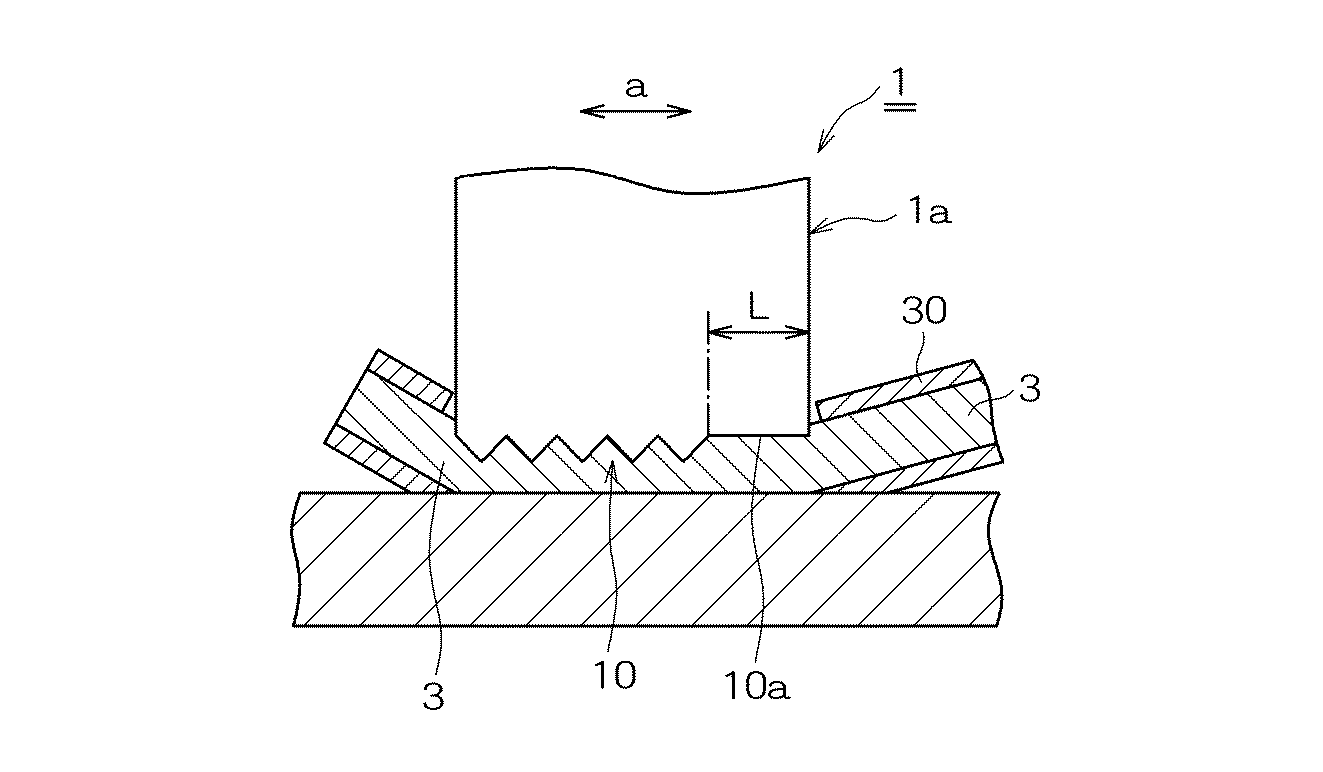
表1から明らかなように、実施例の超音波接合ホーンを用いて接合したものは優れた引張強度を示し、芯線の損傷は皆無であった。
これに対して、比較例1は円弧状部11aの曲率半径Rが小さ過ぎるためホーン端部において芯線損傷が発生した。比較例2は円弧状部11aの曲率半径が大きく、振動を伝える凹部数が減少したことにより引張強度が劣った。凹凸面10の一端部に平滑面部またはテーパ面部を形成した比較例3〜7では、いずれも端部に円弧状部がないため芯線損傷が発生したほか、凹凸面の凸部数が減少したことにより引張強度が劣った。
As is apparent from Table 1, those bonded using the ultrasonic bonding horn of the example showed excellent tensile strength, and the core wire was not damaged at all.
In contrast, in Comparative Example 1, the radius of curvature R of the arc-shaped
なお、比較例4〜7の凹凸面の構造であって凸部数の減少分だけ凹凸面の長さを長くして凸部数を増加したホーンを使用すると、引張強度は十分であるが凹凸面の長さが長くなり、接合に必要な芯線長さも長くなる。
以上第1〜第3の実施形態について説明したが、本発明はこれらの実施形態に限定されるものではなく、構成の要旨に付随する各種の変更が可能である。
In addition, when the horn having the uneven surface structure of Comparative Examples 4 to 7 and having the uneven surface length increased by the decrease in the number of convex portions to increase the number of convex portions, the tensile strength is sufficient, but the uneven surface The length is increased, and the length of the core wire necessary for joining is also increased.
Although the first to third embodiments have been described above, the present invention is not limited to these embodiments, and various modifications accompanying the gist of the configuration are possible.
1 接合ブロック
1a 振動方向の端部の面
10 凹凸面
11 凸部
11a 円弧状部
2 被接合部材
3 電線
30 絶縁被覆
a 振動方向
R 曲率半径
DESCRIPTION OF
Claims (5)
Priority Applications (1)
| Application Number | Priority Date | Filing Date | Title |
|---|---|---|---|
| JP2004121130A JP2005297055A (en) | 2004-04-16 | 2004-04-16 | Ultrasonic bonding horn |
Applications Claiming Priority (1)
| Application Number | Priority Date | Filing Date | Title |
|---|---|---|---|
| JP2004121130A JP2005297055A (en) | 2004-04-16 | 2004-04-16 | Ultrasonic bonding horn |
Publications (1)
| Publication Number | Publication Date |
|---|---|
| JP2005297055A true JP2005297055A (en) | 2005-10-27 |
Family
ID=35329232
Family Applications (1)
| Application Number | Title | Priority Date | Filing Date |
|---|---|---|---|
| JP2004121130A Pending JP2005297055A (en) | 2004-04-16 | 2004-04-16 | Ultrasonic bonding horn |
Country Status (1)
| Country | Link |
|---|---|
| JP (1) | JP2005297055A (en) |
Cited By (7)
| Publication number | Priority date | Publication date | Assignee | Title |
|---|---|---|---|---|
| JP2009241120A (en) * | 2008-03-31 | 2009-10-22 | Calsonic Kansei Corp | Ultrasonic metal bonding machine, metal sheet bonding method using the same, and bonded metal sheet obtained by using the ultrasonic metal bonding machine or the metal sheet bonding method |
| US7875138B2 (en) | 2007-10-03 | 2011-01-25 | Panasonic Corporation | Adhesive tape applying apparatus and tape splicing method |
| JP2012148325A (en) * | 2011-01-20 | 2012-08-09 | Nissan Motor Co Ltd | Ultrasonic joining apparatus |
| KR20170102350A (en) | 2015-02-27 | 2017-09-08 | 데쿠세리아루즈 가부시키가이샤 | Reel, film connecting body, film winding mounting body and manufacturing method of film connecting body |
| JP2018157082A (en) * | 2017-03-17 | 2018-10-04 | セイコーインスツル株式会社 | Electronic device and method of manufacturing the same |
| KR20190025652A (en) | 2016-08-04 | 2019-03-11 | 도시바 미쓰비시덴키 산교시스템 가부시키가이샤 | Ultrasonic bonding tool and ultrasonic bonding apparatus |
| CN111822842A (en) * | 2020-07-14 | 2020-10-27 | 中车株洲电机有限公司 | Ultrasonic welding method |
Citations (2)
| Publication number | Priority date | Publication date | Assignee | Title |
|---|---|---|---|---|
| JP2003334669A (en) * | 2002-05-17 | 2003-11-25 | Yazaki Corp | Ultrasonic welding equipment |
| JP2004114136A (en) * | 2002-09-27 | 2004-04-15 | Sony Corp | Ultrasonic welding equipment |
-
2004
- 2004-04-16 JP JP2004121130A patent/JP2005297055A/en active Pending
Patent Citations (2)
| Publication number | Priority date | Publication date | Assignee | Title |
|---|---|---|---|---|
| JP2003334669A (en) * | 2002-05-17 | 2003-11-25 | Yazaki Corp | Ultrasonic welding equipment |
| JP2004114136A (en) * | 2002-09-27 | 2004-04-15 | Sony Corp | Ultrasonic welding equipment |
Cited By (11)
| Publication number | Priority date | Publication date | Assignee | Title |
|---|---|---|---|---|
| US7875138B2 (en) | 2007-10-03 | 2011-01-25 | Panasonic Corporation | Adhesive tape applying apparatus and tape splicing method |
| CN101815663B (en) * | 2007-10-03 | 2012-06-13 | 松下电器产业株式会社 | Adhesive tape sticking device and tape connecting method |
| JP2009241120A (en) * | 2008-03-31 | 2009-10-22 | Calsonic Kansei Corp | Ultrasonic metal bonding machine, metal sheet bonding method using the same, and bonded metal sheet obtained by using the ultrasonic metal bonding machine or the metal sheet bonding method |
| JP2012148325A (en) * | 2011-01-20 | 2012-08-09 | Nissan Motor Co Ltd | Ultrasonic joining apparatus |
| KR20170102350A (en) | 2015-02-27 | 2017-09-08 | 데쿠세리아루즈 가부시키가이샤 | Reel, film connecting body, film winding mounting body and manufacturing method of film connecting body |
| KR20190035956A (en) | 2015-02-27 | 2019-04-03 | 데쿠세리아루즈 가부시키가이샤 | Reel body, film connection body, film winding body, and manufacturing method for film connection body |
| KR20190025652A (en) | 2016-08-04 | 2019-03-11 | 도시바 미쓰비시덴키 산교시스템 가부시키가이샤 | Ultrasonic bonding tool and ultrasonic bonding apparatus |
| DE112016007117T5 (en) | 2016-08-04 | 2019-04-25 | Toshiba Mitsubishi-Electric Industrial Systems Corporation | Ultrasonic welding tool and ultrasonic welding machine |
| US10946475B2 (en) | 2016-08-04 | 2021-03-16 | Toshiba Mitsubishi-Electric Industrial Systems Corporation | Tool for ultrasonic bonding and apparatus for ultrasonic bonding |
| JP2018157082A (en) * | 2017-03-17 | 2018-10-04 | セイコーインスツル株式会社 | Electronic device and method of manufacturing the same |
| CN111822842A (en) * | 2020-07-14 | 2020-10-27 | 中车株洲电机有限公司 | Ultrasonic welding method |
Similar Documents
| Publication | Publication Date | Title |
|---|---|---|
| JP5660458B2 (en) | Electric wire with terminal and manufacturing method thereof | |
| CN103299493B (en) | Connection method of wire and stranded wire and stator of electric motor or generator | |
| JP2013004406A (en) | Manufacturing method of wire with terminal | |
| JP6574795B2 (en) | Manufacturing method of electric wire with terminal | |
| JP2003338328A (en) | Welding terminal and its welding equipment | |
| JP2020013633A (en) | Wire with terminal and method of manufacturing the same | |
| JP2019096572A (en) | Manufacturing method of terminal-equipped electric wire and terminal-equipped electric wire | |
| US20190273327A1 (en) | Electric wire with terminal and method of manufacturing electric wire with terminal | |
| JP2019096568A (en) | Terminal-equipped electric wire and manufacturing method of terminal-equipped electric wire | |
| JP5191923B2 (en) | Wire connection method | |
| CN110021827A (en) | Attaching have the electric wire of terminal, attaching have terminal electric wire manufacturing method and electric wire | |
| WO2017154613A1 (en) | Method for manufacturing cable with terminal, and cable with terminal | |
| JP2025074603A (en) | Horn and ultrasonic bonding equipment | |
| JP2011014438A (en) | Electric wire connection structure, and conductive line for vehicle having the same | |
| JP3147749B2 (en) | Ultrasonic welding method | |
| JP2005297055A (en) | Ultrasonic bonding horn | |
| CN104218424A (en) | Electric wire connecting method and connecting device thereof | |
| JP2006024523A (en) | Connection terminal, ultrasonic connection device, method and connection part | |
| JP2000301357A (en) | Ultrasonic welding horn and wire terminal joining method | |
| JP2011134515A (en) | Electric wire with terminal fitting, and manufacturing method thereof | |
| JP6128946B2 (en) | Electric wire and terminal joining structure and joining method | |
| JP5041537B2 (en) | Connection structure of crimp terminal to covered wire | |
| JP2011258468A (en) | Terminal, electric wire with terminal and method for producing the same | |
| JP5223798B2 (en) | Electric wire connection structure and vehicle conductive path having the electric wire connection structure | |
| JP4731396B2 (en) | Terminal and aluminum wire with terminal |
Legal Events
| Date | Code | Title | Description |
|---|---|---|---|
| A621 | Written request for application examination |
Free format text: JAPANESE INTERMEDIATE CODE: A621 Effective date: 20070329 |
|
| RD02 | Notification of acceptance of power of attorney |
Free format text: JAPANESE INTERMEDIATE CODE: A7422 Effective date: 20090210 |
|
| A521 | Written amendment |
Free format text: JAPANESE INTERMEDIATE CODE: A821 Effective date: 20090213 |
|
| A521 | Written amendment |
Free format text: JAPANESE INTERMEDIATE CODE: A821 Effective date: 20090213 |
|
| RD04 | Notification of resignation of power of attorney |
Free format text: JAPANESE INTERMEDIATE CODE: A7424 Effective date: 20090319 |
|
| A977 | Report on retrieval |
Free format text: JAPANESE INTERMEDIATE CODE: A971007 Effective date: 20091023 |
|
| A131 | Notification of reasons for refusal |
Free format text: JAPANESE INTERMEDIATE CODE: A131 Effective date: 20091117 |
|
| A521 | Written amendment |
Free format text: JAPANESE INTERMEDIATE CODE: A523 Effective date: 20100118 |
|
| A02 | Decision of refusal |
Free format text: JAPANESE INTERMEDIATE CODE: A02 Effective date: 20100223 |
|
| A521 | Written amendment |
Free format text: JAPANESE INTERMEDIATE CODE: A523 Effective date: 20100524 |
|
| A911 | Transfer to examiner for re-examination before appeal (zenchi) |
Free format text: JAPANESE INTERMEDIATE CODE: A911 Effective date: 20100531 |
|
| A912 | Re-examination (zenchi) completed and case transferred to appeal board |
Free format text: JAPANESE INTERMEDIATE CODE: A912 Effective date: 20100625 |
|
| A521 | Written amendment |
Free format text: JAPANESE INTERMEDIATE CODE: A523 Effective date: 20110627 |