JP2005297047A - Brazing composite material and brazing product using the same - Google Patents
Brazing composite material and brazing product using the same Download PDFInfo
- Publication number
- JP2005297047A JP2005297047A JP2004120392A JP2004120392A JP2005297047A JP 2005297047 A JP2005297047 A JP 2005297047A JP 2004120392 A JP2004120392 A JP 2004120392A JP 2004120392 A JP2004120392 A JP 2004120392A JP 2005297047 A JP2005297047 A JP 2005297047A
- Authority
- JP
- Japan
- Prior art keywords
- brazing
- layer
- composite material
- thickness
- brazed
- Prior art date
- Legal status (The legal status is an assumption and is not a legal conclusion. Google has not performed a legal analysis and makes no representation as to the accuracy of the status listed.)
- Pending
Links
Images

Landscapes
- Fuel Cell (AREA)
Abstract
【課題】 焼鈍処理時に脆い金属間化合物の層が生成されるおそれがなく、かつ、被ろう付け材が侵食されるおそれが殆どないろう付け用複合材及びそれを用いたろう付け製品を提供するものである。
【解決手段】 本発明に係るろう付け用複合材10は、被ろう付け部材とろう付けされるものであり、ろう付け層15が、Ti又はTi合金層13、Ni又はNi合金層12、Fe又はFe合金層14の少なくとも3層の積層体で構成され、かつ、Ti又はTi合金層13とFe又はFe合金層14との間に、TiとFeとが反応して脆い金属間化合物が生成されるのを抑制する反応防止層としてNi又はNi合金層12bを配置したものである。
【選択図】 図1
PROBLEM TO BE SOLVED: To provide a brazing composite material and a brazing product using the same, in which there is no possibility that a brittle intermetallic compound layer is generated during annealing treatment and the brazing material is hardly corroded. It is.
A brazing composite material 10 according to the present invention is brazed to a member to be brazed, and a brazing layer 15 includes a Ti or Ti alloy layer 13, a Ni or Ni alloy layer 12, and a Fe. Or, it is composed of a laminate of at least three layers of the Fe alloy layer 14, and between the Ti or Ti alloy layer 13 and the Fe or Fe alloy layer 14, Ti and Fe react to produce a brittle intermetallic compound. The Ni or Ni alloy layer 12b is disposed as a reaction preventing layer that suppresses this.
[Selection] Figure 1
Description
本発明は、ろう付け用複合材及びそれを用いたろう付け製品に係り、特に、熱交換器や燃料電池用部材などの被ろう付け部材をろう付けするろう付け用複合材に関するものである。 The present invention relates to a brazing composite material and a brazing product using the same, and more particularly to a brazing composite material for brazing a brazed member such as a heat exchanger or a fuel cell member.
自動車用オイルクーラの接合材としてステンレス基クラッド材が使用されている。これは、基材であるステンレス鋼板の片面又は両面に、ろう材としての機能を有するCu材がクラッドされている。 Stainless steel-based clad materials are used as joining materials for automobile oil coolers. In this case, a Cu material having a function as a brazing material is clad on one side or both sides of a stainless steel plate as a base material.
また、ステンレス鋼や、Ni基又はCo基合金などからなる部材のろう付け材として、ろう付け接合部の耐食性に優れる各種Niろう材が、JIS規格により規定されている。さらに、熱交換器の接合に用いられるNiろう材として、粉末状のNiろう材に、Ni、Cr、又はNi−Cr合金の中から選択される金属粉末を4〜22wt%添加してなる粉末Niろう材が提案されている(例えば、特許文献1参照)。 Further, as a brazing material for members made of stainless steel, Ni-base or Co-base alloy, various Ni brazing materials having excellent corrosion resistance at the brazed joint are defined by JIS standards. Furthermore, as a Ni brazing material used for joining heat exchangers, a powder obtained by adding 4 to 22 wt% of a metal powder selected from Ni, Cr, or Ni—Cr alloy to a powdered Ni brazing material Ni brazing filler metal has been proposed (see, for example, Patent Document 1).
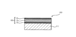
また、基材であるステンレス鋼の表面にNi及びTiからなるろう付け層を有する自己ろう付け性複合材がある(例えば、特許文献2参照)。この自己ろう付け性複合材は、図6に示すように、基材11の表面に、基材11側からNi又はNi合金層12、Ti又はTi合金層13、Ni又はNi合金層12の順に積層されたろう付け層65を一体的に設けたものである。
In addition, there is a self-brazing composite material having a brazing layer made of Ni and Ti on the surface of stainless steel as a base material (see, for example, Patent Document 2). As shown in FIG. 6, this self-brazing composite material has a Ni or
前述した特許文献2記載の自己ろう付け性複合材60のろう付け層65(ろう材)は、Ti又はTi合金が60〜70mass%、Ni又はNi合金が40〜30mass%の比率で構成されている。このため、被ろう付け材がステンレス鋼などのFe成分を含む材料である場合、ろう付け処理温度、例えば1150℃にてろう材が溶融した際に、被ろう付け材のFe成分がろう材中に溶出し、被ろう付け材が侵食されることがある。ろう付け処理後のろう付け接合部におけるFe成分の濃度は、ろう材におけるNi/Tiの比率に応じて約20〜40mass%の範囲で変化する。
The brazing layer 65 (brazing material) of the self-brazing
ここで、被ろう付け材の侵食度合いは、ろう材の量が多くなるにつれて大きくなる。このため、侵食の度合いによっては、被ろう付け材の構造強度が著しく損なわれたり、被ろう付け材の薄肉化が生じてしまう。その結果、ろう付け接合部の強度が低下するという問題があった。 Here, the degree of erosion of the brazing material increases as the amount of brazing material increases. For this reason, depending on the degree of erosion, the structural strength of the brazing material is significantly impaired, or the brazing material is thinned. As a result, there has been a problem that the strength of the brazed joint is lowered.
この被ろう付け材の侵食を防ぐべく、ろう付け層の構成材として、Ni又はNi合金層、Ti又はTi合金層と共にFe又はFe合金層を用いたろう付け用複合材がある。Fe又はFe合金層を用いることで、ろう材の溶融時、ろう材中にFe又はFe合金層のFe成分が溶解するため、被ろう付け材のFe成分がろう材中に溶出するのが抑制される。その結果、被ろう付け材の侵食が抑制される。 In order to prevent the brazing material from eroding, as a constituent material of the brazing layer, there is a brazing composite material using a Ni or Ni alloy layer, a Ti or Ti alloy layer and an Fe or Fe alloy layer. By using the Fe or Fe alloy layer, when the brazing material is melted, the Fe component of the Fe or Fe alloy layer is dissolved in the brazing material, so that the elution of the Fe component of the brazing material into the brazing material is suppressed. Is done. As a result, erosion of the brazing material is suppressed.
ところで、特許文献2記載のろう付け用複合材60や、ろう付け層の構成材にFe又はFe合金層を用いたろう付け用複合材を、被ろう付け材とろう付けする際、ろう付け処理に先立ってろう付け用複合材に焼鈍処理を施した後、プレス成形を行っている。焼鈍処理は、プレス成形時の伸びを確保するために行われるものである。
By the way, when brazing a brazing
しかしながら、この焼鈍処理の際に、ろう付け層を構成するTi又はTi合金層のTi成分とFe又はFe合金層のFe成分とが反応し、Ti又はTi合金層とFe又はFe合金層との界面に脆い金属間化合物の層が生成される。その結果、プレス成形時に、ろう付け用複合材に破断や破損が生じたり、基材からろう付け層が剥離したりするおそれがあり、延いては、ろう付け組み立て工程において不具合が生じるおそれがあった。 However, during this annealing treatment, the Ti component of the Ti or Ti alloy layer constituting the brazing layer reacts with the Fe component of the Fe or Fe alloy layer, and the Ti or Ti alloy layer and the Fe or Fe alloy layer are reacted. A brittle intermetallic layer is produced at the interface. As a result, at the time of press molding, the brazing composite material may be broken or damaged, or the brazing layer may be peeled off from the base material, which may cause problems in the brazing assembly process. It was.
以上の事情を考慮して創案された本発明の目的は、焼鈍処理時に脆い金属間化合物の層が生成されるおそれがなく、かつ、被ろう付け材が侵食されるおそれが殆どないろう付け用複合材及びそれを用いたろう付け製品を提供することにある。 The purpose of the present invention created in view of the above circumstances is that there is no possibility of forming a brittle intermetallic compound layer during annealing, and there is almost no risk of the brazing material being eroded. It is to provide a composite material and a brazing product using the same.
上記目的を達成すべく本発明に係るろう付け用複合材は、基材の表面にろう付け層を一体的に設けてなる複合材で構成され、被ろう付け部材とろう付けされるろう付け用複合材において、
上記ろう付け層が、少なくとも3層の積層体で構成され、かつ、第1の金属及び第2の金属の各層の間に、両金属が反応して脆い金属間化合物が生成されるのを抑制する反応防止層を設けたものである。反応防止層の層厚は6μm以上であることが好ましい。
To achieve the above object, the brazing composite material according to the present invention is composed of a composite material in which a brazing layer is integrally provided on the surface of a base material, and is brazed to a brazed member. In composite materials,
The brazing layer is composed of a laminate of at least three layers, and between the first metal layer and the second metal layer, both metals react to prevent formation of a brittle intermetallic compound. The reaction preventing layer is provided. The layer thickness of the reaction preventing layer is preferably 6 μm or more.
また、本発明に係るろう付け用複合材は、基材の表面にろう付け層を一体的に設けてなる複合材で構成され、被ろう付け部材とろう付けされるろう付け用複合材において、
上記ろう付け層が、Ti又はTi合金層、Ni又はNi合金層、Fe又はFe合金層の少なくとも3層の積層体で構成され、かつ、Ti又はTi合金層とFe又はFe合金層との間に、TiとFeとが反応して脆い金属間化合物が生成されるのを抑制する反応防止層としてNi又はNi合金層を配置したものである。
Further, the brazing composite material according to the present invention is composed of a composite material in which a brazing layer is integrally provided on the surface of a base material, and in the brazing composite material to be brazed with a member to be brazed,
The brazing layer is composed of a laminate of at least three layers of Ti or Ti alloy layer, Ni or Ni alloy layer, Fe or Fe alloy layer, and between the Ti or Ti alloy layer and the Fe or Fe alloy layer. In addition, a Ni or Ni alloy layer is disposed as a reaction preventing layer that suppresses the formation of brittle intermetallic compounds by reaction of Ti and Fe.
ここで、Ni又はNi合金層の層厚は6μm以上であることが好ましい。 Here, the thickness of the Ni or Ni alloy layer is preferably 6 μm or more.
ろう付け層の[Ni]重量と[Ni+Ti]重量との比は0.55〜0.70であることが好ましい。また、ろう付け層全体に占めるFeの割合は10〜30mass%であることが好ましい。 The ratio of [Ni] weight to [Ni + Ti] weight of the brazing layer is preferably 0.55 to 0.70. Moreover, it is preferable that the ratio of Fe which occupies for the whole brazing layer is 10-30 mass%.
基材はFeを主成分とする合金で構成することが好ましい。また、Feを主成分とする合金はステンレス鋼であることが好ましい。 The base material is preferably composed of an alloy containing Fe as a main component. Further, the alloy containing Fe as a main component is preferably stainless steel.
一方、本発明に係るろう付け製品は、前述したろう付け用複合材と被ろう付け部材とをろう付け接合したものである。 On the other hand, the brazing product according to the present invention is obtained by brazing and joining the above-mentioned brazing composite material and a member to be brazed.
本発明によれば、プレス成形性が良好で、被ろう付け材や基材の侵食を抑制可能なろう付け用複合材を得ることができるという優れた効果を発揮する。 According to the present invention, it is possible to obtain a brazing composite material having good press formability and capable of suppressing the erosion of a brazing material and a base material.
以下、本発明の好適一実施の形態を添付図面に基づいて説明する。 DESCRIPTION OF EXEMPLARY EMBODIMENTS Hereinafter, a preferred embodiment of the invention will be described with reference to the accompanying drawings.
本発明の好適一実施の形態に係るろう付用複合材の断面図を図1に示す。 A cross-sectional view of a brazing composite material according to a preferred embodiment of the present invention is shown in FIG.
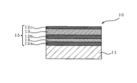
図1に示すように、本実施の形態に係るろう付用複合材10は、被ろう付け部材とろう付けされるものであって、基材11の表面(図1中では上面のみ)にろう付け層15を一体的に設けてなるものである。このろう付け用複合材10に適宜、圧延加工を施すことで、所望の厚さのろう付け用複合材(最終製品)が得られる。ここで言う基材11の表面は、外部に露出する全ての面を示している。
As shown in FIG. 1, a brazing
ろう付け層15は、Ti又はTi合金層(以下、Ti層と表す)、Ni又はNi合金層(以下、Ni層と表す)、Fe又はFe合金層(以下、Fe層と表す)の少なくとも3層の積層体で構成されるものである。より具体的に説明すると、ろう付け層15は、基材11側から順に、Fe層14、Ti層13を配置、積層する際、基材11とFe層14との間及びFe層14とTi層13との間に、それぞれ反応防止層であるNi層(反応防止層)12a,12bを介在させ、また、Ti層13上にもNi層12cを配置、積層し、クラッドしたものである。
The brazing layer 15 includes at least 3 of a Ti or Ti alloy layer (hereinafter referred to as a Ti layer), a Ni or Ni alloy layer (hereinafter referred to as a Ni layer), and a Fe or Fe alloy layer (hereinafter referred to as a Fe layer). It is composed of a laminate of layers. More specifically, the brazing layer 15 is arranged between the
基材11は、後述するろう付け製品を構成する構成部材(被ろう付け部材)と同一又はほぼ同一の材料で構成される。例えば、基材11の構成材としては、Feを主成分とするFe基合金が好ましく、より好ましくはステンレス鋼、特に好ましくはオーステナイト系ステンレス鋼が挙げられる。
The
ろう付け層15におけるNi層12a〜12cの内、Fe層14とTi層13との間に介在されるNi層12b(以下、第2Ni層12bと表す)の層厚は6μm以上に調整される。ここで、第2Ni層12bの層厚が6μm未満だと、Ni層の層厚が薄すぎて、焼鈍処理時にFeとTiとの反応を防止しきれず、Fe層14とTi層13との間に、Ti-Fe系金属間化合物の層が生成されるためである。その結果、後述するプレス成形時にろう付け用複合材10に割れ(破断)が生じる。
Of the Ni layers 12a to 12c in the brazing layer 15, the layer thickness of the Ni layer 12b (hereinafter referred to as the second Ni layer 12b) interposed between the
第2Ni層12bの層厚を6μm以上と規定した根拠は、次のようなものである。ある熱処理条件下(例えば、900〜942℃×数分間)で、Ti層/Ni層/Fe層の積層体に焼鈍処理を施した場合、Ti層とNi層との界面に層厚約4μmのNi-Ti反応層が、Ni層とFe層との界面に層厚約2μmのNi-Fe反応層がそれぞれ生成される。このため、第2Ni層12bの層厚が、各反応層の層厚の合計値以上(6μm以上)であれば、FeとTiとの直接反応を防ぐことができると考えられる。 The grounds for defining the thickness of the second Ni layer 12b as 6 μm or more are as follows. When an annealing treatment is performed on the laminate of Ti layer / Ni layer / Fe layer under a certain heat treatment condition (for example, 900 to 942 ° C. × several minutes), the layer thickness is about 4 μm at the interface between the Ti layer and the Ni layer. A Ni—Ti reaction layer having a thickness of about 2 μm is formed at the interface between the Ni layer and the Fe layer. For this reason, if the layer thickness of the 2nd Ni layer 12b is more than the total value of the layer thickness of each reaction layer (6 micrometers or more), it is thought that the direct reaction of Fe and Ti can be prevented.
ろう付け層15におけるNi層12a〜12cの形成方法については、特に限定するものではない。例えば、単にNi層12a、Fe層14、Ni層12b、Ti層13、Ni層12cの順に積層したり、両面にNiめっき膜を設けたFe層14,Ti層13を積層したりして、ろう付け層15を形成してもよい。
The method for forming the Ni layers 12a to 12c in the brazing layer 15 is not particularly limited. For example, simply layering the Ni layer 12a, the
焼鈍処理の熱処理条件を、例えば、900〜942℃(942℃は除く)としたのは、次のような理由からである。942℃は、Ni-Ti界面の溶融開始温度である。このため、焼鈍温度が942℃以上だと、Ni-Ti系合金が溶融し始めてしまい、ろう材の形状を保持することができなくなるためである。その結果、ろう材の表面状態が悪化してしまい、脆い金属間化合物の層が露出したり、後述するプレス成形時にろう付け層15が剥離したりする。また、焼鈍温度が900℃未満だと、基材11を十分に軟化させることができず、後述するプレス成形時にろう付け用複合材10に割れ(破断)が生じるためである。焼鈍処理の温度、加熱時間は、ろう付け層15の層構造、各層の組成及び層厚に応じて、適宜調整される。
The reason why the annealing heat treatment conditions are set to, for example, 900 to 942 ° C. (excluding 942 ° C.) is as follows. 942 ° C. is the melting start temperature of the Ni—Ti interface. For this reason, when the annealing temperature is 942 ° C. or higher, the Ni—Ti-based alloy starts to melt, and the shape of the brazing material cannot be maintained. As a result, the surface state of the brazing material is deteriorated, and a brittle intermetallic compound layer is exposed, or the brazing layer 15 is peeled off during press molding described later. Moreover, when the annealing temperature is less than 900 ° C., the
ろう付け層15の[Ni]重量と[Ni+Ti]重量との比(Ni/Ni+Ti)は0.55〜0.70に調整される。これらの調整は、層12,13の各層厚の調整、層12,13の各合金組成の調整などによってなされる。ここで、Ni/Ni+Tiが0.55未満、又は0.70を超えると、ろう材全体の融点が上昇するので、ろう付け処理温度が高温(例えば、1200℃以上)となってしまう。その結果、被ろう付け材や基材11自体の強度が低下するため、好ましくない。
The ratio (Ni / Ni + Ti) of the [Ni] weight and the [Ni + Ti] weight of the brazing layer 15 is adjusted to 0.55 to 0.70. These adjustments are made by adjusting the thicknesses of the
ろう付け層15全体に占めるFeの割合は10〜30mass%、好ましくは15〜25mass%に調整される。言い換えると、ろう付け用複合材10は、ろう付け層15全体の組成がNi-Ti-10〜30mass%Feとなるように調整したものである。これらの調整は、層12,13,14の各層厚の調整、層12,13,14の各合金組成の調整などによってなされる。ここで、Feの割合が10mass%未満だと、被ろう付け材や基材11からFe成分が溶出するのを十分に抑制することができない。また、Feの割合が30mass%を超えると、ろう材全体の融点が上昇するので、ろう付け処理温度がより高温となってしまい、結果的に被ろう付け材や基材11の強度が低下する。
The ratio of Fe in the entire brazing layer 15 is adjusted to 10 to 30 mass%, preferably 15 to 25 mass%. In other words, the brazing
このようにして得られたろう付け用複合材10に、適宜、焼鈍処理、プレス成形(プレス加工)を施して所望の形状の半製品に形成した後、その半製品と接合を行う被ろう付け部材(図示せず)とを組み合わせ、ろう付け接合を行う部分(ろう付け接合部)を接触させる。その後、ろう付け接合部をメインにして、これらの組み合わせ部材に加熱によるろう付け処理を施すことで、ろう付け製品が得られる。あるいは、被ろう付け部材として、ろう付け用複合材10を用いてもよい。例えば、本実施の形態に係るろう付け用複合材10を複数個用意し、各複合材10に適宜プレス加工を施してそれぞれ所望の形状の半製品に形成した後、それらの半製品を組み合わせ、ろう付け接合部を接触させる。その後、これらの組み合わせ部材に加熱によるろう付け処理を施すことで、ろう付け製品を得るようにしてもよい。
The brazing
ろう付け製品としては、EGR用クーラ等の高温・高腐食性のガス又は液体に晒される熱交換器、燃料電池の改質器用クーラ、燃料電池部材、オイルクーラ、ラジエータ、二次電池部材などが挙げられる。 Brazing products include heat exchangers exposed to high-temperature, highly corrosive gases or liquids such as EGR coolers, fuel cell reformer coolers, fuel cell members, oil coolers, radiators, secondary battery members, etc. Can be mentioned.
本実施の形態においては、基材側からNi層12a、Fe層14、Ni層12b、Ti層13、Ni層12cの順に積層してなる5層構造のろう付け層15を有するろう付け用複合材10について説明を行った。しかし、ろう付け層の構造は、これに特に限定するものではなく、Fe層14とTi層13との間に反応防止層であるNi層を介在させた層構造のろう付け層であればよい。例えば、基材側からFe層14、Ni層12b、Ti層13の順に積層してなる3層構造のろう付け層や、基材側からNi層12a、Fe層14、Ni層12b、Ti層13の順に積層してなる4層構造のろう付け層や、6層構造以上のろう付け層であってもよい。
In the present embodiment, a brazing composite having a brazing layer 15 having a five-layer structure in which a Ni layer 12a, an
また、本実施の形態においては、基材11の片面(図1中では上面)のみにろう付け層15を設けたろう付け用複合材10について説明を行ったが、これに特に限定するものではない。例えば、ろう付け層15が基材11の両面(図1中では上・下面)に設けられたろう付け用複合材であってもよい。
Moreover, in this Embodiment, although the
さらに、本実施の形態においては、箔状を呈したろう付け用複合材10を用いて説明を行ったが、複合材の形状は箔状に特に限定するものではない。例えば、棒状又はワイヤ状の基材の表面に、基材側からNi層12、Fe層14、Ni層12、Ti層13、Ni層12の順に積層してなるろう付け層15を一体的に設け、ろう付け用複合材としてもよい。この場合、各層12,13,14の形成は、メッキ法、押出法、造管法などによってなされる。
Furthermore, in this Embodiment, although demonstrated using the
次に、本実施の形態の作用を説明する。 Next, the operation of the present embodiment will be described.
本実施の形態に係るろう付け用複合材10に焼鈍処理を施すと、基材11が軟化される。また、ろう付け層15におけるTi層13のTi成分と、Ni層12b,12cのNi成分とが徐々に溶け出し、相互に拡散される。さらに、この焼鈍処理によって、ろう付け層15におけるFe層14のFe成分と、Ni層12a,12bのNi成分とが徐々に溶け出し、相互に拡散される。これによって、Ti層13とNi層12b,12cとの界面にはNi-Ti反応層が、Fe層14とNi層12a,12bとの界面にはNi-Fe反応層が生成される。
When the annealing treatment is applied to the
ここで、本実施の形態に係るろう付け用複合材10は、第2Ni層12bの層厚を、Ti成分とFe成分との直接接触を妨げるのに十分な厚さ(6μm以上)に調整している。このため、Fe層14とTi層13との界面にTi-Fe系金属間化合物の層が生成するのが抑制される。
Here, in the
この焼鈍処理後のろう付け用複合材10にプレス加工を施し、半製品を作製する。この時、ろう付け用複合材10における基材11は、焼鈍処理によって十分に軟化されている。また、ろう付け層15のFe層14とTi層13との界面に、Ti-Fe系金属間化合物の層はほとんど生成されていない。よって、プレス加工時に割れが生じることはなく、所望の形状の半製品を歩留りよく得ることができる。
The brazing
この半製品と被ろう付け部材(図示せず)とを組み合わせ、ろう付け接合部を接触させる。その後、これらの組み合わせ部材に、加熱によるろう付け処理を施すことで、ろう付け接合部においてろう付け層15(ろう材)の溶融反応が生じる。ろう付けは、例えば、1×10⁻²Pa以下の真空雰囲気下、1130〜1150℃の温度で行う。 This semi-finished product and a member to be brazed (not shown) are combined and the brazed joint is brought into contact. Thereafter, these combination members are subjected to a brazing treatment by heating, so that a brazing reaction of the brazing layer 15 (brazing material) occurs at the brazed joint. The brazing is performed at a temperature of 1130 to 1150 ° C. in a vacuum atmosphere of 1 × 10 −2 Pa or less, for example.
このろう付け処理により、先ず、ろう材におけるTi層13とNi層12b,12cとの拡散反応が更に進行し、合金化される。ここで、単体では融点が1400℃を超えるNi,Tiを、[Ni]重量と[Ni+Ti]重量との比(Ni/Ni+Ti)を0.55〜0.70に調整して合金化させることによって、ろう材の一部(図1中では上部)において融点が低下し、約1100〜1200℃の温度でろう材が溶融し始める。
By this brazing treatment, first, the diffusion reaction between the
その後、Fe層14が溶融して、Ti成分、Ni成分、及びFe成分が混合され、ろう材の流動が生じる。ろう材の流動が生じる前に、ろう材中にFe層14が溶融するため、溶融したろう材全体のFe濃度は、ろう付け層15全体のFe濃度と同じ10〜30mass%となる。ここで、ろう付け処理の際に、被ろう付け材や基材11のFe成分がろう材中に溶け込んだとしても、溶け込みが生じるのはFe濃度が飽和に達するまでであり、溶け込み可能なFe量には限界がある。よって、被ろう付け材や基材11のFe成分のろう材中への溶け込みが抑制され、被ろう付け材や基材11に侵食が発生するのを大幅に低減することができる。また、ろう材中のFe濃度は、ろう材の湯流れ性を阻害しないように10〜30mass%に調整していることから、ろう材の湯流れ性も良好となる。その結果、ろう付け後において、被ろう付け材と基材11とのろう付け接合部の強度低下が生じることはなく、ろう付け接合部の信頼性は良好である。
Thereafter, the
このように、本実施の形態に係るろう付け用複合材10と被ろう付け部材(ステンレス鋼板)とをろう付け接合することで、ろう付け接合部における侵食の少ないろう付け製品を、工業的に安定して製造することができる。このろう付け製品は、ろう付け前後において被ろう付け材や基材11の強度低下がほとんどなく、また、被ろう付け材や基材11に侵食がほとんど生じておらず、高い信頼性を有する。
Thus, by brazing and joining the
また、本実施の形態に係るろう付け用複合材10(図1参照)のように、ろう材と基材11とを一体的に設けたものを用いることで、基材11と被ろう付け部材とのろう付け接合部にろう材を配置する作業が不要となる。このため、良好なろう付け生産性で、ろう付け製品を得ることができる。
Moreover, the
以上、本発明は、上述した実施の形態に限定されるものではなく、他にも種々のものが想定されることは言うまでもない。 As described above, the present invention is not limited to the above-described embodiment, and it goes without saying that various other things are assumed.
次に、本発明について、実施例に基づいて説明するが、本発明はこれらの実施例に限定されるものではない。 Next, although this invention is demonstrated based on an Example, this invention is not limited to these Examples.
(実施例1)
板厚が0.6mmのNi板、板厚が2.3mmのTi板、板厚が0.8mmのNi板、板厚が0.5mmのFe板、板厚が0.8mmのNi板を順に重ね合わせて5層構造の積層体を形成した。この積層体に熱間圧延処理を施して、板厚が1.4mmのクラッド板を得た。このクラッド板に冷間圧延処理を施して、板厚が0.25mmのクラッド板を作製した。
(Example 1)
A Ni plate having a plate thickness of 0.6 mm, a Ti plate having a plate thickness of 2.3 mm, a Ni plate having a plate thickness of 0.8 mm, a Fe plate having a plate thickness of 0.5 mm, and a Ni plate having a plate thickness of 0.8 mm are sequentially stacked. A layered laminate was formed. This laminate was hot-rolled to obtain a clad plate having a thickness of 1.4 mm. This clad plate was cold-rolled to produce a clad plate having a thickness of 0.25 mm.
このクラッド板と、基材である厚さ2.25mmのステンレス鋼板(SUS304板材)とを重ね合わせ、圧延法によりクラッドして複合材を作製した。この複合材に冷間圧延処理を繰り返し施し、層厚が50μmで、5層構造(Ni/Ti/Ni/Fe/Ni/(SUS))のろう付け層を有するろう付け用複合材(板厚が0.5mm)を作製した。第2Ni層(Fe層とTi層との間のNi層)の層厚は8μm、ろう付け層全体に占めるFe濃度は11mass%である。 This clad plate was superposed on a 2.25 mm thick stainless steel plate (SUS304 plate material) as a base material and clad by a rolling method to produce a composite material. This composite material is repeatedly subjected to cold rolling treatment, and the thickness of the layer is 50 μm. The composite material for brazing (sheet thickness) has a five-layer structure (Ni / Ti / Ni / Fe / Ni / (SUS)). Was 0.5 mm). The thickness of the second Ni layer (the Ni layer between the Fe layer and the Ti layer) is 8 μm, and the Fe concentration in the entire brazing layer is 11 mass%.
(実施例2)
板厚が0.4mmのNi板、板厚が0.9mmのFe板、板厚が0.7mmのNi板、板厚が2.3mmのTi板、板厚が0.7mmのNi板を順に重ね合わせて5層構造の積層体を形成した。その後は実施例1と同様にして、層厚が50μmで、5層構造(Ni/Fe/Ni/Ti/Ni/(SUS))のろう付け層を有するろう付け用複合材(板厚が0.5mm)を作製した。第2Ni層の層厚は7μm、ろう付け層全体に占めるFe濃度は20mass%である。
(Example 2)
A Ni plate having a thickness of 0.4 mm, an Fe plate having a thickness of 0.9 mm, a Ni plate having a thickness of 0.7 mm, a Ti plate having a thickness of 2.3 mm, and a Ni plate having a thickness of 0.7 mm are sequentially stacked. A layered laminate was formed. Thereafter, in the same manner as in Example 1, a brazing composite material (plate thickness is 0.5 mm) having a layer thickness of 50 μm and a brazing layer having a five-layer structure (Ni / Fe / Ni / Ti / Ni / (SUS)). mm). The thickness of the second Ni layer is 7 μm, and the Fe concentration in the entire brazing layer is 20 mass%.
(実施例3)
板厚が0.8mmのNi板、板厚が3.4mmのTi板、板厚が0.9mmのNi板、板厚が1.5mmのFe板、板厚が0.9mmのNi板を順に重ね合わせて5層構造の積層体を形成した。その後は実施例1と同様にして、層厚が75μmで、5層構造(Ni/Ti/Ni/Fe/Ni/(SUS))のろう付け層を有するろう付け用複合材(板厚が0.5mm)を作製した。第2Ni層の層厚は9μm、ろう付け層全体に占めるFe濃度は24mass%である。
(Example 3)
The thickness of the Ni plate is 0.8 mm, the Ti plate is 3.4 mm, the Ni plate is 0.9 mm, the Fe plate is 1.5 mm, and the Ni plate is 0.9 mm. A layered laminate was formed. Thereafter, in the same manner as in Example 1, a brazing composite material having a layer thickness of 75 μm and a brazing layer having a five-layer structure (Ni / Ti / Ni / Fe / Ni / (SUS)) (plate thickness of 0.5 mm). The thickness of the second Ni layer is 9 μm, and the Fe concentration in the entire brazing layer is 24 mass%.
(比較例1)
板厚が0.6mmのNi板、板厚が1.9mmのTi板、板厚が0.4mmのNi板、板厚が1.3mmのFe板、板厚が0.8mmのNi板を順に重ね合わせて5層構造の積層体を形成した。その後は実施例1と同様にして、層厚が50μmで、5層構造(Ni/Ti/Ni/Fe/Ni/(SUS))のろう付け層を有するろう付け用複合材(板厚が0.5mm)を作製した。第2Ni層の層厚は4μm、ろう付け層全体に占めるFe濃度は30mass%である。
(Comparative Example 1)
A Ni plate having a thickness of 0.6 mm, a Ti plate having a thickness of 1.9 mm, a Ni plate having a thickness of 0.4 mm, a Fe plate having a thickness of 1.3 mm, and a Ni plate having a thickness of 0.8 mm are sequentially stacked. A layered laminate was formed. Thereafter, in the same manner as in Example 1, a brazing composite material having a thickness of 50 μm and a brazing layer having a five-layer structure (Ni / Ti / Ni / Fe / Ni / (SUS)) (plate thickness of 0.5 mm). The thickness of the second Ni layer is 4 μm, and the Fe concentration in the entire brazing layer is 30 mass%.
(比較例2)
板厚が0.7mmのNi板、板厚が0.9mmのFe板、板厚が0.4mmのNi板、板厚が2.3mmのTi板、板厚が0.7mmのNi板を順に重ね合わせて5層構造の積層体を形成した。その後は実施例1と同様にして、層厚が50μmで、5層構造(Ni/Fe/Ni/Ti/Ni/(SUS))のろう付け層を有するろう付け用複合材(板厚が0.5mm)を作製した。第2Ni層の層厚は4μm、ろう付け層全体に占めるFe濃度は20mass%である。
(Comparative Example 2)
5 mm by sequentially stacking a Ni plate having a thickness of 0.7 mm, a Fe plate having a thickness of 0.9 mm, a Ni plate having a thickness of 0.4 mm, a Ti plate having a thickness of 2.3 mm, and a Ni plate having a thickness of 0.7 mm. A layered laminate was formed. Thereafter, in the same manner as in Example 1, a brazing composite material having a layer thickness of 50 μm and a brazing layer having a five-layer structure (Ni / Fe / Ni / Ti / Ni / (SUS)) (plate thickness of 0.5 mm). The thickness of the second Ni layer is 4 μm, and the Fe concentration in the entire brazing layer is 20 mass%.
(比較例3)
板厚が1.2mmのNi板、板厚が1.1mmのFe板、板厚が1.2mmのNi板、板厚が3.7mmのTi板、板厚が0.3mmのNi板を順に重ね合わせて5層構造の積層体を形成した。その後は実施例1と同様にして、層厚が75μmで、5層構造(Ni/Fe/Ni/Ti/Ni/(SUS))のろう付け層を有するろう付け用複合材(板厚が0.5mm)を作製した。第2Ni層の層厚は12μm、第3Ni層(Ti層とステンレス鋼層との間のNi層)の層厚は3μm、ろう付け層全体に占めるFe濃度は20mass%である。
(Comparative Example 3)
A Ni plate having a thickness of 1.2 mm, a Fe plate having a thickness of 1.1 mm, a Ni plate having a thickness of 1.2 mm, a Ti plate having a thickness of 3.7 mm, and a Ni plate having a thickness of 0.3 mm are sequentially stacked. A layered laminate was formed. Thereafter, in the same manner as in Example 1, a brazing composite material having a layer thickness of 75 μm and a brazing layer having a five-layer structure (Ni / Fe / Ni / Ti / Ni / (SUS)) (plate thickness of 0.5 mm). The thickness of the second Ni layer is 12 μm, the thickness of the third Ni layer (Ni layer between the Ti layer and the stainless steel layer) is 3 μm, and the Fe concentration in the entire brazing layer is 20 mass%.
(従来例1)
板厚が2.4mmのNi板、板厚が2.6mmのTi板を重ね合わせて2層構造の積層体を形成した。その後は実施例1と同様にして、層厚が50μmで、2層構造(Ni/Ti/(SUS))のろう付け層を有するろう付け用複合材(板厚が0.5mm)を作製した。
(Conventional example 1)
A Ni plate having a thickness of 2.4 mm and a Ti plate having a thickness of 2.6 mm were overlapped to form a laminate having a two-layer structure. Thereafter, in the same manner as in Example 1, a composite material for brazing (plate thickness: 0.5 mm) having a layer thickness of 50 μm and having a two-layer structure (Ni / Ti / (SUS)) brazing layer was produced.
実施例1〜3、比較例1〜3、及び従来例1の各ろう付け用複合材について、それらの積層構造、ろう付け層全体の層厚(μm)、第2Ni層の層厚(μm)、ろう付け層全体に占めるFe濃度(mass%)を表1に示す。また、各ろう付け用複合材の、ろう付け処理後の基材の残存率(%)、プレス成形性の結果も併せて表1に示す。 For each of the composite materials for brazing of Examples 1 to 3, Comparative Examples 1 to 3, and Conventional Example 1, their laminated structure, the thickness of the entire brazing layer (μm), the thickness of the second Ni layer (μm) Table 1 shows the Fe concentration (mass%) in the entire brazing layer. Table 1 also shows the results of the remaining ratio (%) of the base material after the brazing treatment and the press formability of each composite material for brazing.
ここで、各ろう付け用複合材は、ろう付け処理の前に、焼鈍処理が施される。実施例1〜3及び従来例1の各ろう付け用複合材については、連続焼鈍炉にて930×4minの焼鈍処理を行った。比較例1〜3のろう付け用複合材については、実施例1〜3及び従来例1の各ろう付け用複合材と同条件の焼鈍処理を施すと、FeとTiの反応が過剰に進行してしまい、表面に脆い層が露出したり、表面が波打つ等というように表面形状が悪化する。よって、比較例1〜3のろう付け用複合材については、表面形状が悪化しない条件、具体的には連続焼鈍炉にて900×4minの処理条件で焼鈍処理を行った。 Here, each brazing composite material is subjected to an annealing treatment before the brazing treatment. About each composite material for brazing of Examples 1-3 and the prior art example 1, the annealing process of 930 * 4min was performed in the continuous annealing furnace. About the composite material for brazing of Comparative Examples 1-3, when the annealing process of the same conditions as each brazing composite material of Examples 1-3 and the prior art example 1 is performed, reaction of Fe and Ti will advance excessively. Therefore, the surface shape is deteriorated such that a fragile layer is exposed on the surface or the surface is wavy. Therefore, the brazing composite materials of Comparative Examples 1 to 3 were subjected to annealing treatment under conditions where the surface shape did not deteriorate, specifically, under a treatment condition of 900 × 4 min in a continuous annealing furnace.
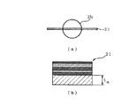
焼鈍処理後の各ろう付け用複合材は、プレス成形が施される。具体的には、焼鈍処理後の各ろう付け用複合材から、図2(a),図2(b)に示す試料(20mm×25mm)21を切り出した。その後、各試料21の長辺の垂直二等分線を折り目にして各試料21に90°曲げ加工を施し、試料31を作製した。この時、ろう付け層が曲げ内側に位置するように折り曲げた。
Each brazing composite material after the annealing treatment is subjected to press molding. Specifically, a sample (20 mm × 25 mm) 21 shown in FIGS. 2A and 2B was cut out from each brazing composite material after the annealing treatment. Thereafter, the vertical bisector of the long side of each
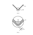
その後、各試料31の谷部を鉛直下向きに位置させた状態で熱処理炉内に配置し、各試料31にろう付け処理を施した。ろう付け処理は、1×10⁻²Pa以下の真空雰囲気下、
常温から900℃まで10℃/minで昇温(ステップA)、
900℃×30minの等温保持(ステップB)、
900℃から1150℃まで10℃/minで昇温(ステップC)、
1150℃×15minの等温保持(ステップD)、
急冷(ステップE)、
という熱サイクルパターンで行った。
After that, each
Temperature rise from room temperature to 900 ° C at 10 ° C / min (Step A),
900 ℃ x 30min isothermal hold (Step B),
Increase the temperature from 900 ℃ to 1150 ℃ at 10 ℃ / min (Step C),
1150 ℃ × 15min isothermal hold (Step D),
Rapid cooling (step E),
The heat cycle pattern was used.
その後、図4(a)に示すように、熱処理後の各試料41を短辺の垂直二等分線で切断した。各試料41の断面を観察し、基材の侵食度合いを評価した。侵食度合いは、基材の残存率(%)を用いて行った。基材の残存率(%)は、熱処理前における試料21の基材厚さをta、溶融凝固したろう材42により基材が最も薄くなった部分の基材厚さをtbとすると、(tb/ta)×100で表される。
Thereafter, as shown in FIG. 4A, each
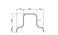
また、焼鈍処理後の各ろう付け用複合材から、100mm×100mmの試料を切り出した。その後、図5に示す断面形状を呈した凸部51を形成すべく、各試料にプレス成形を施し、プレス成形性の評価を行った。凸部51における各曲げ部の曲げ半径(R半径)は1mmとした。
Further, a 100 mm × 100 mm sample was cut out from each brazing composite material after the annealing treatment. Then, in order to form the

表1に示すように、実施例1〜3の各ろう付け用複合材は、ろう付け層全体に占めるFe濃度が11mass%、20mass%、24mass%であり、規定範囲(10〜30mass%)に調整されていた。このため、ろう付け処理時、基材(又は被ろう付け材)のFe成分がろう材中に溶出するのが大幅に抑制され、その結果、実施例1〜3の各ろう付け用複合材は、基材残存率が83%、85%、87%といずれも80%以上であった。また、ろう材の湯流れ性も良好であった。 As shown in Table 1, in each of the brazing composite materials of Examples 1 to 3, the Fe concentration in the entire brazing layer is 11 mass%, 20 mass%, and 24 mass%, and within a specified range (10 to 30 mass%). It was adjusted. For this reason, at the time of brazing treatment, it is greatly suppressed that the Fe component of the base material (or brazing material) is eluted into the brazing material. As a result, each of the brazing composite materials of Examples 1 to 3 is The residual ratio of the base material was 83%, 85%, 87%, and all were 80% or more. Also, the hot metal flowability of the brazing material was good.
また、実施例1〜3の各ろう付け用複合材は、第2Ni層の層厚が8μm、7μm、9μmであり、規定範囲(6μm以上)に調整されていた。このため、Fe層とTi層との界面にFe-Ti系の脆い金属間化合物が生成されず、その結果、実施例1〜3の各ろう付け用複合材は、図5に示した凸部51を形成するプレス成形を施しても割れが観察されず、プレス成形性が良好であった。 In each of the brazing composite materials of Examples 1 to 3, the thickness of the second Ni layer was 8 μm, 7 μm, and 9 μm, and was adjusted to a specified range (6 μm or more). For this reason, an Fe—Ti-based brittle intermetallic compound is not generated at the interface between the Fe layer and the Ti layer, and as a result, each of the brazing composite materials of Examples 1 to 3 has the convex portion shown in FIG. Even when press forming to form 51 was performed, no cracks were observed and the press formability was good.
これに対して、比較例1,2の各ろう付け用複合材は、Fe層とTi層の位置が逆になってはいるが、ろう付け層全体に占めるFe濃度が30mass%、20mass%であり、規定範囲(10〜30mass%)に調整されていた。また、比較例3のろう付け用複合材は、ろう付け層全体に占めるFe濃度が20mass%であり、規定範囲(10〜30mass%)に調整されていた。このため、比較例1〜3の各ろう付け用複合材は、基材残存率が90%、88%、85%といずれも80%以上であった。また、ろう材の湯流れ性も良好であった。 On the other hand, in the brazing composite materials of Comparative Examples 1 and 2, the positions of the Fe layer and the Ti layer are reversed, but the Fe concentration in the entire brazing layer is 30 mass% and 20 mass%. Yes, it was adjusted to the specified range (10-30 mass%). In the brazing composite material of Comparative Example 3, the Fe concentration in the entire brazing layer was 20 mass%, which was adjusted to the specified range (10 to 30 mass%). For this reason, the brazing composite materials of Comparative Examples 1 to 3 each had a base material residual ratio of 90%, 88%, and 85%, which were 80% or more. Also, the hot metal flowability of the brazing material was good.
しかしながら、比較例1,2の各ろう付け用複合材は、第2Ni層の層厚がいずれも4μmであり、規定範囲(6μm以上)未満であった。このため、実施例1〜3と同様の焼鈍処理を行うと、Fe層とTi層との界面にFe-Ti系の脆い金属間化合物が生成してしまう。よって、これを防ぐべく、実施例1〜3よりも低温の焼鈍処理(900℃×4min)を施した。また、比較例3のろう付け用複合材は、第2Ni層の層厚が12μmであり、規定範囲(6μm以上)に調整されていた。このため、Fe層とTi層との界面にFe-Ti系の脆い金属間化合物は生成されない。しかしながら、もう1つの反応防止層である第3Ni層の層厚が3μmと非常に薄い。このため、実施例1〜3と同様の焼鈍処理を行うと、Ti層とステンレス鋼層との界面にFe-Ti系の脆い金属間化合物が生成してしまう。よって、これを防ぐべく、実施例1〜3よりも低温の焼鈍処理(900℃×4min)を施した。 However, in each of the brazing composite materials of Comparative Examples 1 and 2, the thickness of the second Ni layer was 4 μm, which was less than the specified range (6 μm or more). For this reason, when the same annealing treatment as in Examples 1 to 3 is performed, a Fe-Ti-based brittle intermetallic compound is generated at the interface between the Fe layer and the Ti layer. Therefore, in order to prevent this, annealing treatment (900 ° C. × 4 min) at a temperature lower than that of Examples 1 to 3 was performed. In the brazing composite material of Comparative Example 3, the layer thickness of the second Ni layer was 12 μm, and was adjusted to a specified range (6 μm or more). For this reason, an Fe—Ti-based brittle intermetallic compound is not generated at the interface between the Fe layer and the Ti layer. However, the thickness of the third Ni layer, which is another reaction preventing layer, is as very thin as 3 μm. For this reason, when the annealing process similar to Examples 1-3 is performed, the Fe-Ti type brittle intermetallic compound will produce | generate at the interface of Ti layer and a stainless steel layer. Therefore, in order to prevent this, annealing treatment (900 ° C. × 4 min) at a temperature lower than that of Examples 1 to 3 was performed.
その結果、比較例1〜3の各ろう付け用複合材においては、基材が十分に軟化されず、各ろう付け用複合材全体の伸びが低下した。よって、比較例1〜3の各ろう付け用複合材は、図5に示した凸部51を形成するプレス成形を施すと割れが発生し、プレス成形性が悪かった。
As a result, in each brazing composite material of Comparative Examples 1 to 3, the base material was not sufficiently softened, and the elongation of each brazing composite material was lowered. Accordingly, each of the brazing composite materials of Comparative Examples 1 to 3 was cracked when subjected to press forming to form the
一方、従来例1のろう付け用複合材は、プレス成形性及びろう材の湯流れ性は良好であるものの、ろう材がNi-Ti系の2成分系合金であるため、ろう付け処理時に基材のFe成分が多量にろう材中に溶出してしまい、基材残存率が49%と低かった。 On the other hand, the brazing composite material of Conventional Example 1 has good press formability and hot metal flowability of the brazing material, but the brazing material is a Ni-Ti-based binary alloy. A large amount of the Fe component of the material was eluted into the brazing material, and the residual ratio of the base material was as low as 49%.
以上、本発明の好適一実施の形態に係るろう付け用複合材である実施例1〜3の各ろう付け用複合材は、いずれも基材の残存率が高く、プレス成形性が良好で、ろう材の湯流れ性が良好であり、ろう付け接合部の信頼性に優れたろう付け用複合材であることがわかる。 As described above, each of the brazing composite materials of Examples 1 to 3 which is a brazing composite material according to a preferred embodiment of the present invention has a high residual rate of the base material, and has good press formability. It can be seen that the brazing material has good hot-water flow and is a brazing composite material with excellent brazing joint reliability.
本発明の好適一実施の形態に係る複合材は、EGR用クーラなどの高温で、腐食性の高いガス又は液体に晒される熱交換器のみに、その用途を限定するものではなく、その他にも、例えば、燃料電池の改質器用クーラや、燃料電池部材などの各種用途にも適用可能である。特に、棒状又はワイヤ状の複合材は、径サイズが小さく、取り扱い性が良好であることから、EGR用クーラや、燃料電池の改質器用クーラ等の熱交換器、燃料電池部材などの他にも、オイルクーラ、ラジエータ、二次電池部材などにも適用可能である。 The composite material according to a preferred embodiment of the present invention is not limited to a heat exchanger that is exposed to a highly corrosive gas or liquid at a high temperature such as an EGR cooler. For example, the present invention can be applied to various uses such as a fuel cell reformer cooler and a fuel cell member. In particular, a rod-like or wire-like composite material has a small diameter size and good handleability. Therefore, in addition to heat exchangers such as EGR coolers and fuel cell reformer coolers, fuel cell members, etc. In addition, it can also be applied to oil coolers, radiators, secondary battery members, and the like.
10 ろう付け用複合材
11 基材
12a〜12c Ni又はNi合金層
13 Ti又はTi合金層
14 Fe又はFe合金層
15 ろう付け層
DESCRIPTION OF
Claims (9)
上記ろう付け層が、少なくとも3層の積層体で構成され、かつ、第1の金属及び第2の金属の各層の間に、両金属が反応して脆い金属間化合物が生成されるのを抑制する反応防止層を設けたことを特徴とするろう付け用複合材。 In a composite material for brazing composed of a composite material in which a brazing layer is integrally provided on the surface of a base material and brazed to a member to be brazed,
The brazing layer is composed of a laminate of at least three layers, and between the first metal layer and the second metal layer, both metals react to generate a brittle intermetallic compound. A brazing composite material comprising a reaction preventing layer.
上記ろう付け層が、Ti又はTi合金層、Ni又はNi合金層、Fe又はFe合金層の少なくとも3層の積層体で構成され、かつ、Ti又はTi合金層とFe又はFe合金層との間に、TiとFeとが反応して脆い金属間化合物が生成されるのを抑制する反応防止層としてNi又はNi合金層を配置したことを特徴とするろう付け用複合材。 In a composite material for brazing composed of a composite material in which a brazing layer is integrally provided on the surface of a base material and brazed to a member to be brazed,
The brazing layer is composed of a laminate of at least three layers of Ti or Ti alloy layer, Ni or Ni alloy layer, Fe or Fe alloy layer, and between the Ti or Ti alloy layer and the Fe or Fe alloy layer. And a brazing composite material in which a Ni or Ni alloy layer is disposed as a reaction preventing layer that suppresses the formation of brittle intermetallic compounds by reaction of Ti and Fe.
A brazed product comprising the brazing composite material according to any one of claims 1 to 8 and a member to be brazed.
Priority Applications (1)
| Application Number | Priority Date | Filing Date | Title |
|---|---|---|---|
| JP2004120392A JP2005297047A (en) | 2004-04-15 | 2004-04-15 | Brazing composite material and brazing product using the same |
Applications Claiming Priority (1)
| Application Number | Priority Date | Filing Date | Title |
|---|---|---|---|
| JP2004120392A JP2005297047A (en) | 2004-04-15 | 2004-04-15 | Brazing composite material and brazing product using the same |
Publications (1)
| Publication Number | Publication Date |
|---|---|
| JP2005297047A true JP2005297047A (en) | 2005-10-27 |
Family
ID=35329224
Family Applications (1)
| Application Number | Title | Priority Date | Filing Date |
|---|---|---|---|
| JP2004120392A Pending JP2005297047A (en) | 2004-04-15 | 2004-04-15 | Brazing composite material and brazing product using the same |
Country Status (1)
| Country | Link |
|---|---|
| JP (1) | JP2005297047A (en) |
Cited By (4)
| Publication number | Priority date | Publication date | Assignee | Title |
|---|---|---|---|---|
| WO2007134515A1 (en) * | 2006-05-19 | 2007-11-29 | Beijing University Of Technology | A composite base belt of ni-based alloy for superconductor coating and a method for preparing the same |
| JP2008238189A (en) * | 2007-03-26 | 2008-10-09 | Hitachi Cable Ltd | Brazing composite material and brazing product using the same |
| CN102489816A (en) * | 2011-12-23 | 2012-06-13 | 山东大学 | Amorphous brazing process for super-nickel laminated composite material and Cr18-Ni8 stainless steel |
| CN108356443A (en) * | 2018-02-07 | 2018-08-03 | 郑州大学 | Titanium-based amorphous solder and its preparation method and application |
-
2004
- 2004-04-15 JP JP2004120392A patent/JP2005297047A/en active Pending
Cited By (4)
| Publication number | Priority date | Publication date | Assignee | Title |
|---|---|---|---|---|
| WO2007134515A1 (en) * | 2006-05-19 | 2007-11-29 | Beijing University Of Technology | A composite base belt of ni-based alloy for superconductor coating and a method for preparing the same |
| JP2008238189A (en) * | 2007-03-26 | 2008-10-09 | Hitachi Cable Ltd | Brazing composite material and brazing product using the same |
| CN102489816A (en) * | 2011-12-23 | 2012-06-13 | 山东大学 | Amorphous brazing process for super-nickel laminated composite material and Cr18-Ni8 stainless steel |
| CN108356443A (en) * | 2018-02-07 | 2018-08-03 | 郑州大学 | Titanium-based amorphous solder and its preparation method and application |
Similar Documents
| Publication | Publication Date | Title |
|---|---|---|
| TWI334238B (en) | ||
| CN100450699C (en) | Brazing clad material, and brazing method and brazing product using the same | |
| JP2005297047A (en) | Brazing composite material and brazing product using the same | |
| JP2009190080A (en) | Copper-silver brazing material and clad material for lids of electronic component packages | |
| JP5061969B2 (en) | Brazing composites and brazing products | |
| JP4239853B2 (en) | Brazing composite material, method for producing the same, and brazed product | |
| JP2021031755A (en) | Aluminum alloy material, fluxless brazed structure, and fluxless brazing method | |
| JP4196776B2 (en) | Brazing composite material and method for producing the same | |
| JPH11343531A (en) | Aluminum alloy brazing sheet for heat exchanger excellent in strength and corrosion resistance and brazing method using the brazing sheet | |
| JP4880219B2 (en) | Brazing composite material and brazed structure brazed and bonded using the same | |
| JP4239764B2 (en) | Brazing composite material and brazing method using the same | |
| JP2003117679A (en) | Composite brazing material, composite material for brazing and brazing method | |
| JP2003117686A (en) | Brazing composite material and brazing product using the same | |
| JP4507942B2 (en) | Brazing clad material and brazing product using the same | |
| JP4939158B2 (en) | Brazing material, brazing composite material and brazing structure brazed and bonded using the same | |
| JP4840190B2 (en) | Brazing composite material and brazing product using the same | |
| JP2006334605A (en) | Brazing material and brazing product using the same | |
| JP5187262B2 (en) | Brazing composite material and method for producing the same | |
| JP2004188482A (en) | Brazing method and brazing product for composite brazing material having multiple types of metal layers | |
| JP4107206B2 (en) | Brazing method using a brazing composite material | |
| JP3891137B2 (en) | Brazing composite material and brazing product using the same | |
| JP2005329440A (en) | Brazing composite material and brazing product using the same | |
| JP2006000862A (en) | Brazing composite material, brazing method using the same, and brazed product produced using the method | |
| JP2009061463A (en) | Brazing composite material and brazing product using the same | |
| JP2004291074A (en) | Brazing composite material and brazing product using the same |
Legal Events
| Date | Code | Title | Description |
|---|---|---|---|
| A621 | Written request for application examination |
Free format text: JAPANESE INTERMEDIATE CODE: A621 Effective date: 20060519 |
|
| A977 | Report on retrieval |
Free format text: JAPANESE INTERMEDIATE CODE: A971007 Effective date: 20070515 |
|
| A131 | Notification of reasons for refusal |
Free format text: JAPANESE INTERMEDIATE CODE: A131 Effective date: 20070529 |
|
| A521 | Written amendment |
Effective date: 20070727 Free format text: JAPANESE INTERMEDIATE CODE: A523 |
|
| A02 | Decision of refusal |
Effective date: 20080909 Free format text: JAPANESE INTERMEDIATE CODE: A02 |