JP2005297031A - Cylinder block casting core - Google Patents
Cylinder block casting core Download PDFInfo
- Publication number
- JP2005297031A JP2005297031A JP2004118928A JP2004118928A JP2005297031A JP 2005297031 A JP2005297031 A JP 2005297031A JP 2004118928 A JP2004118928 A JP 2004118928A JP 2004118928 A JP2004118928 A JP 2004118928A JP 2005297031 A JP2005297031 A JP 2005297031A
- Authority
- JP
- Japan
- Prior art keywords
- core
- casting
- cylinder block
- shape
- pressure
- Prior art date
- Legal status (The legal status is an assumption and is not a legal conclusion. Google has not performed a legal analysis and makes no representation as to the accuracy of the status listed.)
- Pending
Links
Images


Landscapes
- Cylinder Crankcases Of Internal Combustion Engines (AREA)
- Molds, Cores, And Manufacturing Methods Thereof (AREA)
Abstract
【課題】 本発明は、クローズドシリンダブロックのウォータジャケットの形状を精度良く形成することができるシリンダブロック鋳造用中子を提供することを課題とする。
【解決手段】 リンダブロックのウォータジャケット部を形成するために、準備する鋳造用中子12において、この中子12は、設計上のウォータジャケット部の形状に対して、鋳造圧力の影響で変形する変形量δを見込んだ歪な形状に造型した。すなわち中子12は、鋳造時に溶湯の圧力を中子12の内側及び外側に受けるが、鋳造金型の配設方向及び溶湯注入口の影響により、全体として中子12の内側の面14に溶湯圧力がかかる。この溶湯圧力Fは、中子12のセット角度θ1を打ち消す。
【選択図】 図1PROBLEM TO BE SOLVED: To provide a core for casting a cylinder block capable of accurately forming the shape of a water jacket of a closed cylinder block.
In a casting core 12 to be prepared for forming a water jacket portion of a Linda block, the core 12 is deformed by the influence of casting pressure with respect to the shape of the designed water jacket portion. It was molded into a distorted shape with the deformation amount δ expected. That is, the core 12 receives the pressure of the molten metal on the inner side and the outer side of the core 12 during casting. However, the molten metal is applied to the inner surface 14 of the core 12 as a whole due to the arrangement direction of the casting mold and the influence of the molten metal injection port. Pressure is applied. The molten metal pressure F cancels the set angle θ1 of the core 12.
[Selection] Figure 1
Description
本発明は、シリンダブロックを鋳造するダイカスト鋳造用金型の内部に配設し、前記シリンダブロックにウォータジャケット部を形成するシリンダブロック製造用中子に関する。 The present invention relates to a cylinder block manufacturing core that is disposed inside a die casting mold for casting a cylinder block and forms a water jacket portion on the cylinder block.
従来シリンダブロックにウォータジャケットを形成するため使用するシリンダブロック鋳造用中子として、中子の側面にサイド巾木を有する中子(砂中子ともいう。)が知られている(例えば、特許文献1参照。)。
特許文献1を次図に基づいて説明する。
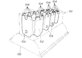
図12は従来の技術の基本構成を説明した図であり、シリンダブロック鋳造用砂中子101は、ウォータジャケット形成部102の側面に設けるサイド巾木103・・・(・・・は複数を示す。以下同じ。)と、ウォータジャケット形成部102に設け鋳造金型に突き当てる端面巾木104・・・とを有する砂中子である。
Patent document 1 is demonstrated based on the following figure.
FIG. 12 is a diagram for explaining the basic structure of the prior art. The
このサイド巾木103・・・を鋳造金型の一部により支持しつつ鋳造金型を閉じ、金型のキャビティ内に溶湯を充填し、キャビティ内の溶湯を固化させた後、金型内から砂中子と一体の鋳物を取出し、鋳物内の砂中子を崩壊させ、除去して、目的物としてのシリンダブロック105を得るというものである。
The side
従来、一般に高圧鋳造に砂中子を使用することは、砂中子の破損(又は折損)や変形が発生するため不向きであるとされており、砂中子を使用して鋳造する際は、低圧鋳造又は中圧鋳造が主に用いられてきた。 Conventionally, it is generally said that using a sand core for high pressure casting is unsuitable due to breakage (or breakage) or deformation of the sand core, and when casting using a sand core, Low pressure casting or medium pressure casting has been mainly used.
砂中子の折損に対しては、中子造型の際、高圧力により砂中子を固めて砂中子の強度を上げることで砂中子の耐折損性は向上し、折損の起きにくい砂中子を得ることができる。
しかし、高圧の溶湯は砂中子を変形させ、金型内で砂中子の変形を引き起こす場合があるため、ウォータジャケットの形状を精度良く形成することは困難であった。
For core breakage, the core core is hardened by high pressure to increase the strength of the sand core during core molding. You can get a core.
However, since the high-pressure molten metal may deform the sand core and cause deformation of the sand core in the mold, it is difficult to accurately form the shape of the water jacket.
そこで本発明は、シリンダブロックのウォータジャケットの形状を精度良く形成できるシリンダブロック鋳造用中子を提供することを課題とする。 Then, this invention makes it a subject to provide the core for cylinder block casting which can form the shape of the water jacket of a cylinder block accurately.
請求項1に係る発明は、シリンダブロックのウォータジャケット部を形成するために、準備する鋳造用中子において、この中子は、設計上のウォータジャケット部の形状に対して、鋳造圧力の影響で変形する変形量を見込んだ歪な形状にしたことを特徴とする。 In the invention according to claim 1, in the casting core to be prepared for forming the water jacket portion of the cylinder block, the core is affected by the casting pressure with respect to the shape of the designed water jacket portion. It is characterized by a distorted shape that anticipates the amount of deformation to be deformed.
請求項2に係る発明は、中子は、中子造型に必要な抜き勾配を備え、且つこの勾配を増減することで歪な形状にしたことを特徴とする。 The invention according to claim 2 is characterized in that the core has a draft angle necessary for core molding, and is formed into a distorted shape by increasing or decreasing the gradient.
請求項1に係る発明では、あらかじめ、中子の形状を設計上のウォータジャケット部の形状に対して、鋳造圧力の影響で変形する変形量を見込んだ歪な形状にしたので、シリンダブロック内にウォータジャケットを精度良く形成することができるという利点がある。 In the invention according to claim 1, the shape of the core is previously distorted to allow for deformation due to the influence of casting pressure with respect to the shape of the designed water jacket portion. There is an advantage that the water jacket can be formed with high accuracy.
請求項2に係る発明では、中子の歪な形状は、既存の抜き勾配に変量分を増減するだけで行える。
既存の抜き勾配を変化させるだけであり、中子に簡便に反映することがでる。
この結果、中子造型コストの高騰化を抑えることができるという利点がある。
In the invention according to claim 2, the distorted shape of the core can be achieved by simply increasing or decreasing the variable amount to the existing draft.
It only changes the existing draft and can be easily reflected in the core.
As a result, there is an advantage that an increase in core molding cost can be suppressed.
本発明を実施するための最良の形態を添付図に基づいて以下に説明する。なお、図面は符号の向きに見るものとする。
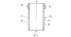
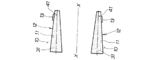
図1は本発明の原理を説明する図(鋳造前における中子の形状)であり、シリンダブロック10のウォータジャケット部11を形成するために、準備する鋳造用中子12において、鋳造圧力の影響により変形する変形量をあらかじめ見込んだ見込み量δをもたせて造型したシリンダブロック鋳造用中子12の断面形状を示す。原理を分かり易く説明するため、実際の形状よりも中子の見込み量δは大目に設定した。なお、軸X−Xはシリンダブロックの軸である。
The best mode for carrying out the present invention will be described below with reference to the accompanying drawings. The drawings are viewed in the direction of the reference numerals.
FIG. 1 is a diagram for explaining the principle of the present invention (core shape before casting). In order to form the
鋳造金型のキャビティ内部において、中子12の一部を構成するサイド巾木部13により中子12を支持する。中子12は、シリンダブロックの軸X−Xに対し見込み量δで鋳造金型のキャビティ内に配置する。
Inside the cavity of the casting mold, the
鋳造時に中子12の内側の面14及び外側の面15に溶湯の圧力を受けるが、中子12のキャビティ内の配設位置、鋳造金型の配設方向及び溶湯注入口位置の違いにより、中子12の内側の面14に溶湯圧力がかかる。キャビティの内部で、中子12を支持する部位は、サイド巾木部13であり、鋳造前の中子12に反映した見込み量δを減らす向きの力Fがかかる。
During casting, the
図2は本発明の原理を説明する図(鋳造後における中子の形状)であり、鋳造圧力の影響を受けた後のシリンダブロック鋳造用中子の形状を示す。
すなわち、鋳造金型のキャビティ内に配置され、溶湯による鋳造圧力Fを受け、鋳造完了時の中子12の見込み量δはゼロになり、所定の形状のウオータジャケットを有するシリンダブロックを得ることができるというものである。
FIG. 2 is a diagram for explaining the principle of the present invention (core shape after casting), and shows the shape of the cylinder block casting core after being affected by the casting pressure.
That is, the cylinder block having the water jacket having a predetermined shape is obtained by being placed in the cavity of the casting mold, receiving the casting pressure F by the molten metal, and the expected amount δ of the
図3は本発明に係るシリンダブロックの鋳造フロー図であり、STXXはステップ番号を示す。
ST01:(仮中子造型工程):仮中子を造型する。
ST02:(仮中子配置工程):鋳造金型に仮中子を配置する。
ST03:(予備ダイカスト鋳造工程):仮中子を配置した鋳造金型で予備ダイカスト鋳造を行う。
FIG. 3 is a casting flow diagram of a cylinder block according to the present invention, where STXX indicates a step number.
ST01: (Temporary core molding step): A temporary core is molded.
ST02: (Temporary core placement step): Place the temporary core in the casting mold.
ST03: (Preliminary die casting process): Preliminary die casting is performed using a casting mold in which a temporary core is disposed.
ST04:(ウォータジャケット形状測定工程):ST03により鋳造したシリンダブロックを切断し、ウォータジャケットの形状を測定する。
ST05:(仮中子の変形算出工程):仮中子工程で造型した仮中子の形状とウォータジャケットの形状とを比較し、仮中子の変形量を算出する。そして、この変形量を見込んだ修整仮中子の形状を過去の中子データと経験とから算出する。
ST04: (Water jacket shape measuring step): The cylinder block cast in ST03 is cut, and the shape of the water jacket is measured.
ST05: (Deformation calculation step of the temporary core): The shape of the temporary core formed in the temporary core step is compared with the shape of the water jacket, and the deformation amount of the temporary core is calculated. Then, the shape of the modified temporary core that anticipates the amount of deformation is calculated from past core data and experience.
ST06:(修整仮中子造型工程):仮中子の変形量を見込んだ修整仮中子を造型する。
ST07:(修整仮中子配置工程):鋳造金型に造型した修整仮中子を配置する。
ST08:(予備ダイカスト鋳造工程):修整仮中子を配置した鋳造金型で予備ダイカスト鋳造を行う。
ST06: (Modified temporary core molding step): Molding a modified temporary core that allows for the deformation of the temporary core.
ST07: (Modified temporary core arrangement step): Arrange the modified temporary core formed in the casting mold.
ST08: (Preliminary die-casting step): Preliminary die-casting is performed with a casting mold in which a modified temporary core is arranged.
ST09:(ウォータジャケット形状測定工程):ST08で修整仮中子により鋳造したシリンダブロックを切断し、ウォータジャケットの形状を測定する。
ST10:(ウォータジャケット形状判定工程):ウォータジャケットの形状が所定の公差範囲内にあるかどうかを判定する。所定の公差範囲内にあればST11に移る。
もし、所定の公差範囲外であれば、ST05に戻る。
ST11:(本鋳造工程):修整仮中子を本中子として本鋳造する。すなわち、量産体制に入る。
ST09: (Water jacket shape measuring step): The cylinder block cast by the modified temporary core in ST08 is cut, and the shape of the water jacket is measured.
ST10: (Water jacket shape determining step): It is determined whether or not the shape of the water jacket is within a predetermined tolerance range. If it is within the predetermined tolerance range, the process proceeds to ST11.
If it is out of the predetermined tolerance range, the process returns to ST05.
ST11: (Main casting process): Main casting is performed using the modified temporary core as the main core. In other words, it goes into mass production.
以下、仮中子の変形反映前の予備ダイカスト鋳造(ST03)と仮中子の変形反映後の予備ダイカスト鋳造(ST08)とを取上げ、あらかじめ高圧鋳造による中子の変形を見込んだ見込み量を中子に反映することで、高圧鋳造後に所定の形状をもつウォータジャケット部を得ることができることを詳しく説明する。
図4は予備ダイカスト鋳造(仮中子の変形反映前)を示す作用図であり、シリンダブロックの鋳造フロー図のST03を説明したものである。
In the following, preliminary die casting (ST03) before reflecting the deformation of the temporary core and preliminary die casting (ST08) after reflecting the deformation of the temporary core will be taken up, and the expected amount of core deformation due to high-pressure casting is estimated in the middle. It will be described in detail that a water jacket portion having a predetermined shape can be obtained after high-pressure casting by reflecting in the child.
FIG. 4 is an operation diagram showing preliminary die casting (before reflecting the deformation of the temporary core), and explains ST03 of the casting flow diagram of the cylinder block.
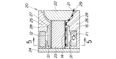
鋳造金型20は、溶湯注入ゲート21を含む固定キャビティ22と、固定キャビティ22の左方からセットしたボアピン23と、このボアピン23を取付けた抑え部材24と、上方からセットした第1スライドコア25と、下方からセットした第2スライドコア26とからなる部材である。そして、ボアピン23の周囲にシリンダライナー27を嵌め、シリンダライナー27の周囲に形成したキャビティ28に、本発明の中子12を配設し、溶湯注入ゲート21から溶湯の注入する状態である。図矢印29は溶湯の流れる湯回り方向を示す。
The
溶湯の湯回りは、溶湯注入ゲート21の配置とキャビティ22の断面形状とに大きく影響される。
中子の内側の面14は、時間当たりの流れる溶湯の流量が多いメイン通路に面しているため、外側の面15に比べて内側の面14に溶湯が流れ込み易く、溶湯の湯回りは、断面図の下側の中子12の内側の面14が、中子の外側の面15に比べ早いといえる。
The temperature of the molten metal is greatly influenced by the arrangement of the molten
Since the
この結果、溶湯は中子12の内側の面14により早く回るため、内側の面14と外側の面15とで溶湯が充填されるタイミングにずれが生ずる。
この結果、中子の一端31に図上から下向きに力F1がかかり、中子12の一端31は下側に変形する。
すなわち、85MPa〜100MPaという圧力で溶湯を注入する高圧鋳造において、溶湯圧力が中子12にかかり、中子12に変形が発生する場合がある。
As a result, since the molten metal rotates faster on the
As a result, a force F1 is applied to one
That is, in the high pressure casting in which the molten metal is injected at a pressure of 85 MPa to 100 MPa, the molten metal pressure is applied to the
図5は図4の5−5線断面図である。但し、第1スライドコア25と第2スライドコア26は省略した。
ST03において、高圧の溶湯が鋳造金型のキャビティに入り、中子12の一端31に下向きの力F1を受け、鋳造後の中子12の一端31に図下向きの変形量d1が発生したことを示す。
5 is a cross-sectional view taken along line 5-5 of FIG. However, the
In ST03, the high-pressure molten metal enters the cavity of the casting mold, receives the downward force F1 at one
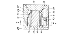
図6は予備ダイカスト鋳造(仮中子の変形反映後)を示す作用図であり、シリンダブロックの鋳造フロー図のST08を説明したものである。
高圧の溶湯が鋳造金型20のキャビティ28に入り、中子12の一端に図下向きに押し下げる力F2が加わる。この中子12は、変形を見込んだ見込み量δを反映した仮中子12である。
FIG. 6 is an operation diagram showing preliminary die casting (after reflecting the deformation of the temporary core), and explains ST08 in the casting flow diagram of the cylinder block.
The high-pressure molten metal enters the
図7は図6の7−7線断面図であり、変形反映後の仮中子12をキャビティ28内に配設し、予備ダイカスト鋳造をしたときの中子の変形d2を説明するものであり、図5において発生した仮中子の変形d1とを比較すると、d2≪d1と大幅に減らすことができることを示す。
あらかじめ、中子12の形状を設計上のウォータジャケット部の形状に対して、鋳造圧力の影響で変形する変形量を見込んだ歪な形状にしたので、シリンダブロック10内にウォータジャケット部11を精度良く形成することができる。
FIG. 7 is a cross-sectional view taken along line 7-7 in FIG. 6, and illustrates the deformation d2 of the core when the
Since the shape of the
図8は図1の別実施例図であり、鋳造圧力の影響により変形する変形量をあらかじめ見込んだ形状に造型したシリンダブロック鋳造用中子の形状を示す。
図において、原理を分かり易く説明するため、実際の形状よりも見込み角度θは大目に設定した。
FIG. 8 is a diagram of another embodiment of FIG. 1 and shows the shape of a cylinder block casting core formed into a shape that anticipates the amount of deformation deformed under the influence of casting pressure.
In the figure, in order to explain the principle in an easy-to-understand manner, the prospective angle θ is set larger than the actual shape.
鋳造金型のキャビティ内において、サイド巾木部13で鋳造時の中子12を支持する。中子は、シリンダの軸11に対し見込み角度θで鋳造金型のキャビティ内に配置する。
この見込み角度θは、中子造型に必要な抜き勾配θ1に鋳造圧力により変形する中子12の変量とは逆の向きにθ2だけ反映した角度である。
The core 12 at the time of casting is supported by the
This prospective angle θ is an angle reflected by a draft θ 1 necessary for core molding by θ 2 in the direction opposite to the variable of the core 12 deformed by casting pressure.
鋳造時に溶湯の圧力を中子12の内側の面14及び外側の面15に受けるが、鋳造金型の配設方向及び溶湯注入口の影響により、全体として中子12の内側の面14に溶湯圧力がかかる。キャビティの内部で、中子12を支持するのは、中子の他端41に備えるサイド巾木部13であり、中子の一端31に中子12の見込み角度θを減らす方向に力F3がかかる。
During casting, the pressure of the molten metal is applied to the
図9は図2の別実施例図であり、鋳造圧力の影響を受けた後のシリンダブロック鋳造用中子の形状を示す。
すなわち、鋳造金型のキャビティ内に配置した鋳造圧力を見込んだ形状に造型した中子は、溶湯による鋳造圧力を受け変形し、所定の形状のウオータジャケットを有するシリンダブロックを得ることができる。
FIG. 9 is a view of another embodiment of FIG. 2 and shows the shape of the cylinder block casting core after being affected by the casting pressure.
That is, the core formed in a shape that allows for the casting pressure disposed in the cavity of the casting mold is deformed by receiving the casting pressure from the molten metal, and a cylinder block having a water jacket having a predetermined shape can be obtained.
すなわち、中子12は、中子造型に必要な抜き勾配44(図8参照)を備えているが、この抜き勾配44を増減することで中子の変形量を見込んだ歪な形状に造型する。
中子12の歪な形状は、既存の抜き勾配44の角度θ1に変量分θ2を増減するだけであり、既存の抜き勾配44の角度θ1を変化させるだけで中子12に簡便に反映することができる。この結果、中子造型コストの高騰化を抑えることができる。
That is, the
The distorted shape of the core 12 can be simply reflected in the core 12 simply by changing the angle θ1 of the existing
図10は図3の別実施例図であり、図3のシリンダブロックの鋳造フロー図と異なる点は、ST06において、仮中子12の変形の算出結果を仮中子12の抜き勾配の増減に換算し、この抜き勾配の増減を反映した仮中子12を造型する工程を追加したという点であり、他は同じである。
FIG. 10 is a diagram of another embodiment of FIG. 3 and differs from the casting flow diagram of the cylinder block of FIG. 3 in that the calculation result of the deformation of the
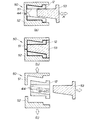
図11は仮中子の抜き勾配の増減を反映した仮中子を造型する造型フロー図であり、シリンダブロックの鋳造フロー図のST07を説明したものである。
(a)において、中子造型金型50は、第1中子造型ホルダ51と、このホルダ51に対向して配置する第2中子造型ホルダ52と、中子コア型53とから構成する部材である。
FIG. 11 is a molding flow diagram for molding a temporary core reflecting the increase and decrease of the draft angle of the temporary core, and explains ST07 of the casting flow diagram of the cylinder block.
In (a), the core molding die 50 includes a first
中子造型金型50の内部に造型砂54を充填し、第1中子造型ホルダ51と、第2中子造型ホルダ52とを図矢印A方向に摺動つつ、双方のホルダ51、52を合せ、鋳造圧力による変量を算出し、この変量から仮中子の抜き勾配の増減を反映した抜き勾配を有する中子12を造型する。
このとき、中子コア型53は所定の抜き勾配を有するので、中子成型後に抜くことができるため、中子の造型を行うことができる。
The core molding die 50 is filled with molding sand 54, and both the
At this time, since the
(b)において、第1中子造型ホルダ51と、第2中子造型ホルダ52と、中子コア型53とを合わせ所定の抜き勾配をもつ中子12を造型することを示す。
(c)において、第1中子造型ホルダ51と、第2中子造型ホルダ52と、中子コア型53とを外した状態であり、見込み角度θの中子12の造型が完了したことを示す。中子コア型53は所定の抜き勾配を有するので、成型後の中子12を抜くことができる。
In (b), the first
In (c), the first
中子12の歪な形状は、既存の抜き勾配に変量分を増減するだけで行える。
既存の抜き勾配を変化させるだけであり、中子12に簡便に反映することがでる。
この結果、中子造型コストの高騰化を抑えることができる。
The distorted shape of the core 12 can be achieved simply by increasing or decreasing the variable amount to the existing draft.
Only the existing draft angle is changed and can be easily reflected in the
As a result, an increase in core molding cost can be suppressed.
尚、請求項1において、鋳造圧力の影響で変形する変形量を見込んだ中子の歪な形状は、あらかじめ中子造型用の金型に反映する抜き勾配でなくても良い。
また、本発明のシリンダブロック鋳造用中子は、実施の形態ではクローズドデッキ形シリンダブロックに適用したが、セミクローズドデッキ形シリンダブロックにも適用可能であり、オープンデッキ形シリンダブロックに適用することは差し支えない。
In addition, in claim 1, the distorted shape of the core that anticipates the deformation amount that is deformed by the influence of the casting pressure may not be a draft that is reflected in advance on the mold for core molding.
In addition, the cylinder block casting core of the present invention is applied to a closed deck cylinder block in the embodiment, but can also be applied to a semi-closed deck cylinder block, and can be applied to an open deck cylinder block. There is no problem.
本発明のシリンダブロック鋳造用中子は、クローズドデッキ形シリンダブロックの鋳造に好適である。 The cylinder block casting core of the present invention is suitable for casting a closed deck type cylinder block.
10…シリンダブロック、11…ウォータジャケット部、12…中子、13…サイド巾木部、20…鋳造金型、31…中子の一端、41…中子の他端、44…抜き勾配、50…中子造型金型、見込み量…δ、見込み角度…θ。
DESCRIPTION OF
Claims (2)
この中子は、設計上のウォータジャケット部の形状に対して、鋳造圧力の影響で変形する変形量を見込んだ歪な形状にしたことを特徴とするシリンダブロック鋳造用中子。 In the casting core to be prepared to form the water jacket portion of the cylinder block,
The core for casting a cylinder block is characterized in that the core has a distorted shape that allows for a deformation amount that is deformed by the influence of casting pressure with respect to the shape of the designed water jacket portion.
2. The core for casting a cylinder block according to claim 1, wherein the core has a draft angle necessary for core molding and is formed into the distorted shape by increasing or decreasing the gradient.
Priority Applications (1)
| Application Number | Priority Date | Filing Date | Title |
|---|---|---|---|
| JP2004118928A JP2005297031A (en) | 2004-04-14 | 2004-04-14 | Cylinder block casting core |
Applications Claiming Priority (1)
| Application Number | Priority Date | Filing Date | Title |
|---|---|---|---|
| JP2004118928A JP2005297031A (en) | 2004-04-14 | 2004-04-14 | Cylinder block casting core |
Publications (1)
| Publication Number | Publication Date |
|---|---|
| JP2005297031A true JP2005297031A (en) | 2005-10-27 |
Family
ID=35329208
Family Applications (1)
| Application Number | Title | Priority Date | Filing Date |
|---|---|---|---|
| JP2004118928A Pending JP2005297031A (en) | 2004-04-14 | 2004-04-14 | Cylinder block casting core |
Country Status (1)
| Country | Link |
|---|---|
| JP (1) | JP2005297031A (en) |
Cited By (3)
| Publication number | Priority date | Publication date | Assignee | Title |
|---|---|---|---|---|
| CN102513511A (en) * | 2011-12-29 | 2012-06-27 | 南京飞燕活塞环股份有限公司 | Eccentric runner piston ring molding device |
| JP2015016477A (en) * | 2013-07-09 | 2015-01-29 | 本田技研工業株式会社 | Casting die apparatus and cylinder head casting method using the same |
| CN115464097A (en) * | 2022-09-22 | 2022-12-13 | 上海宝钢铸造有限公司 | Improved method for molding cooling wall cast-in bolt boss |
-
2004
- 2004-04-14 JP JP2004118928A patent/JP2005297031A/en active Pending
Cited By (4)
| Publication number | Priority date | Publication date | Assignee | Title |
|---|---|---|---|---|
| CN102513511A (en) * | 2011-12-29 | 2012-06-27 | 南京飞燕活塞环股份有限公司 | Eccentric runner piston ring molding device |
| CN102513511B (en) * | 2011-12-29 | 2013-08-28 | 南京飞燕活塞环股份有限公司 | Eccentric runner piston ring molding device |
| JP2015016477A (en) * | 2013-07-09 | 2015-01-29 | 本田技研工業株式会社 | Casting die apparatus and cylinder head casting method using the same |
| CN115464097A (en) * | 2022-09-22 | 2022-12-13 | 上海宝钢铸造有限公司 | Improved method for molding cooling wall cast-in bolt boss |
Similar Documents
| Publication | Publication Date | Title |
|---|---|---|
| EP2520385B1 (en) | Casting method and casting device for cast-metal object | |
| JP5659233B2 (en) | Unframed mold and its manufacturing method | |
| CN111659876A (en) | Process method for casting thin-wall aluminum alloy casting at low pressure | |
| CN102527939A (en) | Mold for gravity casting and gravity casting method using the mold | |
| CN105142821B (en) | Mold, clamp casting device, the manufacturing method of clamp and the clamp of clamp casting device | |
| CN101898237A (en) | Method for manufacturing metal mold and casting | |
| CN103328127A (en) | Interlock feature for railcar cores | |
| JP4619932B2 (en) | Body frame, die cast casting, die casting die, die casting method | |
| CA3014022C (en) | Method for forming dust-removal holes for a turbine blade and associated ceramic core | |
| CN104907521B (en) | Manufacturing process of middle frame of mobile phone | |
| JP2005297031A (en) | Cylinder block casting core | |
| JP5762488B2 (en) | Mold for casting | |
| CN107073563B (en) | Casting core, application of casting core and method of manufacturing casting core | |
| KR20100064910A (en) | A mold device for cylinder head casting | |
| JP4330422B2 (en) | Plate member to be cast, partition plate for intake port, sand core for forming intake port, and cylinder head | |
| KR100960268B1 (en) | A manufacturing method of vessel engine cylinder cover and maunfactured vessel engine cylinder cover thereof | |
| JP4687818B2 (en) | Semi-molten or semi-solid molding method | |
| JP4172371B2 (en) | Cylinder head manufacturing method | |
| JP7028343B2 (en) | Cylinder head manufacturing method | |
| JP4091808B2 (en) | Casting mold for vehicle wheel | |
| KR101610077B1 (en) | Core for gravity pressure casting | |
| CN110548835A (en) | Method for preventing cylinder cover from shrinkage porosity | |
| CN220943089U (en) | Sand mould for thin-wall disc castings | |
| US12343790B2 (en) | Assembly for producing a molding made of removable material of a turbomachine | |
| CN120901229A (en) | Feeding pouring system and method for I-shaped structural part of thin-wall ring casting |