JP2005297026A - Laser welding method for metal plate and metal plate for laser welding - Google Patents
Laser welding method for metal plate and metal plate for laser welding Download PDFInfo
- Publication number
- JP2005297026A JP2005297026A JP2004118309A JP2004118309A JP2005297026A JP 2005297026 A JP2005297026 A JP 2005297026A JP 2004118309 A JP2004118309 A JP 2004118309A JP 2004118309 A JP2004118309 A JP 2004118309A JP 2005297026 A JP2005297026 A JP 2005297026A
- Authority
- JP
- Japan
- Prior art keywords
- metal plate
- welding
- laser
- crank shape
- bent portion
- Prior art date
- Legal status (The legal status is an assumption and is not a legal conclusion. Google has not performed a legal analysis and makes no representation as to the accuracy of the status listed.)
- Pending
Links
Images


Landscapes
- Laser Beam Processing (AREA)
Abstract
【課題】 本発明は、亜鉛系めっき鋼板を含む金属板材を重ね溶接するレーザー溶接方法において、生産性や防錆性能を犠牲にすることなく、溶接欠陥が少なくかつ溶接部外観の優れたレーザー重ね溶接方法及びレーザー重ね溶接に適した金属板材を提供する。
【解決手段】 少なくとも亜鉛系めっき鋼板を含む金属板材を重ね溶接するレーザー溶接方法であって、少なくとも一つの金属板材に、溶接線に垂直な断面の形状が、合わせ面側に凹みのあるクランク形状であり、その凹みの溶接線上の最小深さ:Xa(mm)、最大深さ:Xb(mm)、薄い方の金属板板厚:Ya(mm)、照射面側の金属板板厚:Yb(mm)、重ね面の合計亜鉛付着量:Z(g/m2)とするとき、
Xa≧Z/(4800×Ya)
Xb≦0.35×Yb
とし、かつそのクランク形状の周辺における曲折が合わせ面側に凸となる角度である金属板材のレーザー溶接方法、及び、これに用いる金属板材及び溶接構造体である。
【選択図】 図3PROBLEM TO BE SOLVED: To provide a laser welding method for laminating and welding a metal plate material including a zinc-based plated steel sheet, with few welding defects and excellent weld appearance without sacrificing productivity and rust prevention performance. Provided is a metal plate material suitable for a welding method and laser lap welding.
A laser welding method in which a metal plate material including at least a zinc-based plated steel plate is lap welded, wherein at least one metal plate material has a cross-sectional shape perpendicular to the weld line and a crank shape having a dent on the mating surface side. The minimum depth on the weld line of the recess: Xa (mm), the maximum depth: Xb (mm), the thinner metal plate thickness: Ya (mm), the metal plate thickness on the irradiated surface side: Yb (Mm), when the total zinc adhesion amount on the overlapping surface is Z (g / m 2 ),
Xa ≧ Z / (4800 × Ya)
Xb ≦ 0.35 × Yb
And a metal plate material laser welding method in which the bending around the crank shape is an angle at which the bent surface is convex toward the mating surface side, and the metal plate material and welded structure used therefor.
[Selection] Figure 3
Description
本発明は、亜鉛系めっき鋼板を含む金属板材のレーザー重ね溶接方法及びレーザー重ね溶接用金属板材に関する。 The present invention relates to a laser lap welding method of a metal plate material including a galvanized steel sheet and a metal plate material for laser lap welding.
一般に、亜鉛系めっき鋼板は、自動車、家電、建材等、幅広い分野で使用されているが、長期間の防錆効果を確保する目的からは、厚目付けのめっきが有効である。特に、腐食環境が厳しい自動車用のめっき鋼板としては、めっき付着量40g/m2以上の厚目付け亜鉛系めっき鋼板が広く使用されている。亜鉛系めっきとしては、Zn中に微量のAlやその他不可避不純物を含有する純亜鉛系の溶融亜鉛めっき鋼板、Zn中にFeを5〜20%程度含有する合金化溶融亜鉛めっき鋼板、実質的にZn及び不可避不純物からなる電気亜鉛めっき鋼板、が主流である。 In general, galvanized steel sheets are used in a wide range of fields such as automobiles, home appliances, and building materials. For the purpose of ensuring a long-term rust prevention effect, thick plating is effective. In particular, as a plated steel sheet for automobiles having a severe corrosive environment, a thick-coated zinc-based plated steel sheet having a coating adhesion amount of 40 g / m 2 or more is widely used. As zinc-based plating, pure zinc-based hot-dip galvanized steel sheet containing a trace amount of Al and other inevitable impurities in Zn, alloyed hot-dip galvanized steel sheet containing about 5 to 20% Fe in Zn, Electrogalvanized steel sheets made of Zn and inevitable impurities are the mainstream.
しかし、これらの亜鉛系めっき鋼板は、総じて溶接性が劣るという難点がある。溶接性は、溶接方法と密接な関係があるが、レーザー重ね溶接においても、亜鉛系めっき鋼板は溶接性が劣るという課題がある。ここで、レーザー重ね溶接とは、2枚あるいはそれ以上の金属板を重ね、金属板表面にほぼ垂直な方向からレーザービームを照射して、キーホール溶接する方法をいう。亜鉛系めっき鋼板を含む金属板のレーザー重ね溶接では、2枚の金属板の間に存在するめっき金属がレーザービームで加熱され、亜鉛が溶融・気化して蒸発し、この亜鉛蒸気の圧力によって、溶融池の溶融金属がスパッタとして吹き飛ばされて、ビードを貫通する欠陥(ピット)を生じたり、亜鉛蒸気が溶融金属中に閉じ込められて凝固することによる、ブローホールを生じたり、といった欠陥が多発する。従って、亜鉛系めっき鋼板を含む金属板材を高品質にレーザー重ね溶接することは困難であった。 However, these galvanized steel sheets have a drawback that the weldability is generally poor. Although the weldability is closely related to the welding method, there is a problem that the galvanized steel sheet has poor weldability even in laser lap welding. Here, laser lap welding refers to a method in which two or more metal plates are overlapped, and a laser beam is irradiated from a direction substantially perpendicular to the surface of the metal plate to perform keyhole welding. In laser lap welding of metal plates including galvanized steel sheets, the plating metal existing between the two metal plates is heated with a laser beam, and the zinc melts and vaporizes and evaporates. The molten metal is blown off as spatter, and defects such as defects (pits) penetrating the beads are generated, or blow holes are generated due to the zinc vapor confined and solidified in the molten metal. Therefore, it has been difficult to laser-lap weld a metal plate material including a zinc-based plated steel plate with high quality.
かかるレーザー重ね溶接における課題を解決する手段として、例えば、以下の技術が提案されている。前処理工程で予め亜鉛系めっきを加熱して除去した後に、レーザー重ね溶接する方法{特開平4−321190号公報(特許文献1)参照}。亜鉛系めっきが存在しなければ本課題は生じないので、効果としては有効であるが、この方法では、工程が2つ以上必要であり、生産性及びコストの点で課題がある。予めめっき鋼板の重ね面にレーザーを吸収する材料を塗布しておく方法{特開平3−165994号公報(特許文献2)参照}。この方法においても、工程が2つ以上必要である。 As means for solving such problems in laser lap welding, for example, the following techniques have been proposed. A method of laser lap welding after heating and removing zinc-based plating in advance in the pretreatment step {refer to Japanese Patent Laid-Open No. 4-321190 (Patent Document 1)}. Since this problem does not occur unless zinc-based plating exists, this method is effective as an effect, but this method requires two or more steps, and there are problems in terms of productivity and cost. A method in which a material that absorbs laser is applied in advance to the overlapping surface of plated steel sheets {see Japanese Patent Laid-Open No. 3-165994 (Patent Document 2)}. Also in this method, two or more steps are necessary.
Zn−Ni系合金めっき鋼板のめっき付着量と鋼板板厚との関係を限定することで、レーザー溶接における溶接欠陥が少なく、かつ溶接部外観の優れたZn−Ni系合金めっき鋼板{特許第3139325号公報(特許文献3)参照}。これは、溶接部に悪影響を及ぼす亜鉛の量に下限があり、それ以下に亜鉛量を制限するという点では妥当であるが、この技術では、例えば、板厚が0.6mmではめっき付着量を15g/m2以下としなければならず、亜鉛系めっき鋼板の最大の機能である耐食性が犠牲となり、厳しい腐食環境で長期間使用される自動車等では耐久性が確保できない、という難点がある。 By limiting the relationship between the coating amount of the Zn-Ni alloy-plated steel sheet and the thickness of the steel sheet, there are few welding defects in laser welding, and the Zn-Ni alloy-plated steel sheet with superior weld appearance {Japanese Patent No. 3139325 Issue gazette (patent document 3)}. This is reasonable in that there is a lower limit to the amount of zinc that adversely affects the weld, and the amount of zinc is limited below that. However, with this technique, for example, if the plate thickness is 0.6 mm, the amount of plating adhesion is reduced. 15 g / m 2 or less is required, and the corrosion resistance, which is the maximum function of the galvanized steel sheet, is sacrificed, and there is a problem that durability cannot be ensured in an automobile or the like used for a long time in a severe corrosive environment.
一方、レーザー溶接される鋼板の間に隙間を設けることにより、蒸発する亜鉛を逃がして良好な溶接性を得る方法も、いくつか報告されている(特許文献4〜8参照)。しかし、これらはいずれも、溶接される鋼板の間の鋼板上に凸部を設けることにより、鋼板間に隙間を確保する方法である。隙間の最小値を凸部の高さにより制御するのであるが、凸部では、鋼板が接触するので、実際には設定した凸部より離れた個所を溶接しなければならない。そのため、折角凸部を制御良く設定出来ても、押さえ方や板の変形により、実際の隙間の大きさは、本来設定したかった大きさと変わってしまう可能性がある。また、元々、金属板に微小な凸部を成形するのは、凹部を成形するより困難である。
On the other hand, several methods have also been reported for obtaining good weldability by releasing evaporated zinc by providing a gap between steel plates to be laser welded (see
鋼板の隙間を制御するレーザー溶接方法として、鋼板のどちらか一方に、溶接線に沿った溝状のガス抜き部を形成してから、溶接する方法が開示されている{特開平4−327385号公報(特許文献9)参照}。この方法はガス抜き部以外を密着させることで、設定した隙間量を制御できる点は優れているが、ガス抜き部を予定する溶接線に沿って形成する方法、及び、その形成したガス抜き部に沿って実際にレーザー溶接する方法に困難があり、例えば、複雑な部品形状の周囲を複雑な曲線の溶接線を持って溶接するような場合、そのガス抜き部形成及びそのガス抜き部に沿った溶接のいずれにも、加工上や制御上の困難があり、実現できてもコスト高になる、生産性が悪くなると言う問題点があった。 As a laser welding method for controlling the gap between steel plates, a method is disclosed in which a groove-like gas vent portion along the weld line is formed on one of the steel plates and then welded {Japanese Patent Laid-Open No. 4-327385. Gazette (patent document 9)}. Although this method is excellent in that the set gap amount can be controlled by sticking other than the gas vent part, the method of forming the gas vent part along the planned weld line, and the formed gas vent part For example, in the case of welding around a complicated part shape with a complicated curved welding line, the formation of the gas vent part and the gas vent part along the gas vent part are difficult. Both of these weldings have problems in processing and control, and even if they can be realized, there is a problem that costs are increased and productivity is deteriorated.
本発明が解決しようとする課題は、亜鉛系めっき鋼板を含む金属板材を重ね溶接するレーザー溶接方法において、生産性や防錆性能を犠牲にすることなく、溶接欠陥が少なく、かつ、溶接部外観の優れたレーザー重ね溶接方法及びレーザー重ね溶接に適した金属板材を提供することにある。 The problem to be solved by the present invention is a laser welding method in which a metal plate material including a zinc-based plated steel sheet is lap welded, without sacrificing productivity and rust prevention performance, with few welding defects, and the appearance of the welded portion. An excellent laser lap welding method and a metal plate material suitable for laser lap welding.
本発明者らは、レーザー重ね溶接による亜鉛系めっき鋼板の溶接継ぎ手部について、溶接欠陥を低減し、優れた溶接部外観と継ぎ手強度を確保するための溶接方法及びそれに適した鋼板について、種々の検討と実験を続けた結果、ついに、簡便で低コストな方法で鋼板間の隙間を制御し、溶接欠陥を低減し、優れた溶接部外観と継ぎ手強度を確保できる溶接方法を見出した。 The inventors of the present invention have various welding methods and steel plates suitable for welding joints of galvanized steel sheets by laser lap welding to reduce welding defects and ensure excellent weld appearance and joint strength. As a result of continuous examination and experimentation, the inventors finally found a welding method that can control the gaps between steel plates by a simple and low-cost method, reduce welding defects, and ensure excellent weld joint appearance and joint strength.
本発明は、こうした知見に基づいてなされたもので、その要旨とするところは、以下のとおりである。
(1)少なくとも一方が亜鉛系めっき鋼板である金属板材同士を重ね溶接するレーザー溶接方法であって、該金属板材の一方の金属板材に屈曲部を形成し、重ね合わされる金属板材の間に該屈曲部による隙間を保持して、該屈曲部に沿ってレーザー溶接する際に、該屈曲部の溶接線に垂直な断面の形状が、合わせ面側に凹みのあるクランク形状であり、その凹みの溶接線上の最小深さをXa(mm)、最大深さをXb(mm)、前記金属板材の薄い方の板厚をYa(mm)、レーザー照射面側の金属板板厚をYb(mm)、重ね面の合計亜鉛付着量をZ(g/m2)とするとき、
Xa≧Z/(4800×Ya)
Xb≦0.35×Yb
の条件を満足し、かつそのクランク形状の周辺における曲折が合わせ面側に凸となる角度とすることを特徴とする金属板材のレーザー溶接方法。
The present invention has been made based on such findings, and the gist thereof is as follows.
(1) A laser welding method in which at least one is a galvanized steel sheet and is welded to each other, wherein a bent portion is formed on one metal sheet of the metal sheet, and the metal sheet is overlapped between the metal sheets When laser welding is performed along the bent portion while maintaining a gap due to the bent portion, the shape of the cross section perpendicular to the weld line of the bent portion is a crank shape having a dent on the mating surface side. The minimum depth on the weld line is Xa (mm), the maximum depth is Xb (mm), the thin plate thickness of the metal plate is Ya (mm), and the metal plate thickness on the laser irradiation surface side is Yb (mm) When the total zinc adhesion amount on the overlapping surface is Z (g / m 2 ),
Xa ≧ Z / (4800 × Ya)
Xb ≦ 0.35 × Yb
A metal plate material laser welding method characterized by satisfying the above condition and having an angle at which the bend around the crank shape is convex toward the mating surface.
(2)亜鉛系めっき鋼板を含む金属板材の重ねレーザー溶接に供される金属板材であって、重ね合わせた時にレーザー溶接される部分の金属板材の間に隙間を保持するための屈曲部が形成されており、該屈曲部の溶接線に垂直な断面の形状が、合わせ面側に凹みのあるクランク形状で、その凹みの中心線上の最小深さ:Xa(mm)、最大深さ:Xb(mm)とするとき、
Xa≧0.05
Xb≦0.2
であり、かつそのクランク形状の周辺における曲折が合わせ面側に凸となる角度であることを特徴とするレーザー溶接用金属板材。
(2) A metal plate material that is subjected to overlap laser welding of a metal plate material including a zinc-based plated steel plate, and a bent portion is formed to hold a gap between the metal plate materials of the portion that is laser-welded when overlapped The shape of the cross section perpendicular to the weld line of the bent portion is a crank shape having a dent on the mating surface side, and the minimum depth on the center line of the dent: Xa (mm), the maximum depth: Xb ( mm)
Xa ≧ 0.05
Xb ≦ 0.2
A metal plate material for laser welding, characterized in that the bending around the crank shape is an angle that protrudes toward the mating surface.
(3)少なくとも一方が亜鉛系めっき鋼板である金属板材同士を重ね溶接したレーザー溶接構造体であって、該金属板材の一方の金属板材に屈曲部が形成されており、重ね合わされた金属板材の間に該屈曲部による隙間を有し、該屈曲部の溶接線に垂直な断面の形状が、合わせ面側に凹みのあるクランク形状であり、溶接後のクランク形状の両側の側壁から計算される溶接線上の凹み深さが、その最小深さをXa(mm)、最大深さをXb(mm)、前記金属板材の薄い方の板厚をYa(mm)、レーザー照射面側の金属板板厚をYb(mm)、重ね面の合計亜鉛付着量をZ(g/m2)とするとき、
Xa≧Z/(4800×Ya)
Xb≦0.35×Yb
の条件を満足し、かつそのクランク形状の周辺における曲折が合わせ面側に凸となる角度であることを特徴とするレーザー溶接構造体である。
(3) A laser welded structure in which at least one is a galvanized steel sheet and is welded to each other, wherein a bent portion is formed on one of the metal sheets, and the stacked metal sheets The shape of the cross section perpendicular to the weld line of the bent portion with a gap due to the bent portion is a crank shape having a depression on the mating surface side, and is calculated from the side walls on both sides of the crank shape after welding. The depth of the recess on the weld line is Xa (mm) as the minimum depth, Xb (mm) as the maximum depth, Ya (mm) as the thin plate thickness of the metal plate, and the metal plate on the laser irradiation surface side. When the thickness is Yb (mm) and the total zinc adhesion amount on the overlap surface is Z (g / m 2 ),
Xa ≧ Z / (4800 × Ya)
Xb ≦ 0.35 × Yb
The laser welded structure is characterized in that the above-mentioned condition is satisfied and the bend in the periphery of the crank shape is an angle that protrudes toward the mating surface.
本発明のレーザー溶接方法及びレーザー溶接用金属板材は、低コストかつ生産性良く、健全で信頼性の高いレーザー重ね溶接部を提供するものである。これは自動車、建築・住宅、家電等に広く適用することが可能で、高効率な溶接方法と、溶接部の高い信頼性を両立することにより産業の発展に大きく寄与するものである。 The laser welding method and the metal sheet for laser welding according to the present invention provide a laser lap weld with low cost, good productivity, and high reliability. This can be widely applied to automobiles, architecture / housing, home appliances, etc., and contributes greatly to the development of the industry by achieving both a highly efficient welding method and high reliability of the welded part.
以下、本発明を詳細に説明する。
発明者らは、種々のめっき鋼板、具体的には、めっき種としては、溶融亜鉛めっき鋼板、合金化溶融亜鉛めっき鋼板、電気Znめっき鋼板、Zn−Ni合金電気めっき鋼板、Zn−Fe合金電気めっき鋼板等の亜鉛系めっき鋼板で、めっき付着量としては、片面あたり20〜80g/m2、板厚としては、0.7〜2.3mmの鋼板を用い、種々の溶接条件でレーザー重ね溶接実験を行い、溶接部外観とスパッタ発生量を調べた。ここで、スパッタ発生量は、溶接前後の試験片質量の減少量として求めたものであり、レーザー重ね溶接によって蒸発した金属や溶接線以外の部分に飛散した金属の量の合計に相当する。
Hereinafter, the present invention will be described in detail.
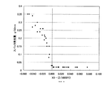
The inventors have made various plated steel sheets, specifically, galvanized steel sheets, galvannealed steel sheets, galvannealed steel sheets, Zn electroplated steel sheets, Zn—Ni alloy electroplated steel sheets, Zn—Fe alloy electroplated steels. It is a zinc-plated steel sheet such as a plated steel sheet. The plating adhesion amount is 20 to 80 g / m 2 per side, and the plate thickness is 0.7 to 2.3 mm. Laser lap welding is performed under various welding conditions. An experiment was conducted to examine the appearance of the weld and the amount of spatter generated. Here, the spatter generation amount is obtained as a reduction amount of the test piece mass before and after welding, and corresponds to the total amount of metal evaporated by laser lap welding and metal scattered on portions other than the weld line.
スパッタ発生量が増加するのに従って、溶接部に存在する金属量が減少し、溶接継ぎ手の信頼性が低下するが、発明者らが別途調べた結果では、スパッタ発生量が溶接部溶融金属量のおよそ20%以下であれば、溶接継ぎ手部の継ぎ手強度は母材とほぼ同等であり、この範囲であれば継ぎ手の信頼性が確保できると考えられる。溶接部が全く健全な場合でも、母材及びめっきの一部が蒸発するので、試験片質量の減少量は0にはならない。 As the amount of spatter generated increases, the amount of metal present in the weld decreases and the reliability of the weld joint decreases, but the results of separate investigations by the inventors indicate that the amount of spatter generated is the amount of molten metal in the weld. If it is about 20% or less, the joint strength of the welded joint portion is almost the same as that of the base material, and it is considered that the reliability of the joint can be secured within this range. Even when the welded part is completely healthy, the base material and a part of the plating are evaporated, so the amount of decrease in the test piece mass is not zero.
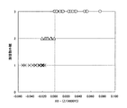
数多くの実験結果について整理した結果、健全な溶接部を得るための条件は、2枚の鋼板の重ね合わせ面での「隙間」と「鋼板板厚」と重ね合わせ面での亜鉛の「合計付着量」の3者と非常に密接な関係があることを明らかにした。特に、健全な溶接部を得るために重要な条件は、従来から言われているようなめっき層全体の付着量ではなく、めっき層中の亜鉛の合計付着量が非常に重要であること、さらに、同じ板厚の2枚の鋼板の重ね合わせ面の隙間をX(mm)、鋼板板厚をY(mm)、重ね合わせ面の亜鉛の合計付着量をZ(g/m2)とした時、X≧Z/(4800×Y) … (1)
を満足すると、図1及び図2に示すように、溶接部外観が顕著に向上し、スパッタ発生量が格段に低減できることを見出した。
As a result of arranging a large number of experimental results, the conditions for obtaining a sound weld are the “gap” and “steel plate thickness” on the overlapping surface of two steel plates and the “total adhesion of zinc on the overlapping surface” It was clarified that there is a very close relationship with the three "quantity". In particular, the important condition for obtaining a sound weld is that the total amount of zinc in the plating layer is very important, not the amount of adhesion of the entire plating layer as conventionally said, When the gap between the overlapping surfaces of two steel plates with the same thickness is X (mm), the steel plate thickness is Y (mm), and the total adhesion amount of zinc on the overlapping surfaces is Z (g / m 2 ) , X ≧ Z / (4800 × Y) (1)
When satisfied, as shown in FIG. 1 and FIG. 2, it was found that the appearance of the welded portion was remarkably improved and the amount of spatter generated could be significantly reduced.
なお、異なる厚さの鋼板を同様に溶接する場合には、薄い方の鋼板板厚をYとすれば同じ結果が得られた。一方、隙間が開きすぎると、溶接金属が不足し、溶け落ち不良が生ずる。これに対しては、同様に、同じ板厚の2枚の鋼板の重ね合わせ面の隙間をX(mm)、照射面側の鋼板板厚をY(mm)とした時、X≦0.35×Y … (2)
を満足すれば、溶け落ち不良が生じないことを見いだした。なお、亜鉛めっき鋼板と、アルミニウム板や銅板等の他の金属板との接合においても、式(1)及び式(2)の関係は変わらなかった。
In addition, when welding the steel plate of different thickness similarly, the same result was obtained if the thinner steel plate thickness was set to Y. On the other hand, if the gap is too wide, the weld metal is insufficient, resulting in poor melting. For this, similarly, when the gap between the overlapping surfaces of two steel plates having the same thickness is X (mm) and the steel plate thickness on the irradiation surface side is Y (mm), X ≦ 0.35 × Y (2)
It was found that if the above is satisfied, there will be no burn-out defect. In addition, in the joining of the galvanized steel sheet and other metal plates such as an aluminum plate and a copper plate, the relationship of the formula (1) and the formula (2) was not changed.
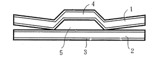
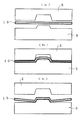
このように、重ね合わせ面に一定の隙間を設けることが、亜鉛めっき鋼板を含む金属板のレーザー重ね溶接には重要であるが、金属板間に一定の隙間を確保することは、例えば、工場のラインで、ロボットにより部品をレーザー溶接して行くような場合には難しい。そこで、本発明者らは、図3にその模式図を示すように、金属板の断面形状に、合わせ面側に凹みとなるような微小なクランク形状を与え、このクランク形状の凹み部で金属板間に一定の隙間を実現することを発明した。図3〜5の模式図では、クランク形状を強調するために誇張しているが、実際にはその凹みは金属板の厚みよりも小さい。 Thus, it is important for laser lap welding of a metal plate including a galvanized steel sheet to provide a certain gap on the overlapping surface, but ensuring a certain gap between the metal sheets is, for example, a factory This is difficult when the parts are laser welded by a robot. Therefore, as shown in the schematic diagram of FIG. 3, the present inventors give the cross-sectional shape of the metal plate a minute crank shape that becomes a recess on the mating surface side, and the crank-shaped recess has a metal Invented the realization of a certain gap between the plates. 3 to 5 are exaggerated to emphasize the crank shape, but the dent is actually smaller than the thickness of the metal plate.
金属板の断面に微小なクランク形状を与えるには、例えば、凸部を持つ金型と凹部を持つ金型で挟んでプレス加工すればよく、容易にかつ再現性良く一定のクランク形状をもったレーザー溶接用のめっき鋼板を成型できる。ただし、後述の実施例でも紹介するように、クランクの凹部の深さは、0.1mmオーダーの微小なものであるため、前記の凸金型と凹金型におけるクリアランスは最小限にする必要がある。クリアランスを大きく取りすぎると、全体として弾性変形範囲になってしまい、成形ができなくなる。具体的には、実施例の中では、凹部の深さの半分から倍程度のクリアランスを採用すると良い。ここで、クリアランスとは、凸金型の凸部幅と凹金型の凹部幅の差から、成形する板厚を引いた値を示す。 In order to give a minute crank shape to the cross section of the metal plate, for example, it is only necessary to press and hold it between a mold having a convex part and a mold having a concave part, and it has a constant crank shape easily and reproducibly. Can form plated steel sheets for laser welding. However, since the depth of the concave portion of the crank is a minute one on the order of 0.1 mm, as will be introduced in the examples described later, the clearance between the convex mold and the concave mold must be minimized. is there. If the clearance is too large, the entire range will be in the elastic deformation range and molding will not be possible. Specifically, in the embodiment, it is preferable to employ a clearance that is about half to twice the depth of the recess. Here, the clearance indicates a value obtained by subtracting the plate thickness to be molded from the difference between the convex width of the convex mold and the concave width of the concave mold.
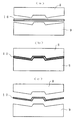
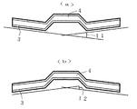
クランク形状が形成された金属板を、溶接時にクランク形状の周囲が密着するよう保持すれば、クランクの凹みにより一定の隙間を保持できるため、制御された隙間量の実現が非常に容易である。特に、クランク形状周囲の曲折を合わせ面側に凸にすると、部材を溶接のために押しつけた時に、クランク部近傍が必ず最初に接触するので、溶接部には一定の隙間を確保しながら、かつ溶け落ちる様な過大な隙間を生じることが無くなる(図4参照)。 If the metal plate formed with the crank shape is held so that the periphery of the crank shape is in close contact during welding, a constant gap can be held by the depression of the crank, so that it is very easy to realize a controlled gap amount. In particular, if the bending around the crank shape is convex on the mating surface side, when the member is pressed for welding, the vicinity of the crank part always comes into contact first, so ensuring a certain gap in the welded part, and An excessive gap that melts away is eliminated (see FIG. 4).
このクランク形状周辺の曲折は、どんなに微小でも合わせ面側に凸でありさえすれば、最初に溶接部周辺が接触する状況を実現できるが、明確に凸にしておきたい場合には、図8で示した角度11を0.1°以上に設定して成型をすれば良い。ただし、2°以上の大きな角度設定は、通常隙間が過大になり過ぎるので好ましくない。逆に、クランク周辺の曲折が、合わせ面側に凹であると(図5参照)、設定したい隙間以上に隙間が開く可能性があり、溶け落ちによる溶接部不良が発生し易くなるため、望ましくない。 As long as the bend around the crank shape is convex to the mating surface, no matter how small the bend is, the situation where the periphery of the welded portion first contacts can be realized. The shown angle 11 may be set to 0.1 ° or more for molding. However, a large angle setting of 2 ° or more is not preferable because the gap is usually excessive. On the contrary, if the bending around the crank is concave on the mating surface side (see FIG. 5), there is a possibility that a gap may be opened beyond the gap to be set, and it is easy to cause a weld defect due to melting, which is desirable. Absent.
クランク断面周囲において合わせ面側に凸の曲折を成型するには、クランク断面を成型する凹凸の金型自体に設定した角度を付けておいて成型する方法も考えられる(図6参照)が、金型の凹側の深さを凸側の高さより大きくすれば、凹凸の周囲の面が接触した時点で凹みの底で板が拘束されず、弾性的な歪みを保持しており、これが成型終了時にクランクの側面を開く方向にスプリングバックして合わせ面側に凸となる角度を実現する事ができる(図7参照)。なお、図6(a)、図7(a)はプレス前、図6(b)、図7(b)はプレス中、図6(c)、図7(c)はプレス後をそれぞれ示す。 In order to mold a convex bend on the mating surface side around the crank cross section, a method of forming the crank section with an angle set on the concave and convex mold itself can be considered (see FIG. 6). If the depth of the concave side of the mold is made larger than the height of the convex side, the plate is not restrained at the bottom of the recess when the surface around the unevenness comes into contact, and elastic deformation is maintained, which is the end of molding Sometimes it is possible to achieve an angle that protrudes toward the mating surface by springback in the direction of opening the side of the crank (see FIG. 7). 6 (a) and 7 (a) show before pressing, FIGS. 6 (b) and 7 (b) show during pressing, and FIGS. 6 (c) and 7 (c) show after pressing.
このような効果を得るためには、金型の凹側深さの値が凸側高さの値より50μm以上と十分に大きければ、十分にスプリングバックが生じて、好ましい角度を成形できるが、凹深さの値はどんなに深くても、材料の形状はほぼ凸高さで決まるため、その上限は特になく、金型製造上、精度の要らない安価な加工法を適用できる。 In order to obtain such an effect, if the concave side depth value of the mold is sufficiently larger than the convex side height value by 50 μm or more, sufficient springback occurs, and a preferable angle can be formed. No matter how deep the concave depth value is, the shape of the material is almost determined by the convex height, so there is no particular upper limit, and an inexpensive processing method that does not require precision can be applied for mold manufacture.
クランク成形部のサイズは、凹み部の深さに関しては、前述の板間の亜鉛合計量と金属板材の薄い方の板厚により定まる必要最小隙間量より深く、かつ、溶け落ちないようにレーザー照射面側の板厚の35%以下の浅さとする必要がある。そのため、凹み部の溶接線上の最小深さ:Xa(mm)及び最大深さ:Xb(mm)を、薄い方の金属板板厚:Ya(mm)、照射面側の金属板板厚:Yb(mm)、重ね面の合計亜鉛付着量:Z(g/m2)に対して、
Xa≧Z/(4800×Ya) … (3)
Xb≦0.35×Yb … (4)
となるように成形、管理する。
As for the size of the crank forming part, the depth of the dent part is deeper than the necessary minimum gap amount determined by the total amount of zinc between the above-mentioned plates and the thickness of the thin metal plate, and laser irradiation so as not to melt off. It is necessary to set the depth to 35% or less of the plate thickness on the surface side. Therefore, the minimum depth on the weld line of the dent: Xa (mm) and the maximum depth: Xb (mm), the thinner metal plate thickness: Ya (mm), the metal plate thickness on the irradiated surface side: Yb (Mm), the total zinc adhesion amount on the overlapping surface: Z (g / m 2 )
Xa ≧ Z / (4800 × Ya) (3)
Xb ≦ 0.35 × Yb (4)
Form and manage so that
相手の鋼板が明らかでない時は、それぞれの値を
Xa≧0.05 … (5)
Xb≦0.2 … (6)
となるように成形、管理すれば、ほとんどの場合をカバーできる。相手の鋼板が明らかでない時は、溶接される部分も明らかでないこともあるので、この場合は、溶接線を凹み部の中心線と仮定して、中心線における凹み部の最小深さをXa、最大深さをXbとすれば良い。このようなクランク形状においては、その中心線を溶接することで、安定して最大の効果が期待できるからである。
When the mating steel plate is not clear, set each value to Xa ≧ 0.05 (5)
Xb ≦ 0.2 (6)
If it is formed and managed so that it becomes, most cases can be covered. When the mating steel plate is not clear, the welded part may not be clear. In this case, assuming that the weld line is the center line of the recess, the minimum depth of the recess in the center line is Xa, The maximum depth may be Xb. This is because, in such a crank shape, the maximum effect can be expected stably by welding the center line.
ここで、凹み部の中心線とは、断面のクランク形状の4つの屈曲点を台形の頂点と考え、両端の屈曲点を結ぶ線を底辺としたときの底辺の中心を、クランク形状の延長方向に連続させた線であり、その深さは、底辺の中心を通り底辺に垂直な線で計測される深さとする。図9に、一断面例における深さの定義を模式図で示した。図9のように、左右非対称のクランク形状であっても本発明の範疇であり、その場合の深さは、溶接線が決められていれば、その部位においての深さを、溶接線が決められていなければ、図9の如く凹み部の中心の深さとする。 Here, the center line of the dent is considered to be the trapezoidal apex of the four bending points of the crank shape of the cross section, and the center of the base when the line connecting the bending points at both ends is the base, the extension direction of the crank shape The depth is the depth measured by a line passing through the center of the base and perpendicular to the base. FIG. 9 is a schematic diagram showing the definition of depth in one cross-sectional example. As shown in FIG. 9, even a left-right asymmetric crank shape is within the scope of the present invention. In this case, if the weld line is determined, the weld line determines the depth at that portion. If not, the depth is set at the center of the recess as shown in FIG.
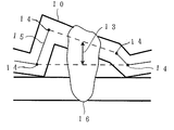
現実のプレス品では、屈曲部は純粋に幾何学的な頂点にはならないが、前後の板厚中心あるいは板表面を直線と近似して、その延長線の交点を屈曲点と定義すれば、屈曲点が求められ、4つの屈曲点から凹み部の深さを決定できる。溶接後の溶接構造体では、溶接時の熱影響により若干の板変形が生じている可能性があるが、前述と同様に、屈曲している部分の近傍の平面部から延長線を延ばして屈曲点を定義すれば、溶接ビード周辺の歪みにとらわれずに、凹み部の深さが推定可能である。すなわち、溶接後のクランク形状の両側の側壁から計算される溶接線上の凹みの深さを、図10で示したように、溶接ビードの両側に残されるクランク形状の側壁の左右合計4つの屈曲点より、幾何学的に求めた深さと定義すればよい。 In an actual press product, the bent part does not have a purely geometric apex, but if the front and rear plate thickness centers or the plate surface are approximated to a straight line and the intersection of the extension lines is defined as the bent point, the bent part A point is determined, and the depth of the recess can be determined from the four bending points. In the welded structure after welding, there is a possibility that some plate deformation has occurred due to the thermal effect during welding, but as described above, the extension line is extended from the flat part near the bent part and bent. If the point is defined, the depth of the recess can be estimated without being bound by the distortion around the weld bead. That is, the depth of the dent on the weld line calculated from the side walls on both sides of the crank shape after welding, as shown in FIG. 10, is a total of four bending points on the left and right sides of the crank shape side walls left on both sides of the weld bead. Therefore, it may be defined as a geometrically determined depth.
さらに具体的には、4つの屈曲点を最初と最後の屈曲点がX軸上にあり、中間の二つの屈曲点がYの値で正の側にあるように座標軸を取って、最初から4つの屈曲点をそれぞれ、(A,0)、(C,D)、(E,F)、(B,O)の座標とし、溶接中心線を(G,O)を通るY軸に平行な直線とする。ここで、A>Bと座標を取る。この時、「溶接後のクランク形状の両側の側壁から計算される溶接線上の凹み深さ」をHとすると、Hは次式で計算できる。
H={D×(E−G)+F×(G−C)/(E−C)}
式にはA、Bの値が現れないが、これは座標軸をそのように取ったためである。
More specifically, the coordinate axes are taken so that the first and last inflection points are on the X axis and the middle two inflection points are on the positive side in the Y value. A straight line parallel to the Y axis passing through (G, O) with the bending center as the coordinates of (A, 0), (C, D), (E, F), and (B, O). And Here, A> B and coordinates are taken. At this time, if “the dent depth on the weld line calculated from the sidewalls on both sides of the crank shape after welding” is H, H can be calculated by the following equation.
H = {D × (EG) + F × (GC) / (EC)}
Although the values of A and B do not appear in the formula, this is because the coordinate axes are taken as such.
凹み部の幅に関しては、溶接ビードの倍程度の大きさがあれば効果があることを見いだしており、これより広くする必要がある。溶接する板材が十分な強度があり、溶接時の押さえ等による変形が無視できるならば、形状として問題がない限り、その幅には特に制限を設けないが、軟鋼の薄板等で、変形が無視できない場合は、せいぜい10mm幅程度にしておくと良い。 With regard to the width of the recess, it has been found that there is an effect if it is about twice the size of the weld bead, and it is necessary to make it wider than this. If the plate to be welded has sufficient strength and deformation due to pressing during welding is negligible, there is no particular restriction on the width unless there is a problem with the shape. If this is not possible, it should be at most 10 mm wide.
金属板材のクランク形状は、レーザー溶接前に形成されていれば良く、特に形成時期を限定するものではない。例えば、金属板段階であっても良いし、金属板を部品形状に成形する途中の工程であっても良く、あるいは部品形状に成形した後でレーザー重ね溶接する前であっても良く、いずれも効果が発揮される。ただし、実用上は、プレス加工を受ける部材であれば、プレス時に同時に加工しておくのが効率的である。 The crank shape of the metal plate material is not particularly limited as long as it is formed before laser welding. For example, it may be a metal plate stage, a process in the middle of forming a metal plate into a part shape, or after forming into a part shape and before laser lap welding. The effect is demonstrated. However, practically, if the member is subjected to press working, it is efficient to work at the same time as pressing.
本発明が対象とする亜鉛系めっき鋼板は、亜鉛又は亜鉛を主体とする合金を鋼板表面(両面又は片面)にめっきしたものであり、製法は、工業的には溶融めっき、電気めっきが主流であるが、蒸着めっき等の他の製造方法であっても、もちろん構わない。亜鉛系めっき鋼板の鋼板母材は、通常自動車その他の製品に使われる鋼板であれば、すべて本発明の対象であり、特に鋼板の組成・組織・強度・延性等を限定するものではない。 The zinc-based plated steel sheet targeted by the present invention is obtained by plating zinc or an alloy mainly composed of zinc on the surface (both sides or one side) of the steel sheet. Of course, other manufacturing methods such as vapor deposition may be used. The steel plate base material of the galvanized steel plate is a subject of the present invention as long as it is a steel plate usually used for automobiles and other products, and does not particularly limit the composition, structure, strength, ductility, etc. of the steel plate.
なお、本発明の溶接方法においては、上記めっき鋼板のめっき面が、重ね合わせ部の重ね合わせ面側に少なくとも存在するものである。また、亜鉛系めっき鋼板とレーザー溶接する相手材は、亜鉛系めっき鋼板である必要はなく、めっきのない鋼板や他の金属板であっても良い。また、前述のクランク形状は、必ずしも亜鉛系めっき鋼板に設ける必要はなく、 重ね合わせをする相手材の金属板に設けてあっても良い。その目的が適正な隙間の保持にあるからである。 In the welding method of the present invention, the plated surface of the plated steel sheet is present at least on the overlapping surface side of the overlapping portion. Moreover, the counterpart material to be laser-welded with the zinc-based plated steel plate is not necessarily a zinc-based plated steel plate, and may be a steel plate without plating or another metal plate. The crank shape described above is not necessarily provided on the galvanized steel sheet, and may be provided on the metal plate of the mating material to be overlaid. This is because the purpose is to maintain an appropriate gap.
図4に、本発明の断面クランク形状を模式図で示す。図4は、1枚の金属板に成形したクランク形状折れ曲がりを溶接線に直交する断面で表示した図であるが、その形状の特徴を強調するため、凹みの大きさについては誇張して表示している。実際にはこの凹みの深さが、式(3)式(4)に規定された深さとなる。本発明のレーザー溶接性に及ぼす効果を明らかにするため、表1に示す金属板に、表1に示すクランク形状を成形し、レーザー重ね溶接に供した。なお、表1におけるめっき付着量は、片面当たりのめっき層全体の量であるので、重ね合わせ面に存在するめっき中の亜鉛の量としては、上板、下板それぞれの付着量に、それぞれの亜鉛含有率を乗じて、足し併せた量となる。なお、No.11及びNo.14の実施例におけるめっき無しの板材はアルミ板であり、それ以外は全て鋼板である。 In FIG. 4, the cross-sectional crank shape of this invention is shown with a schematic diagram. FIG. 4 is a diagram showing a crank-shaped bend formed on a single metal plate in a cross section perpendicular to the weld line. In order to emphasize the feature of the shape, the size of the recess is exaggerated. ing. Actually, the depth of the dent is the depth defined by the equations (3) and (4). In order to clarify the effect of the present invention on laser weldability, a crank shape shown in Table 1 was formed on a metal plate shown in Table 1 and subjected to laser lap welding. In addition, since the amount of plating adhesion in Table 1 is the amount of the entire plating layer per side, the amount of zinc in the plating existing on the overlapping surface is the amount of adhesion on each of the upper and lower plates. Multiply by the zinc content and add up. In addition, No. 11 and no. In the fourteenth embodiment, the plate material without plating is an aluminum plate, and all other plates are steel plates.
クランク幅は全て5mmとした。クランク形状周辺の曲折角度は溶接前の試験体の形状測定により、図8における角度11を測定した。図8で、11のように、合わせ面側、クランク形状の凹部側に凸の場合を正とし、12のように、クランク形状の凹部側に凹の場合を負とした。溶接はYAGレーザーで行い、出力は2kWであった。溶接速度は2.5m/分であった。溶接線の位置はクランク幅の中心から両側に2mmずつの計4mm幅に収まるように管理して、レーザービームを照射した。ビード幅はほぼ1mmであった。金属板は、表1に示す組み合わせで、2枚重ね合わせ、ビード中心から両側に6mmずつ離れた部分で、隙間無く密着するように保持した。
All crank widths were 5 mm. The bending angle around the crank shape was measured at an angle 11 in FIG. 8 by measuring the shape of the specimen before welding. In FIG. 8, the case where the projection is convex toward the mating surface side and the crank-shaped recess as in 11 is positive, and the case where the recess is concave toward the crank-shaped recess as in 12 is negative. Welding was performed with a YAG laser, and the output was 2 kW. The welding speed was 2.5 m / min. The position of the welding line was controlled so as to be within a total width of 4 mm, 2 mm on each side from the center of the crank width, and the laser beam was irradiated. The bead width was approximately 1 mm. Two metal plates were stacked in the combination shown in Table 1 and held so as to be in close contact with each other at a
スパッタ発生量は、溶接前後の試験体全体の質量変化を測定し、溶接線長さ50mm当たりの質量変化に換算して表示した。ここで、溶接後に溶接部以外の金属板表面に付着したスパッタを残したままで試験片質量を測定すると、スパッタ発生量に誤差を生ずるので、これらのスパッタを除去してから、溶接後の試験片質量を測定した。
溶接部外観は、目視により、下記基準で評価した。
○ :ビード全線に渡って外観が良好
× :一部あるいは大部分でビード形状が悪い
The amount of spatter generated was measured by measuring the mass change of the entire specimen before and after welding, and converted into a mass change per 50 mm weld line length. Here, if the mass of the test piece is measured with spatter adhering to the surface of the metal plate other than the welded portion after welding, an error is generated in the amount of spatter generated. After removing these spatters, the test piece after welding is removed. The mass was measured.
The appearance of the welded portion was visually evaluated based on the following criteria.
○: Good appearance across the entire bead line ×: Bad bead shape in part or most

表1から、本発明例は、いずれも溶接部外観が良好であり、スパッタ発生量が非常に少ないことがわかる。これに対して、本発明の要件を満足しない比較例では、溶接部外観が不良であり、スパッタ発生量が非常に多いか、あるいは、溶け落ちにより陥没して、健全な溶接部を形成できなかった。 From Table 1, it can be seen that all of the examples of the present invention have a good appearance at the welded portion and a very small amount of spatter generation. On the other hand, in the comparative example that does not satisfy the requirements of the present invention, the appearance of the welded portion is poor and the amount of spatter generated is very large, or the welded portion is depressed by melting and cannot form a healthy welded portion. It was.
1 上板
2 下板
3 亜鉛系めっき層
4 屈曲部;断面クランク形状部
5 隙間
6 溶接用レーザービーム
7 溶接ビード
8 凹金型
9 凸金型
10 金属板
11 クランク形状周辺の曲折角度(>0°)
12 クランク形状周辺の曲折角度(<0°)
13 クランク形状の深さ
14 屈曲点
15 金属板厚の中心線
16 溶接ビード
特許出願人 新日本製鉄株式会社
代理人 弁理士 椎 名 彊 他1
DESCRIPTION OF
12 Bending angle around crank shape (<0 °)
13 Depth of crank
Patent Applicant Nippon Steel Corporation
Attorney Attorney Shiina and
Claims (3)
Xa≧Z/(4800×Ya)
Xb≦0.35×Yb
の条件を満足し、かつ、そのクランク形状の周辺における曲折が合わせ面側に凸となる角度とすることを特徴とする金属板材のレーザー溶接方法。 A laser welding method for laminating and welding metal plate materials, at least one of which is a zinc-based plated steel plate, wherein a bent portion is formed on one metal plate material of the metal plate material, and the bent portion is formed between the metal plate materials to be superimposed. When laser welding is performed along the bent portion while maintaining a gap, the shape of the cross section perpendicular to the weld line of the bent portion is a crank shape having a dent on the mating surface side, and on the weld line of the dent. The minimum depth is Xa (mm), the maximum depth is Xb (mm), the thin plate thickness of the metal plate is Ya (mm), the metal plate thickness on the laser irradiation surface side is Yb (mm), the overlapping surface When the total zinc adhesion amount is Z (g / m 2 ),
Xa ≧ Z / (4800 × Ya)
Xb ≦ 0.35 × Yb
A metal plate material laser welding method characterized by satisfying the above condition and having an angle at which the bend around the crank shape is convex toward the mating surface.
Xa≧0.05
Xb≦0.2
であり、かつそのクランク形状の周辺における曲折が合わせ面側に凸となる角度であることを特徴とするレーザー溶接用金属板材。 It is a metal plate material that is subjected to lap laser welding of metal plate materials including galvanized steel sheets, and a bent portion is formed to hold a gap between the metal plate materials of the parts that are laser welded when they are overlapped. The shape of the cross section perpendicular to the weld line of the bent portion is a crank shape having a recess on the mating surface side, and the minimum depth on the center line of the recess is Xa (mm) and the maximum depth is Xb (mm). and when,
Xa ≧ 0.05
Xb ≦ 0.2
A metal plate material for laser welding, characterized in that the bending around the crank shape is an angle that protrudes toward the mating surface.
Xa≧Z/(4800×Ya)
Xb≦0.35×Yb
の条件を満足し、かつそのクランク形状の周辺における曲折が合わせ面側に凸となる角度であることを特徴とするレーザー溶接構造体。 A laser welded structure in which at least one is a galvanized steel sheet and is welded to each other, wherein a bent portion is formed on one of the metal sheets, and the metal sheet is overlapped between the stacked metal sheets. The shape of the cross section perpendicular to the weld line of the bent portion with a gap due to the bent portion is a crank shape having a dent on the mating surface side, and on the weld line calculated from the side walls on both sides of the crank shape after welding. The depth of the recess is Xa (mm) as the minimum depth, Xb (mm) as the maximum depth, Ya (mm) as the thin plate thickness of the metal plate, and Yb as the metal plate thickness on the laser irradiation surface side. (Mm), when Z (g / m 2 ) is the total zinc adhesion amount on the overlapping surface,
Xa ≧ Z / (4800 × Ya)
Xb ≦ 0.35 × Yb
A laser welded structure characterized by satisfying the above condition and having an angle at which the bend around the crank shape is convex toward the mating surface.
Priority Applications (1)
| Application Number | Priority Date | Filing Date | Title |
|---|---|---|---|
| JP2004118309A JP2005297026A (en) | 2004-04-13 | 2004-04-13 | Laser welding method for metal plate and metal plate for laser welding |
Applications Claiming Priority (1)
| Application Number | Priority Date | Filing Date | Title |
|---|---|---|---|
| JP2004118309A JP2005297026A (en) | 2004-04-13 | 2004-04-13 | Laser welding method for metal plate and metal plate for laser welding |
Publications (1)
| Publication Number | Publication Date |
|---|---|
| JP2005297026A true JP2005297026A (en) | 2005-10-27 |
Family
ID=35329203
Family Applications (1)
| Application Number | Title | Priority Date | Filing Date |
|---|---|---|---|
| JP2004118309A Pending JP2005297026A (en) | 2004-04-13 | 2004-04-13 | Laser welding method for metal plate and metal plate for laser welding |
Country Status (1)
| Country | Link |
|---|---|
| JP (1) | JP2005297026A (en) |
Cited By (8)
| Publication number | Priority date | Publication date | Assignee | Title |
|---|---|---|---|---|
| CN101564797A (en) * | 2008-04-24 | 2009-10-28 | 意力速电子工业株式会社 | Laser welding method |
| JP2012254481A (en) * | 2012-07-30 | 2012-12-27 | Nissan Motor Co Ltd | Laser welding method and welded joined body |
| JP2014094390A (en) * | 2012-11-08 | 2014-05-22 | Konica Minolta Inc | Laser welding method for plated steel sheet |
| JP2019217546A (en) * | 2018-06-22 | 2019-12-26 | 株式会社神戸製鋼所 | Joining method and joint structural body of plated steel sheet |
| CN112584967A (en) * | 2018-08-22 | 2021-03-30 | 利普和迈耶技术有限公司 | Method for welding sheet metal strips and device for producing large surfaces using said method |
| JP2021070047A (en) * | 2019-10-31 | 2021-05-06 | 豊田鉄工株式会社 | Laser welding method for steel plate |
| CN113710406A (en) * | 2019-12-19 | 2021-11-26 | 株式会社Lg新能源 | Battery module and method of manufacturing the same |
| CN114871621A (en) * | 2022-05-10 | 2022-08-09 | 苏州亿创特智能制造有限公司 | Rolled section bar connecting structure, rolled section bar and preparation method thereof |
-
2004
- 2004-04-13 JP JP2004118309A patent/JP2005297026A/en active Pending
Cited By (17)
| Publication number | Priority date | Publication date | Assignee | Title |
|---|---|---|---|---|
| CN101564797A (en) * | 2008-04-24 | 2009-10-28 | 意力速电子工业株式会社 | Laser welding method |
| WO2009130779A1 (en) * | 2008-04-24 | 2009-10-29 | イリソ電子工業株式会社 | Laser welding method |
| CN101564797B (en) * | 2008-04-24 | 2013-11-27 | 意力速电子工业株式会社 | laser welding method |
| JP2012254481A (en) * | 2012-07-30 | 2012-12-27 | Nissan Motor Co Ltd | Laser welding method and welded joined body |
| JP2014094390A (en) * | 2012-11-08 | 2014-05-22 | Konica Minolta Inc | Laser welding method for plated steel sheet |
| KR102417013B1 (en) * | 2018-06-22 | 2022-07-05 | 가부시키가이샤 고베 세이코쇼 | Bonding method and bonding structure of plated steel sheet |
| WO2019244605A1 (en) * | 2018-06-22 | 2019-12-26 | 株式会社神戸製鋼所 | Method for joining plated steel sheet and joint structure |
| KR20210009378A (en) * | 2018-06-22 | 2021-01-26 | 가부시키가이샤 고베 세이코쇼 | Bonding method and bonding structure of plated steel plate |
| EP3791988A4 (en) * | 2018-06-22 | 2021-07-21 | Kabushiki Kaisha Kobe Seiko Sho (Kobe Steel, Ltd.) | PLATE STEEL ASSEMBLY PROCESS AND ASSEMBLY STRUCTURE |
| JP2019217546A (en) * | 2018-06-22 | 2019-12-26 | 株式会社神戸製鋼所 | Joining method and joint structural body of plated steel sheet |
| US11982307B2 (en) | 2018-06-22 | 2024-05-14 | Kobe Steel, Ltd. | Method for joining plated steel sheet and joint structure |
| CN112584967A (en) * | 2018-08-22 | 2021-03-30 | 利普和迈耶技术有限公司 | Method for welding sheet metal strips and device for producing large surfaces using said method |
| JP2021070047A (en) * | 2019-10-31 | 2021-05-06 | 豊田鉄工株式会社 | Laser welding method for steel plate |
| JP7221847B2 (en) | 2019-10-31 | 2023-02-14 | 豊田鉄工株式会社 | Laser welding method for steel plate |
| CN113710406A (en) * | 2019-12-19 | 2021-11-26 | 株式会社Lg新能源 | Battery module and method of manufacturing the same |
| CN113710406B (en) * | 2019-12-19 | 2024-02-23 | 株式会社Lg新能源 | Battery module and method of manufacturing the battery module |
| CN114871621A (en) * | 2022-05-10 | 2022-08-09 | 苏州亿创特智能制造有限公司 | Rolled section bar connecting structure, rolled section bar and preparation method thereof |
Similar Documents
| Publication | Publication Date | Title |
|---|---|---|
| JP6451327B2 (en) | Overlapping blank for hot stamping, method for manufacturing overlapping hot stamping molded body, and overlapping hot stamping molded body | |
| KR100242927B1 (en) | A method of manufacturing a fuel tank and laser-welded articles, fuel tank | |
| JP2000197969A (en) | Integrated molding blank and molding method | |
| CN114603255A (en) | Laser welding of coated steel blanks with filler wire | |
| CN114340833A (en) | Method for manufacturing dissimilar material joined structure, and dissimilar material joined structure | |
| JP2005297026A (en) | Laser welding method for metal plate and metal plate for laser welding | |
| JP7626304B2 (en) | Manufacturing method of steel material, blank, and hot stamped part | |
| KR20120031857A (en) | Junction method of each other different quality of material | |
| JP4889224B2 (en) | Method for producing tailored blanks | |
| JP4859732B2 (en) | Dissimilar material MIG joint and dissimilar material MIG joining method | |
| WO2014016935A1 (en) | Laser-welded shaped steel | |
| JP4615087B2 (en) | Laminated laser welding structure of plated steel sheets | |
| JP7464815B2 (en) | Steel parts and their manufacturing method | |
| JP4135633B2 (en) | Joints for electrodeposition coating, manufacturing method thereof and automobile body | |
| JP2025035328A (en) | Al-based plated steel sheet, manufacturing method of tailored blank, manufacturing method of Al-based plated steel sheet, and tailored blank | |
| US20200246896A1 (en) | Method for providing a welded joint between dissimilar materials | |
| JP4958498B2 (en) | Joint for joining aluminum product and steel product and joining method using the same | |
| JP4225524B2 (en) | Laser lap welding method of galvanized steel sheet and galvanized steel sheet for laser lap welding | |
| JP2004261849A (en) | Laser welding method for metal plate and metal plate for laser welding | |
| JP2006159240A (en) | High energy density beam welded product, high energy density beam welding method, welding method, welding auxiliary device | |
| JP7518463B1 (en) | Tailored blank, press-molded product, manufacturing method of tailored blank, and manufacturing method of press-molded product | |
| JP5199965B2 (en) | Laminated laser welding method for plated steel sheets | |
| JP4012425B2 (en) | Laser lap welding method of aluminum galvanized steel sheet and aluminum galvanized steel sheet for laser lap welding | |
| JP2002361461A (en) | Superposition laser welding method of galvanized steel sheet with excellent corrosion resistance | |
| JP7715986B2 (en) | Welded joint manufacturing method, welded joint and automotive component |
Legal Events
| Date | Code | Title | Description |
|---|---|---|---|
| A621 | Written request for application examination |
Free format text: JAPANESE INTERMEDIATE CODE: A621 Effective date: 20060907 |
|
| A977 | Report on retrieval |
Free format text: JAPANESE INTERMEDIATE CODE: A971007 Effective date: 20081120 |
|
| A131 | Notification of reasons for refusal |
Free format text: JAPANESE INTERMEDIATE CODE: A131 Effective date: 20081202 |
|
| A521 | Written amendment |
Free format text: JAPANESE INTERMEDIATE CODE: A523 Effective date: 20090126 |
|
| A131 | Notification of reasons for refusal |
Free format text: JAPANESE INTERMEDIATE CODE: A131 Effective date: 20090407 |
|
| A521 | Written amendment |
Free format text: JAPANESE INTERMEDIATE CODE: A523 Effective date: 20090603 |
|
| A02 | Decision of refusal |
Free format text: JAPANESE INTERMEDIATE CODE: A02 Effective date: 20090908 |