JP2005296931A - Purifying material for agricultural and pasture land draining water and method of purifying agricultural and pasture land draining water using the same - Google Patents
Purifying material for agricultural and pasture land draining water and method of purifying agricultural and pasture land draining water using the same Download PDFInfo
- Publication number
- JP2005296931A JP2005296931A JP2004348126A JP2004348126A JP2005296931A JP 2005296931 A JP2005296931 A JP 2005296931A JP 2004348126 A JP2004348126 A JP 2004348126A JP 2004348126 A JP2004348126 A JP 2004348126A JP 2005296931 A JP2005296931 A JP 2005296931A
- Authority
- JP
- Japan
- Prior art keywords
- solution
- purification material
- farmland
- purification
- acid
- Prior art date
- Legal status (The legal status is an assumption and is not a legal conclusion. Google has not performed a legal analysis and makes no representation as to the accuracy of the status listed.)
- Granted
Links
- 239000000463 material Substances 0.000 title claims abstract description 189
- XLYOFNOQVPJJNP-UHFFFAOYSA-N water Substances O XLYOFNOQVPJJNP-UHFFFAOYSA-N 0.000 title claims abstract description 87
- 238000000034 method Methods 0.000 title claims abstract description 61
- 238000001179 sorption measurement Methods 0.000 claims abstract description 107
- 239000002253 acid Substances 0.000 claims abstract description 92
- 150000001450 anions Chemical class 0.000 claims abstract description 81
- 239000002994 raw material Substances 0.000 claims abstract description 46
- 238000010000 carbonizing Methods 0.000 claims abstract description 28
- 239000003575 carbonaceous material Substances 0.000 claims abstract description 22
- 238000000746 purification Methods 0.000 claims description 215
- 239000002351 wastewater Substances 0.000 claims description 52
- 239000011575 calcium Substances 0.000 claims description 40
- 238000003763 carbonization Methods 0.000 claims description 40
- 239000002689 soil Substances 0.000 claims description 35
- 229910001510 metal chloride Inorganic materials 0.000 claims description 34
- 229910001424 calcium ion Inorganic materials 0.000 claims description 30
- BHPQYMZQTOCNFJ-UHFFFAOYSA-N Calcium cation Chemical compound [Ca+2] BHPQYMZQTOCNFJ-UHFFFAOYSA-N 0.000 claims description 19
- OYPRJOBELJOOCE-UHFFFAOYSA-N Calcium Chemical compound [Ca] OYPRJOBELJOOCE-UHFFFAOYSA-N 0.000 claims description 7
- 229910052791 calcium Inorganic materials 0.000 claims description 7
- 238000002156 mixing Methods 0.000 claims description 4
- 238000005342 ion exchange Methods 0.000 claims description 3
- 239000005539 carbonized material Substances 0.000 abstract description 5
- 239000000243 solution Substances 0.000 description 159
- VEXZGXHMUGYJMC-UHFFFAOYSA-N Hydrochloric acid Chemical compound Cl VEXZGXHMUGYJMC-UHFFFAOYSA-N 0.000 description 138
- 239000003610 charcoal Substances 0.000 description 113
- MMDJDBSEMBIJBB-UHFFFAOYSA-N [O-][N+]([O-])=O.[O-][N+]([O-])=O.[O-][N+]([O-])=O.[NH6+3] Chemical compound [O-][N+]([O-])=O.[O-][N+]([O-])=O.[O-][N+]([O-])=O.[NH6+3] MMDJDBSEMBIJBB-UHFFFAOYSA-N 0.000 description 78
- 239000002023 wood Substances 0.000 description 52
- JVMRPSJZNHXORP-UHFFFAOYSA-N ON=O.ON=O.ON=O.N Chemical compound ON=O.ON=O.ON=O.N JVMRPSJZNHXORP-UHFFFAOYSA-N 0.000 description 40
- 230000008929 regeneration Effects 0.000 description 39
- 238000011069 regeneration method Methods 0.000 description 39
- 238000012360 testing method Methods 0.000 description 39
- 241000196324 Embryophyta Species 0.000 description 38
- 239000010410 layer Substances 0.000 description 36
- -1 nitrate ions Chemical class 0.000 description 33
- FAPWRFPIFSIZLT-UHFFFAOYSA-M Sodium chloride Chemical compound [Na+].[Cl-] FAPWRFPIFSIZLT-UHFFFAOYSA-M 0.000 description 28
- QAOWNCQODCNURD-UHFFFAOYSA-N Sulfuric acid Chemical compound OS(O)(=O)=O QAOWNCQODCNURD-UHFFFAOYSA-N 0.000 description 28
- 150000002500 ions Chemical class 0.000 description 27
- 238000005406 washing Methods 0.000 description 27
- KRHYYFGTRYWZRS-UHFFFAOYSA-M Fluoride anion Chemical compound [F-] KRHYYFGTRYWZRS-UHFFFAOYSA-M 0.000 description 25
- 230000008569 process Effects 0.000 description 23
- 239000012086 standard solution Substances 0.000 description 23
- 125000000524 functional group Chemical group 0.000 description 19
- AXCZMVOFGPJBDE-UHFFFAOYSA-L calcium dihydroxide Chemical compound [OH-].[OH-].[Ca+2] AXCZMVOFGPJBDE-UHFFFAOYSA-L 0.000 description 18
- 239000000460 chlorine Substances 0.000 description 16
- 238000012545 processing Methods 0.000 description 16
- 238000004519 manufacturing process Methods 0.000 description 15
- 239000011148 porous material Substances 0.000 description 15
- 239000011780 sodium chloride Substances 0.000 description 14
- GRYLNZFGIOXLOG-UHFFFAOYSA-N Nitric acid Chemical compound O[N+]([O-])=O GRYLNZFGIOXLOG-UHFFFAOYSA-N 0.000 description 13
- 238000010306 acid treatment Methods 0.000 description 13
- 229910017604 nitric acid Inorganic materials 0.000 description 13
- VEXZGXHMUGYJMC-UHFFFAOYSA-M Chloride anion Chemical compound [Cl-] VEXZGXHMUGYJMC-UHFFFAOYSA-M 0.000 description 12
- 238000010438 heat treatment Methods 0.000 description 12
- OKTJSMMVPCPJKN-UHFFFAOYSA-N Carbon Chemical compound [C] OKTJSMMVPCPJKN-UHFFFAOYSA-N 0.000 description 10
- 239000003957 anion exchange resin Substances 0.000 description 10
- 238000003756 stirring Methods 0.000 description 10
- IJGRMHOSHXDMSA-UHFFFAOYSA-N Atomic nitrogen Chemical compound N#N IJGRMHOSHXDMSA-UHFFFAOYSA-N 0.000 description 9
- 238000001035 drying Methods 0.000 description 9
- 238000007654 immersion Methods 0.000 description 9
- 239000000843 powder Substances 0.000 description 9
- 235000008733 Citrus aurantifolia Nutrition 0.000 description 8
- 235000011941 Tilia x europaea Nutrition 0.000 description 8
- 239000004571 lime Substances 0.000 description 8
- 239000008267 milk Substances 0.000 description 8
- 210000004080 milk Anatomy 0.000 description 8
- 235000013336 milk Nutrition 0.000 description 8
- 229910002651 NO3 Inorganic materials 0.000 description 7
- YCKRFDGAMUMZLT-UHFFFAOYSA-N Fluorine atom Chemical compound [F] YCKRFDGAMUMZLT-UHFFFAOYSA-N 0.000 description 6
- 230000000052 comparative effect Effects 0.000 description 6
- 229910052731 fluorine Inorganic materials 0.000 description 6
- 239000011737 fluorine Substances 0.000 description 6
- 238000010998 test method Methods 0.000 description 6
- 241000218645 Cedrus Species 0.000 description 5
- 238000007598 dipping method Methods 0.000 description 5
- 230000000694 effects Effects 0.000 description 5
- FBAFATDZDUQKNH-UHFFFAOYSA-M iron chloride Chemical compound [Cl-].[Fe] FBAFATDZDUQKNH-UHFFFAOYSA-M 0.000 description 5
- 238000006386 neutralization reaction Methods 0.000 description 5
- 239000002245 particle Substances 0.000 description 5
- 239000008188 pellet Substances 0.000 description 5
- 241000218631 Coniferophyta Species 0.000 description 4
- 239000012670 alkaline solution Substances 0.000 description 4
- 229910052785 arsenic Inorganic materials 0.000 description 4
- RQNWIZPPADIBDY-UHFFFAOYSA-N arsenic atom Chemical compound [As] RQNWIZPPADIBDY-UHFFFAOYSA-N 0.000 description 4
- 229910052799 carbon Inorganic materials 0.000 description 4
- 150000001875 compounds Chemical class 0.000 description 4
- 239000013078 crystal Substances 0.000 description 4
- 244000144972 livestock Species 0.000 description 4
- 239000004745 nonwoven fabric Substances 0.000 description 4
- 239000000126 substance Substances 0.000 description 4
- 235000018185 Betula X alpestris Nutrition 0.000 description 3
- 235000018212 Betula X uliginosa Nutrition 0.000 description 3
- UXVMQQNJUSDDNG-UHFFFAOYSA-L Calcium chloride Chemical compound [Cl-].[Cl-].[Ca+2] UXVMQQNJUSDDNG-UHFFFAOYSA-L 0.000 description 3
- 238000010521 absorption reaction Methods 0.000 description 3
- 239000003463 adsorbent Substances 0.000 description 3
- VSGNNIFQASZAOI-UHFFFAOYSA-L calcium acetate Chemical compound [Ca+2].CC([O-])=O.CC([O-])=O VSGNNIFQASZAOI-UHFFFAOYSA-L 0.000 description 3
- 239000001639 calcium acetate Substances 0.000 description 3
- 229960005147 calcium acetate Drugs 0.000 description 3
- 235000011092 calcium acetate Nutrition 0.000 description 3
- 239000002361 compost Substances 0.000 description 3
- 229910001873 dinitrogen Inorganic materials 0.000 description 3
- 239000010419 fine particle Substances 0.000 description 3
- 239000007788 liquid Substances 0.000 description 3
- 229910052757 nitrogen Inorganic materials 0.000 description 3
- 230000035699 permeability Effects 0.000 description 3
- QGZKDVFQNNGYKY-UHFFFAOYSA-N Ammonia Chemical compound N QGZKDVFQNNGYKY-UHFFFAOYSA-N 0.000 description 2
- 241000894006 Bacteria Species 0.000 description 2
- 244000025254 Cannabis sativa Species 0.000 description 2
- 241001672694 Citrus reticulata Species 0.000 description 2
- NHNBFGGVMKEFGY-UHFFFAOYSA-N Nitrate Chemical compound [O-][N+]([O-])=O NHNBFGGVMKEFGY-UHFFFAOYSA-N 0.000 description 2
- 239000007864 aqueous solution Substances 0.000 description 2
- 238000004140 cleaning Methods 0.000 description 2
- 239000011538 cleaning material Substances 0.000 description 2
- 238000011109 contamination Methods 0.000 description 2
- 239000000835 fiber Substances 0.000 description 2
- 239000007789 gas Substances 0.000 description 2
- 230000006872 improvement Effects 0.000 description 2
- 230000007246 mechanism Effects 0.000 description 2
- 230000004048 modification Effects 0.000 description 2
- 238000012986 modification Methods 0.000 description 2
- 239000005416 organic matter Substances 0.000 description 2
- 230000001172 regenerating effect Effects 0.000 description 2
- 239000010802 sludge Substances 0.000 description 2
- 238000002791 soaking Methods 0.000 description 2
- 238000005507 spraying Methods 0.000 description 2
- 239000010902 straw Substances 0.000 description 2
- 239000002344 surface layer Substances 0.000 description 2
- 230000026683 transduction Effects 0.000 description 2
- 238000010361 transduction Methods 0.000 description 2
- 239000002918 waste heat Substances 0.000 description 2
- 238000004065 wastewater treatment Methods 0.000 description 2
- 244000080767 Areca catechu Species 0.000 description 1
- 235000017166 Bambusa arundinacea Nutrition 0.000 description 1
- 235000017491 Bambusa tulda Nutrition 0.000 description 1
- 235000012766 Cannabis sativa ssp. sativa var. sativa Nutrition 0.000 description 1
- 235000012765 Cannabis sativa ssp. sativa var. spontanea Nutrition 0.000 description 1
- ZAMOUSCENKQFHK-UHFFFAOYSA-N Chlorine atom Chemical compound [Cl] ZAMOUSCENKQFHK-UHFFFAOYSA-N 0.000 description 1
- 235000013162 Cocos nucifera Nutrition 0.000 description 1
- 244000060011 Cocos nucifera Species 0.000 description 1
- 240000000491 Corchorus aestuans Species 0.000 description 1
- 235000011777 Corchorus aestuans Nutrition 0.000 description 1
- 235000010862 Corchorus capsularis Nutrition 0.000 description 1
- IOVCWXUNBOPUCH-UHFFFAOYSA-M Nitrite anion Chemical compound [O-]N=O IOVCWXUNBOPUCH-UHFFFAOYSA-M 0.000 description 1
- IOVCWXUNBOPUCH-UHFFFAOYSA-N Nitrous acid Chemical compound ON=O IOVCWXUNBOPUCH-UHFFFAOYSA-N 0.000 description 1
- 240000007594 Oryza sativa Species 0.000 description 1
- 235000007164 Oryza sativa Nutrition 0.000 description 1
- 244000082204 Phyllostachys viridis Species 0.000 description 1
- 235000015334 Phyllostachys viridis Nutrition 0.000 description 1
- 239000004698 Polyethylene Substances 0.000 description 1
- NINIDFKCEFEMDL-UHFFFAOYSA-N Sulfur Chemical compound [S] NINIDFKCEFEMDL-UHFFFAOYSA-N 0.000 description 1
- 229910021536 Zeolite Inorganic materials 0.000 description 1
- 230000009471 action Effects 0.000 description 1
- 239000000853 adhesive Substances 0.000 description 1
- 230000001070 adhesive effect Effects 0.000 description 1
- 238000013019 agitation Methods 0.000 description 1
- 239000002154 agricultural waste Substances 0.000 description 1
- 239000003513 alkali Substances 0.000 description 1
- 229910021529 ammonia Inorganic materials 0.000 description 1
- 238000005349 anion exchange Methods 0.000 description 1
- 239000011425 bamboo Substances 0.000 description 1
- 239000000920 calcium hydroxide Substances 0.000 description 1
- 229910001861 calcium hydroxide Inorganic materials 0.000 description 1
- 235000009120 camo Nutrition 0.000 description 1
- 150000001768 cations Chemical class 0.000 description 1
- 235000013339 cereals Nutrition 0.000 description 1
- 230000008859 change Effects 0.000 description 1
- 235000005607 chanvre indien Nutrition 0.000 description 1
- 229910052801 chlorine Inorganic materials 0.000 description 1
- 239000011248 coating agent Substances 0.000 description 1
- 238000000576 coating method Methods 0.000 description 1
- 238000009264 composting Methods 0.000 description 1
- 238000005260 corrosion Methods 0.000 description 1
- 230000007797 corrosion Effects 0.000 description 1
- 230000008878 coupling Effects 0.000 description 1
- 238000010168 coupling process Methods 0.000 description 1
- 238000005859 coupling reaction Methods 0.000 description 1
- HNPSIPDUKPIQMN-UHFFFAOYSA-N dioxosilane;oxo(oxoalumanyloxy)alumane Chemical compound O=[Si]=O.O=[Al]O[Al]=O HNPSIPDUKPIQMN-UHFFFAOYSA-N 0.000 description 1
- 238000004090 dissolution Methods 0.000 description 1
- 230000007613 environmental effect Effects 0.000 description 1
- 239000008187 granular material Substances 0.000 description 1
- 239000003673 groundwater Substances 0.000 description 1
- IXCSERBJSXMMFS-UHFFFAOYSA-N hcl hcl Chemical compound Cl.Cl IXCSERBJSXMMFS-UHFFFAOYSA-N 0.000 description 1
- 229910001385 heavy metal Inorganic materials 0.000 description 1
- 239000011487 hemp Substances 0.000 description 1
- 239000010903 husk Substances 0.000 description 1
- 239000001257 hydrogen Substances 0.000 description 1
- 229910052739 hydrogen Inorganic materials 0.000 description 1
- 150000001247 metal acetylides Chemical class 0.000 description 1
- 229910021645 metal ion Inorganic materials 0.000 description 1
- 244000005700 microbiome Species 0.000 description 1
- 239000000618 nitrogen fertilizer Substances 0.000 description 1
- 150000004045 organic chlorine compounds Chemical class 0.000 description 1
- 238000011056 performance test Methods 0.000 description 1
- 239000012466 permeate Substances 0.000 description 1
- 239000000575 pesticide Substances 0.000 description 1
- 239000004033 plastic Substances 0.000 description 1
- 229920003023 plastic Polymers 0.000 description 1
- 229920000573 polyethylene Polymers 0.000 description 1
- 238000001556 precipitation Methods 0.000 description 1
- 239000000047 product Substances 0.000 description 1
- 230000001737 promoting effect Effects 0.000 description 1
- 230000003014 reinforcing effect Effects 0.000 description 1
- 235000009566 rice Nutrition 0.000 description 1
- 230000000630 rising effect Effects 0.000 description 1
- 229920006395 saturated elastomer Polymers 0.000 description 1
- 229910001220 stainless steel Inorganic materials 0.000 description 1
- 239000010935 stainless steel Substances 0.000 description 1
- 229910052717 sulfur Inorganic materials 0.000 description 1
- 239000011593 sulfur Substances 0.000 description 1
- XTQHKBHJIVJGKJ-UHFFFAOYSA-N sulfur monoxide Chemical class S=O XTQHKBHJIVJGKJ-UHFFFAOYSA-N 0.000 description 1
- 229910052815 sulfur oxide Inorganic materials 0.000 description 1
- 239000000725 suspension Substances 0.000 description 1
- 239000002699 waste material Substances 0.000 description 1
- 238000003911 water pollution Methods 0.000 description 1
- 239000010457 zeolite Substances 0.000 description 1
Images


Landscapes
- Treatment Of Water By Ion Exchange (AREA)
- Water Treatment By Sorption (AREA)
- Solid-Sorbent Or Filter-Aiding Compositions (AREA)
- Carbon And Carbon Compounds (AREA)
Abstract
Description
この発明は、硝酸性窒素などを除去することができる農牧地排水浄化材およびこれを用いた農牧地排水浄化方法に関する。 The present invention relates to a farmland drainage purification material capable of removing nitrate nitrogen and the like and a farmland drainage purification method using the same.
重金属、農薬、有機塩素化合物による水質や土壌の汚染は、環境を破壊するものとして問題になっている。これらの有害物質は木炭、活性炭やゼオライト等の吸着材で吸着除去することができるが、陰イオンの形態で存在する硝酸性窒素は吸着材による処理が難しい。すなわち、例えば木炭は、活性炭とともに代表的な多孔質炭素材料であり、調湿材、河川浄化材、土壌改良材などとして広く用いられ、排ガス中の塩素系ガスや硫黄酸化物などの除去にも利用されている。しかし、これは、活性炭と同様に、多孔質炭素材料の内部の微細孔による吸着特性を利用しているに過ぎず、陰イオンの形態で存在する硝酸性窒素をほとんど吸着しない。 Water and soil contamination by heavy metals, pesticides and organochlorine compounds are problematic as they destroy the environment. These harmful substances can be adsorbed and removed by adsorbents such as charcoal, activated carbon and zeolite, but nitrate nitrogen present in the form of anions is difficult to treat with adsorbents. That is, for example, charcoal is a typical porous carbon material together with activated carbon, and is widely used as a humidity control material, river purification material, soil improvement material, etc., and also for removal of chlorine-based gas and sulfur oxides in exhaust gas. It's being used. However, like activated carbon, this only utilizes the adsorption characteristics of the fine pores inside the porous carbon material, and hardly adsorbs nitrate nitrogen existing in the form of anions.
そして、特に、硝酸性窒素による地下水等の水質汚染の問題は、農牧地において生じる土壌浸透水などの排水(以下、農牧地排水という)に硝酸性窒素が含まれていることに一因がある。そこで、農牧地排水から硝酸性窒素を除去するための方法として、例えば、特許文献1に記載されているように、土壌浸透水を電子供与体(硫黄など)に接触させて脱窒を行う方法や、特許文献2に記載されているように、畑地排水を汚泥層に浸透させ、汚泥層中に存在し脱窒に働く微生物によって、畑地排水に含まれる硝酸性窒素を窒素ガス化する方法がある。
しかし、上記いずれの方法にも以下のような問題があった。すなわち、前記農牧地排水中には、上述した硝酸性窒素の他に、地域によってはヒ素などの陰イオンが含まれている場合があり、硝酸性窒素だけでなくヒ素などの陰イオンも水質汚染を引き起こす原因となる。ところが、特許文献1および2に記載されたいずれの方法も、硝酸性窒素を除去することはできるが、ヒ素など他の陰イオンを除去するには別途高価な陰イオン交換樹脂等を必要とする。従って、上記いずれの方法でも、硝酸イオンをはじめとする種々の有害な陰イオンを同時に低コストで除去することはできない。
However, any of the above methods has the following problems. That is, in the agricultural effluent, anions such as arsenic may be contained in some regions in addition to the nitrate nitrogen described above, and not only nitrate nitrogen but also anions such as arsenic Causes contamination. However, any of the methods described in
この発明は、上述の事柄に留意してなされたもので、その目的は、安価で環境に優しく陰イオン吸着性に優れた農牧地排水浄化材およびこれを用いた農牧地排水浄化方法を提供することである。 The present invention has been made in consideration of the above-mentioned matters, and an object thereof is to provide a farmland wastewater purification material that is inexpensive, environmentally friendly and excellent in anion adsorption, and a farmland wastewater purification method using the same. Is to provide.
本発明者らは、酸溶液を炭化物に接触させて得られた素材について検討した結果、炭化処理温度や前記酸溶液の濃度にも依るが、この素材が優れた陰イオン吸着性能を持つことを知見するに至った。 As a result of examining the material obtained by bringing the acid solution into contact with the carbide, the present inventors have found that this material has excellent anion adsorption performance, depending on the carbonization temperature and the concentration of the acid solution. I came to know.
すなわち、例えば、原料植物を炭化処理して得られる炭化物である木炭に、塩酸(HCl)、硫酸(H2 SO4 )等の酸溶液を接触(酸処理)させれば、この素材に陰イオン吸着能が発現される。これは、原料植物の炭化物の微細孔壁面に存在する官能基に、吸着対象の陰イオンとイオン交換可能である陰イオンが結合したためである。 That is, for example, if charcoal, which is a carbide obtained by carbonizing a raw material plant, is brought into contact (acid treatment) with an acid solution such as hydrochloric acid (HCl) or sulfuric acid (H 2 SO 4 ), an anion is added to this material. Adsorption ability is expressed. This is because an anion capable of ion exchange with an anion to be adsorbed is bonded to a functional group present on the fine pore wall surface of the carbide of the raw material plant.
したがって、第1発明の農牧地排水浄化材は、原料植物を炭化処理して得られる炭化物に酸溶液を接触させることにより陰イオン吸着特性を持たせた炭素材料からなるか、または前記炭素材料を含むことを特徴としている(請求項1)。なお、酸溶液を炭化物に接触させる方法としては、酸溶液の滴下、塗布、吹付、噴霧などが可能であるが、炭化物を酸溶液に浸漬させることが最も効率的である。また、前記酸溶液としては、例えば、水に溶けたときに水素イオンを生じる物質を含む水溶液であるHCl溶液やH2 SO4 溶液などが挙げられる。 Therefore, the farmland wastewater purification material of the first invention is made of a carbon material having anion adsorption characteristics by contacting an acid solution with a carbide obtained by carbonizing a raw material plant, or the carbon material (Claim 1). In addition, as a method of bringing the acid solution into contact with the carbide, the acid solution can be dropped, applied, sprayed, sprayed, etc., but it is most efficient to immerse the carbide in the acid solution. Examples of the acid solution include an HCl solution and an H 2 SO 4 solution that are aqueous solutions containing a substance that generates hydrogen ions when dissolved in water.
また、本発明者らは、前記原料植物を炭化する前に、当該原料植物にカルシウムイオンを含む溶液(陽イオンとして主にカルシウムイオンが含まれるのが望ましい)、例えば水酸化カルシウム(Ca(OH)2 )の飽和水溶液(石灰水)または懸濁液(石灰乳)を含浸させて、原料植物にCaを導入処理しておき、その後、このCa導入材を炭化し、得られたCa導入炭をHCl、H2 SO4 等の酸で処理(酸溶液を接触処理)すると、より優れた陰イオン吸着特性が得られることを見出した。 In addition, the inventors of the present invention prior to carbonizing the raw material plant, a solution containing calcium ions in the raw material plant (desirably containing mainly calcium ions as cations), such as calcium hydroxide (Ca (OH 2 ) A saturated aqueous solution (lime water) or suspension (lime milk) of 2) is impregnated, Ca is introduced into the raw material plant, and then the Ca-introduced material is carbonized. It was found that better anion adsorption characteristics can be obtained by treating the acid with an acid such as HCl or H 2 SO 4 (contact treatment of the acid solution).
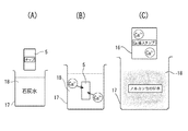
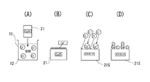
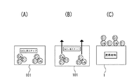
すなわち、前記原料をカルシウムイオンを含む溶液に浸漬させると、溶液が原料に染み込むことでCa導入チップを得ることができる。特に、カルシウムイオンを含む溶液としてアルカリ性の溶液を用いる場合、図12(A)に示すように、原料植物としての木質チップ5を石灰水18に浸漬して石灰水18に接触させると、石灰水18中のCaが木質チップ5に導入され、同図(C)に示すように、Ca導入チップ16が得られる。これは、同図(B)に示すように、アルカリによって木質チップ5中の有機物が溶け出し、Caイオンが木質チップ5の成分と反応するからであると考えられる。なお、原料植物を前処理としての接触処理に用いる石灰水(または石灰乳)の濃度としては、Ca(OH)2 0.1重量%〜50重量%が好ましく、0.2重量%〜10重量%がより好ましい。
That is, when the raw material is immersed in a solution containing calcium ions, a Ca-introduced chip can be obtained by the solution soaking into the raw material. In particular, when an alkaline solution is used as a solution containing calcium ions, as shown in FIG. 12A, when the
続いて、前記Ca導入チップ16を、図13(A)に示すように炭化すると、同図(C)に示すようなCa導入炭化チップ(Ca導入炭)21が得られるが、この炭化時に、Ca導入チップ16(同図(B)参照)中の有機物が熱によって分解するのと同時に、CaイオンがCa導入チップ16の微細孔壁表面に析出する〔図13(C)参照〕と考えられる。この場合、CaイオンがCa導入チップ16の微細孔壁表面に析出してくるので〔図13(B)参照〕、微細で高分散状態となることにより、多くの官能基を微細孔壁の隅々から引き出すものと考えられる。
Subsequently, when the
その後、図14(A)に示すように、Ca導入炭21を酸溶液であるHCl溶液12に浸漬すると、同図(B)および(C)に示すように、Ca導入炭21の表面の官能基に結合したカルシウムイオンおよび前記官能基に塩化物イオン(Cl- )が結合して、同図(D)に示すように、前記官能基に塩化物イオンがカルシウムイオンを介してまたは直接結合している酸処理Ca導入炭21Sが得られると考えられる。そして、このようにして得られる酸処理Ca導入炭21Sは、第1発明の農牧地排水浄化材と比べて、多くの官能基を有するので、その陰イオン吸着特性がより優れたものとなる。なお、Ca導入炭21を酸溶液12に浸漬させて上記酸処理を行う場合、減圧下で行うのが好ましく、1330Pa〜13.3Paの圧力範囲で行うのが好ましい。
Thereafter, as shown in FIG. 14 (A), when the Ca-introduced
以上のことから、第2発明の農牧地排水浄化材は、カルシウム導入処理した原料植物を炭化処理して得られる炭化物に酸溶液を接触させることにより陰イオン吸着特性を持たせた炭素材料からなるか、または前記炭素材料を含むことを特徴としている(請求項2)。ここで、原料植物にカルシウムイオンを含む溶液を接触させることにより前記カルシウム導入処理がなされていることが好ましい(請求項3)。なお、原料植物にカルシウムイオンを含む溶液(例えば石灰水等)を接触させる方法としては、前記溶液の滴下、塗布、吹付け、噴霧などが可能であるが、原料植物を前記溶液に浸漬させることが最も効率的である。
カルシウムを含む溶液としては、石灰水、石灰乳の他、酢酸カルシウム溶液や塩化カルシウム溶液等が挙げられ、カルシウムとして0.03〜30重量%、より好ましくは0.1〜7.0重量%含まれるものが好適である。
From the above, the farmland wastewater purification material of the second invention is a carbon material having anion adsorption characteristics by bringing an acid solution into contact with a carbide obtained by carbonizing a raw material plant subjected to calcium introduction treatment. Or comprising the carbon material (claim 2). Here, it is preferable that the calcium introduction treatment is performed by contacting a raw material plant with a solution containing calcium ions (Claim 3). In addition, as a method of bringing a solution (for example, lime water) containing calcium ions into contact with the raw material plant, the solution can be dropped, applied, sprayed, sprayed, etc., but the raw material plant is immersed in the solution. Is the most efficient.
Examples of the solution containing calcium include calcium acetate solution and calcium chloride solution in addition to lime water and lime milk. The calcium content is 0.03 to 30% by weight, more preferably 0.1 to 7.0% by weight. Are preferred.
なお、第1発明のように、植物原料にCaを導入しない場合は、炭化処理の際の加熱温度による炭化物の官能基の生成量の差は少ない。一方、第2発明のように、植物原料に予めCaを導入してある場合には、炭化処理過程で、温度および時間を適切に制御すれば炭化物の官能基をより多く生成させることができる。 In the case where Ca is not introduced into the plant raw material as in the first invention, there is little difference in the generation amount of the functional group of the carbide depending on the heating temperature during the carbonization treatment. On the other hand, when Ca is previously introduced into the plant raw material as in the second invention, more functional groups of carbides can be generated if the temperature and time are appropriately controlled during the carbonization process.
詳しくは、予めCaを導入した植物原料を炭化するに際して、650〜750℃の炭化処理温度を例えば1時間持続させた後、自然冷却させる場合の方が、約600℃および約800℃の炭化処理温度を1時間持続させた後、自然冷却させる場合に比べて、より多くの官能基が形成できることを本発明者らは確認した。すなわち、Caを導入した場合、電子顕微鏡で観察すると、650〜750℃の炭化処理温度で炭化させた炭化物では、Ca化合物の微粒子が炭化物の微細孔壁面に半ば析出して均一に分散している様子が観察された。一方、約600℃の炭化処理温度では、Ca化合物の微粒子の微細孔壁面への析出が十分行われていない様子が観察された。また、約800℃の炭化処理温度では、Ca化合物の微粒子の微細孔壁面への析出は見られるものの、欠落が多くなっている様子が観察された。このように、Caが炭化物の微細孔壁面から官能基をできるだけ多く引出すために必要な炭化処理温度として約650〜750℃、特に約700℃を挙げることができる。 Specifically, when carbonizing a plant material into which Ca has been introduced in advance, carbonization treatment at about 600 ° C. and about 800 ° C. is performed when the carbonization treatment temperature of 650 to 750 ° C. is maintained for, for example, 1 hour and then naturally cooled. The present inventors have confirmed that more functional groups can be formed as compared with the case where the temperature is maintained for 1 hour and then naturally cooled. That is, when Ca is introduced, when observed with an electron microscope, in the carbide carbonized at a carbonization temperature of 650 to 750 ° C., fine particles of the Ca compound are half-deposited on the fine pore wall surface of the carbide and are uniformly dispersed. The situation was observed. On the other hand, at the carbonization temperature of about 600 ° C., it was observed that the Ca compound fine particles were not sufficiently deposited on the fine pore wall surfaces. Moreover, although the precipitation of Ca compound fine particles on the fine pore wall surface was observed at a carbonization temperature of about 800 ° C., it was observed that the number of missing portions increased. Thus, about 650-750 degreeC, especially about 700 degreeC can be mentioned as a carbonization process temperature required in order for Ca to draw out as many functional groups as possible from the fine pore wall surface of a carbide | carbonized_material.
また、炭化処理後の原料植物の接触処理に用いる酸溶液は、HCl、H2 SO4 といった、農牧地排水浄化材の製造時において排水処理に支障のない酸溶液を用いるのが好ましい。そして、この酸溶液の濃度は、0.01mol/L以上(請求項4)が好ましい。これは、酸溶液濃度が0.01mol/Lを下回ると、十分な吸着特性が得られないからである。なお、より詳しくは、前記酸溶液濃度は0.01mol/L〜20mol/Lであり、好ましくは0.1mol/L〜10mol/Lである。また、酸溶液としては、吸着対象陰イオンとイオン交換可能な陰イオンを含むものが望ましいが、炭化前に植物からなる材料を接触させる溶液中に、吸着対象陰イオンとイオン交換が可能な陰イオンを含む場合はこの限りではない。 The acid solution used for the contact treatment of the raw material plant after the carbonization treatment is preferably an acid solution such as HCl or H 2 SO 4 that does not interfere with the waste water treatment during the production of the farmland waste water purification material. The concentration of the acid solution is preferably 0.01 mol / L or more (Claim 4). This is because sufficient adsorption characteristics cannot be obtained when the acid solution concentration is less than 0.01 mol / L. In more detail, the acid solution concentration is 0.01 mol / L to 20 mol / L, preferably 0.1 mol / L to 10 mol / L. The acid solution preferably contains an anion that can exchange ions with the anion to be adsorbed, but the anion that can exchange ions with the anion to be adsorbed in the solution in contact with the plant material before carbonization. This is not the case when ions are included.
また、本発明者らは、鋭意研究の結果、植物からなる原料を炭化する前に、当該原料に予め金属塩化物を含む溶液、例えばCaCl2 を含む溶液を接触させて原料内にCaCl2 を導入しておき、その後、このCaCl2 を導入した原料を炭化すれば、これにより得られる炭化材料が優れた陰イオンの吸着性能を有することを知見するに至った。 Further, the present invention intensively studied, before carbonizing a raw material consisting of plants, a solution containing a pre-metal chlorides in the raw materials, for example the CaCl 2 in the raw material by contacting a solution containing CaCl 2 If the raw material into which the CaCl 2 was introduced was carbonized after introduction, the carbonized material obtained thereby was found to have excellent anion adsorption performance.
したがって、第3発明の農牧地排水浄化材は、金属塩化物を導入処理した原料植物を炭化処理することによりその炭化物に陰イオン吸着特性を持たせた炭素材料からなるか、または前記炭素材料を含むことを特徴としている(請求項5)。炭化物内に含有する金属塩化物の塩化物イオンが陰イオン交換能を発現するため、炭化物は農牧地排水浄化材として機能するのである。なお、原料植物への金属塩化物の導入処理は、金属塩化物を含む溶液を前記原料植物に接触させることによって行え、この接触方法としては、前記溶液の滴下、塗布、吹付け、噴霧等が可能であるが、前記原料植物を前記溶液に浸漬させることが最も効率的である。 Therefore, the farmland wastewater purification material of the third invention is made of a carbon material obtained by carbonizing a raw material plant into which metal chloride has been introduced to give the carbide anion adsorption characteristics, or the carbon material. (Claim 5). Since the chloride ion of the metal chloride contained in the carbide expresses the anion exchange ability, the carbide functions as a farmland wastewater purification material. In addition, the introduction treatment of the metal chloride to the raw material plant can be performed by bringing the solution containing the metal chloride into contact with the raw material plant. Examples of the contact method include dropping, coating, spraying, spraying, and the like of the solution. Although it is possible, it is most efficient to immerse the raw plant in the solution.
上記第3発明の農牧地排水浄化材において、原料植物を、金属塩化物としてCaCl2 を含む溶液に浸漬して、原料にCaイオンとClイオンとを導入処理し、その後、このCaCl2 導入材を炭化して得られるCaCl2 導入炭には、優れた陰イオン吸着性能が認められる。 In Agricultural land drainage purification material of the third invention, the raw material plant is immersed in a solution containing CaCl 2 as a metal chloride, introducing handle and Ca ions and Cl ions in the raw material, then the CaCl 2 introduced The CaCl 2 -introduced carbon obtained by carbonizing the material shows excellent anion adsorption performance.
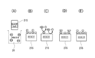
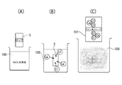
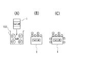
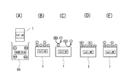
すなわち、例えば、図23(A)に示すように、原料としての木質チップ5をCaCl2 溶液100に浸漬してCaCl2 溶液100に接触させると、CaCl2 溶液100中のCaイオンとClイオンが木質チップ5に導入され、同図(C)に示すように、CaCl2 導入チップ101が得られる。これは、同図(B)に示すように、木質チップ5中の組織、特に通道組織にCaCl2 溶液100が染み込むからである。なお、原料の前処理(接触処理)に用いる前記CaCl2 溶液100の濃度としては、CaCl2 0.1重量%〜50重量%が好ましく、1重量%〜20重量%がコスト的により好ましい。0.1重量%を下回ると高い陰イオン吸着能は発現されず、50重量%を越えても陰イオン吸着能は向上しない。
That is, for example, as shown in FIG. 23 (A), the
続いて、前記CaCl2 導入チップ101を、図24(A)に示すように炭化すると、同図(C)に示すように浄化材1が得られる。この炭化の過程では、CaCl2 導入チップ101中の有機物が熱で分解するのと同時に、ClイオンおよびCaイオンがCaCl2 導入チップ101の微細孔壁表面に析出する。このとき、同図(B)に示すように、ClイオンおよびCaイオンはCaCl2 導入チップ101の微細孔壁表面に微細で高分散状態に析出し、多くの官能基を微細孔壁の隅々から引き出す。その結果、同図(C)に示すように、Clイオンが、微細孔壁表面に引き出された多数の官能基に金属イオン(この場合Caイオン)を介してまたは直接結合された状態になると考えられる。
Subsequently, when the CaCl 2 introduction chip 101 is carbonized as shown in FIG. 24A, the
なお、前記金属塩化物の含有量としては、前記炭化物内に結合される金属塩化物を灰分として2%〜25%含有させてあることが好ましい(請求項6)。炭化物内に結合される金属塩化物とは、炭化物内に単に付着している金属塩化物を除く金属塩化物であり、炭化物内に結合しているため、水や酸で洗い流した後に溶解せずに残留する金属塩化物をいう。2%を下回ると陰イオン吸着能が劣り、25%を上回っても陰イオン吸着能は向上しない傾向がある。 In addition, as content of the said metal chloride, it is preferable to contain 2 to 25% of the metal chloride couple | bonded in the said carbide | carbonized_material as ash (Claim 6). The metal chloride bonded in the carbide is a metal chloride except for the metal chloride that is simply adhered in the carbide. Since it is bonded in the carbide, it does not dissolve after washing with water or acid. The metal chloride remaining in If it is less than 2%, the anion adsorption ability is inferior, and even if it exceeds 25%, the anion adsorption ability tends not to be improved.
さらに、請求項5および6に係る発明において、前記炭化物を水および/または酸に接触させてあることが好ましい(請求項7)。なお、水および/または酸を前記炭化物に接触させる方法としては、水および/または酸の滴下、塗布、吹付け、噴霧などが可能であるが、前記炭化物を水および/または酸に浸漬させることが最も効率的である。
Furthermore, in the invention according to
ここで、前記炭化物に水および/または酸を接触させることが好ましいことの理由は以下のように考えられる。すなわち、図23および図24に示したようにして得られた浄化材(CaCl2 炭)1を、図25(A)に示すように、例えば塩酸102や硫酸等の酸に浸漬(接触)させると、浄化材1に付着していた余分な金属塩化物の結晶が除去される。しかも、酸として塩酸102を用いた場合は、前記浄化材1の官能基と結合するClイオンが新たに増加し、同図(B)から同図(C)に示す状態に変わり、これらのことから、製造した陰イオン吸着能が高まって好ましい。なお、前記炭化物に塩酸102等の酸ではなく水を接触させた場合にも、浄化材1に付着していた余分な金属塩化物の結晶が除去され、陰イオン吸着能を高めることができる。
Here, the reason why it is preferable to contact the carbide with water and / or an acid is considered as follows. That is, the purification material (CaCl 2 charcoal) 1 obtained as shown in FIGS. 23 and 24 is immersed (contacted) in an acid such as
具体的には、前記金属塩化物としてCaCl2 またはBaCl2 が挙げられる(請求項8)。 Specifically, examples of the metal chloride include CaCl 2 and BaCl 2 .
なお、上記第1発明〜第3発明の農牧地排水浄化材における原料植物としては、植物体であれば何でもよいが、天然繊維や木質材料の1種以上からなり、かつ炭化物が微細孔を有するものが好ましく、例えば、間伐材、伐採木、廃木材等全ての木質材料や麻等の天然繊維を挙げることができる。具体的には、吸水性の高い檜や杉等の針葉樹を例えば50mm以下(好適には10mm以下)のサイズにチップ化した木質チップを用いるのが好ましい。さらに、前記木質チップのほかに、竹、おが屑、籾殻、椰子、ビンロウジュ、ジュート、藁、ミカンやリンゴの皮、ミカンやリンゴの搾りかす等の農産廃棄物を用いてもよい。また、植物体の中で特に通道組織(道管、仮道管または師管)を有する部分が好ましい。
前記原料を接触させる溶液として吸着対象陰イオンとイオン交換可能な陰イオン(例えば塩化物イオン等)をほとんど含まずカルシウムイオンを含む溶液(例えば石灰水や石灰乳等)を用いる場合、前記原料としては、カルシウムを導入した後炭化すると、その炭化物の微細孔に100nm以下の粒径のCa化合物が無数に形成されるようなものが好ましい。
また、吸着対象陰イオンとイオン交換可能な陰イオン(例えば塩化物イオン等)とカルシウムイオンを共に含む溶液(例えば塩化カルシウム溶液や酢酸カルシウム溶液等)を用いる場合は、前記原料として、溶液に浸漬する際、溶液が染み込み易いようなものが望ましい。
In addition, as a raw material plant in the farmland wastewater purification material of the said 1st invention-3rd invention, if it is a plant body, it may be anything, but it consists of 1 or more types of natural fiber and a woody material, and a carbide | carbonized_material has a micropore. What has is preferable, for example, all woody materials, such as a thinning material, a felled tree, a waste wood, and natural fibers, such as hemp, can be mentioned. Specifically, it is preferable to use a wood chip in which conifers such as birch and cedar having high water absorption are chipped to a size of, for example, 50 mm or less (preferably 10 mm or less). In addition to the wood chips, agricultural waste such as bamboo, sawdust, rice husk, coconut, areca, jute, cocoon, mandarin orange and apple peel, and mandarin orange and apple pomace may be used. Moreover, the part which has a passage tissue (a road pipe, a temporary path pipe, or a master pipe) in a plant body is especially preferable.
In the case of using a solution (for example, lime water or lime milk) that contains almost no anion (for example, chloride ion) ion-exchangeable with the anion to be adsorbed as the solution in contact with the material (for example, lime water or lime milk), Preferably, when carbon is introduced and then carbonized, countless Ca compounds having a particle size of 100 nm or less are formed in the fine pores of the carbide.
In addition, when using a solution (for example, calcium chloride solution or calcium acetate solution) containing both an anion (for example, chloride ion) ion-exchangeable with the anion to be adsorbed and calcium ion, it is immersed in the solution as the raw material. In this case, it is desirable that the solution easily penetrates.
そして、上記いずれの発明においても、原料植物の炭化処理温度は、400℃〜1000℃であることが好ましい(請求項9)。これは、炭化処理温度が400℃を下回ると、微細孔が発達せず吸着材としての性能が劣り、前記温度が1000℃を超えると、炭素化が進みすぎることにより吸着特性が得られないからである。なお、炭化処理温度としてより好ましくは500℃〜900℃であり、最も好ましいのは約650℃〜750℃である。 And in any said invention, it is preferable that the carbonization temperature of a raw material plant is 400 to 1000 degreeC (Claim 9). This is because if the carbonization temperature is lower than 400 ° C., the fine pores are not developed and the performance as an adsorbent is inferior, and if the temperature exceeds 1000 ° C., the carbonization proceeds excessively, so that the adsorption characteristics cannot be obtained. It is. The carbonization temperature is more preferably 500 ° C to 900 ° C, and most preferably about 650 ° C to 750 ° C.
また、吸着対象の陰イオンを吸着した農牧地排水浄化材から、吸着した陰イオンを除去するとともに、次の吸着対象の陰イオンとイオン交換が可能な陰イオンを前記除去した陰イオンに替えて結合させる(請求項10)ことで、農牧地排水浄化材を繰り返し再生使用することができる。なお、この発明の農牧地排水浄化材で吸着可能な陰イオンは、炭化物の微細孔壁表面の官能基に直接またはカルシウムイオンを介して予め結合させてある陰イオンとイオン交換が可能な陰イオンであり、当然、前記炭化物の微細孔壁表面の官能基に直接またはカルシウムイオンを介して予め結合させてある陰イオン以外の陰イオンである。 In addition, the adsorbed anions are removed from the farmland wastewater purification material that has adsorbed the anions to be adsorbed, and the anions that can exchange ions with the next anion to be adsorbed are replaced with the removed anions. (Claim 10), the farmland wastewater purification material can be repeatedly recycled and used. It should be noted that the anion that can be adsorbed by the farmland wastewater purification material of the present invention can be ion-exchanged with an anion previously bonded to the functional group on the surface of the fine pore wall of the carbide directly or via calcium ion. Naturally, it is an anion other than the anion previously bonded to the functional group on the surface of the microporous wall of the carbide directly or via calcium ion.
そして、第4発明の農牧地排水浄化方法は、請求項1〜10のいずれかに記載の浄化材を用いて農牧地排水を浄化することを特徴とする(請求項11)。前記浄化材は、そのままの形状で使用することもできるが、粒体状または粉体状に加工することができる。したがって、例えば、粒体状の浄化材を、適宜のメッシュを有する網籠やメッシュ状袋体に収納して農牧地排水浄化体とし、この農牧地排水浄化体を農牧地排水と十二分に接触しうる状態に設置することにより、前記農牧地排水中に含まれる陰イオンが確実に吸着される。また、粉体状にした場合は、これを不織布に付着させるなどして農牧地排水浄化体としてもよい。 And the farmland drainage purification method of 4th invention is characterized by purifying farmland drainage using the purification material in any one of Claims 1-10 (invention 11). The purification material can be used as it is, but can be processed into a granular form or a powder form. Therefore, for example, the granular purification material is stored in a net fence or mesh bag having an appropriate mesh to form a farmland drainage purification body, and this farmland drainage purification body is combined with farmland drainage. By installing in a state where it can be contacted in half, the anion contained in the farmland wastewater is reliably adsorbed. Moreover, when it is made into powder form, it is good also as a farmland drainage purification body by making this adhere to a nonwoven fabric.
また、第5発明の農牧地排水浄化方法は、請求項1〜10のいずれかに記載の浄化材を土壌に混合して農牧地排水を浄化することを特徴とする(請求項12)。この方法は、例えば、粒体状または粉体状に加工した前記浄化材を土壌に混合することで実施される。 Moreover, the farmland drainage purification method of 5th invention mixes the purification | cleaning material in any one of Claims 1-10 with soil, It purifies farmland drainage (Claim 12), It is characterized by the above-mentioned. . This method is carried out, for example, by mixing the purification material processed into a granular form or a powder form into soil.
さらに、第6発明の農牧地排水浄化方法は、請求項1〜10のいずれかに記載の浄化材を土壌の下層に埋設して農牧地排水を浄化することを特徴とする(請求項13)。この方法は、例えば、土壌の下層に、粒体状または粉体状に加工した浄化材の層を形成したり、粒体状または粉体状の浄化材を、適宜のメッシュを有する網籠やメッシュ状袋体に収納して農牧地排水浄化体としたものを埋設することにより実施される。また、農牧地排水浄化材には、単なる木炭等、従来から使用されている浄化材を併用してもよい。 Furthermore, the farmland wastewater purification method of 6th invention is characterized by embedding the purification material in any one of Claims 1-10 in the lower layer of soil, and purifying farmland wastewater (Claim). 13). In this method, for example, a layer of a purification material processed into a granular or powdery form is formed in the lower layer of soil, or a granular or powdery purification material is used as a screen mesh having an appropriate mesh. It is carried out by burying what is stored in a mesh-like bag body and made into a farmland drainage purifier. Moreover, you may use together the purification material conventionally used, such as a mere charcoal, for a farmland wastewater purification material.
請求項1に係る発明では、優れた陰イオンの吸着性能を有し、安価に製造することができる農牧地排水浄化材が得られる。しかも、得られる農牧地排水浄化材は、その製造に用いる酸溶液を中和すれば、その製造時の排水処理などになんらの環境問題を生ずることはなく、極めて環境に優しい。
In the invention which concerns on
また、請求項2に係る発明では、陰イオン吸着性能をさらに向上させることのできる農牧地排水浄化材が得られ、その陰イオン吸着特性は、陰イオン交換樹脂と同等あるいは陰イオン交換樹脂よりも優れたものとなる。
Moreover, in the invention which concerns on
請求項3〜10に係る発明でも、所望の陰イオン吸着性能を有し、植物からなる原料を主体として構成することができるので環境にやさしいものとなっているとともに、安価に製造することができる農牧地排水浄化材が得られる。
The inventions according to
さらに、請求項11に係る農牧地排水浄化方法では、例えば、前記農牧地排水浄化材を粒体状に加工してこれを多数適宜の網籠などの容器に収容したり、あるいは、農牧地排水浄化材を粉体状に加工してこれを不織布に付着させるなどして、農牧地排水浄化体とし、この農牧地排水浄化体を農牧地排水と十二分に接触するように設置することにより、農牧地排水中の陰イオンが確実に吸着される。
Further, in the farmland drainage purification method according to
さらに、請求項12および13に係る農牧地排水浄化方法では、浄化材に農牧地排水としての土壌浸透水を効率よくかつ確実に接触させることができ、しかも、浄化材の主成分を炭素材料とすれば、これを超緩効性の窒素肥料及び土壌改良材として、農地における作物の栽培や牧地における牧草の栽培などに有効に利用することができる。
Furthermore, in the farmland drainage purification method according to
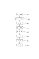
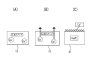
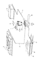
図1〜図4は、この発明の第1実施例を示す。まず、図1(A)は、この発明の農牧地排水浄化材(以下、単に浄化材という)1の一例を示すもので、この実施例では、長さが10mm程度のチップ状に形成されている。そして、図1(B)は、チップ状の浄化材1を適宜径の粒体(ペレット)1aに形成した例を示し、図2は、前記チップ状の浄化材1を適宜径の粒体(ペレット)1aに形成したものを、例えば、外観視直方体形状の網籠2に収容して農牧地排水浄化体3とした例を示している。ここで、網籠2は、容易に化学物質に侵されたり、容易に溶出しないプラスチックやステンレス鋼など化学的に安定な素材よりなり、粒体状の浄化材1aが網目から外部に簡単に抜け出たりしない程度の細かい目合いを有している。なお、図中、4は補強用線材である。また、詳細には、図示していないが、網籠2には開閉・ロック自在の扉を備えた開口が形成されており、浄化材1aを交換または補充することができるように構成されている。
1 to 4 show a first embodiment of the present invention. First, FIG. 1 (A) shows an example of a farmland drainage purification material (hereinafter simply referred to as a purification material) 1 of the present invention. In this embodiment, it is formed in a chip shape having a length of about 10 mm. ing. FIG. 1B shows an example in which the chip-shaped
前記浄化材1を製造する装置および方法について、図3および図4を参照しながら説明する。図3は、浄化材1を製造する装置の一例を概略的に示すもので、この図において、5は原料植物で、この実施例では木質チップである。この木質チップ5は、例えば、吸水性の高い檜や杉等の針葉樹を50mm以下(好適には10mm以下)の適宜のサイズにチップ化したものである。6は木質チップ5を炭化処理する炭化処理炉で、その内部には適宜の熱源7によって加熱される炭化炉本体8が収容されている。この炭化炉本体8の導入部8aから供給された木質チップ5は、適宜の温度(後述する)、適宜の時間(後述する)加熱することにより炭化され、炭化チップ(炭化物)9として排出部8bから排出される。
An apparatus and a method for manufacturing the
そして、図3において、10は前記炭化チップ9を酸処理する装置で、例えば、処理槽11内に適宜濃度のHClが酸溶液12として収容されている。なお、13は処理槽11内に設けられる攪拌用羽根13で、モータ(図示していない)によって回転駆動され、処理槽11内の酸溶液12の濃度を均一になるように攪拌するものである。
In FIG. 3,
また、図3において、14は前記酸処理、中和処理、中和後水洗い処理(以下、酸処理等という)後の炭化チップ(酸処理炭化チップ)9Sを乾燥させる乾燥機で、この乾燥機14には炭化処理炉6から排出される排熱が供給されるようにしてある。
In FIG. 3, 14 is a dryer for drying the carbonized chips (acid-processed carbonized chips) 9S after the acid treatment, neutralization treatment, and post-neutralization water washing treatment (hereinafter referred to as acid treatment). 14 is supplied with exhaust heat discharged from the
上記装置を用いて、原料植物5から浄化材1を得る手順の一例を、図4をも参照しながら説明すると、まず、檜や杉等の針葉樹を10mm以下の適宜のサイズにチップ化した木質チップ5を用意する(ステップS11)。
An example of a procedure for obtaining the
前記木質チップ5は、炭化処理炉6の炭化炉本体8に供給され、400℃〜1000℃の温度範囲で1時間程度加熱され炭化処理される(ステップS12)。これによって、炭化チップ9が得られる。
The
前記炭化チップ9は、酸処理装置10に供給され、処理槽11内の0.01mol/L〜20mol/Lに調整された酸溶液12に浸漬され、酸処理される(ステップS13)。この酸処理後の酸処理炭化チップ9Sは、一般的には乾燥機14において乾燥処理される(ステップS14)。この場合、酸処理炭化チップ9Sをそのまま乾燥機14に送るようにしてもよいが、適宜のアルカリ溶液に浸漬するなどして中和処理したり、さらには、中和処理後に水洗いしてもよい。なお、酸処理炭化チップ9Sを湿潤状態で使用するときは、乾燥処理をしないこともある。
The
そして、前記乾燥処理後の酸処理炭化チップ9Sは、加工を施さずにそのままの形状で使用することもできるが、適宜の加工機を用いて適宜径の粒体(ペレット)1aやより細かな粉体1bに形成される(ステップS15)。そして、例えば、金網よりなる網籠2内に前記ペレット状の浄化材1aを多数収容することにより、図2に示すような農牧地排水浄化体3が得られる(ステップS16)。
The acid-treated
上述の第1実施例では、原料植物(例えば、木質チップ)5を炭化処理し、この炭化処理によって得られる炭化物(例えば、炭化チップ)9を酸溶液12に浸漬処理して前記炭化物9に陰イオン吸着特性を持たせるようにしていたが、原料植物5として、カルシウム導入処理したものを用いるようにしてもよい。以下、これを第2実施例として、図5および図6を参照しながら説明する。
In the first embodiment described above, the raw material plant (for example, wood chips) 5 is carbonized, and the carbide (for example, carbonized chips) 9 obtained by this carbonization treatment is immersed in the
まず、図5は、浄化材1を製造する装置の他の例を概略的に示すもので、この図において、図3に示した符号と同一符号は同一物である。この実施例における装置が図3に示した第1実施例の装置と大きく異なる点を説明すると、15は木質チップ5にCaを導入処理し、Ca導入チップ16とするための装置で、例えば、処理槽17内にカルシウムイオンを含む溶液18を収容してなるものであり、この実施例では、前記カルシウムイオンを含む溶液18は適宜濃度の石灰水(または石灰乳)18である。なお、19は処理槽17内に設けられる攪拌用羽根で、モータ(図示していない)によって回転駆動され、処理槽17内のカルシウムイオンを含む溶液18を濃度が均一になるように攪拌するものである。
First, FIG. 5 schematically shows another example of an apparatus for producing the
また、図5において、20は前記Ca導入処理装置15において得られるCa導入チップ16を乾燥させる乾燥機で、この乾燥機20には炭化処理炉6から排出される排熱が供給されるようにしてある。
In FIG. 5,
上記装置を用いて、原料植物5から浄化材1を得る手順の一例を、図6をも参照しながら説明すると、まず、檜や杉等の針葉樹を10mm以下の適宜のサイズにチップ化した木質チップ5を用意する(ステップS21)。
An example of a procedure for obtaining the
前記木質チップ5をCa導入処理装置15の処理槽17内の5重量%に調整されたカルシウムイオンを含む溶液18内に例えば、3時間以上浸漬する。この場合、溶液18を木質チップ5へ充分染み込ませるため、或いはカルシウムイオンを木質チップ5の成分と充分反応させるために、木質チップ5の浸漬中に、攪拌羽根19を回転させることが好ましい。これによって、Caイオンが木質チップ5の成分と充分反応することができ、木質チップ5にCaが導入されたCa導入チップ16が得られる(ステップS22)。なお、前記Ca導入処理は、石灰乳を用いた方が処理効率がよい。また、溶液18としては、石灰水や石灰乳に代えて、塩化カルシウム溶液や酢酸カルシウム溶液を用いることもできる。
The
前記Ca導入処理酸処理後のCa導入チップ16は、乾燥機20に送られて乾燥処理される(ステップS23)。
The Ca-introduced
前記乾燥処理後のCa導入チップ16は、炭化処理炉6の炭化炉本体8に供給され、700℃の処理温度で、1時間程度加熱して炭化処理される(ステップS24)。これによって、Ca導入炭化チップ(Ca導入炭)21が得られる。
The dried Ca-introduced
前記Ca導入チップ21は、酸処理装置10に供給され、処理槽11内の例えば5mol/Lに調整された酸溶液12に浸漬され、酸処理される(ステップS25)。この場合、攪拌羽根13を回転させるのが好ましく、これによって、Ca導入チップ21の微細孔表面のCaCO3 が酸によって溶解するのを促進させるとともに、塩化物イオンおよびカルシウムイオンをCa導入チップ21の微細孔表面の官能基と充分反応させることができ、所望のCa導入酸処理炭化チップ21Sが得られる。
The
前記酸処理後のCa導入酸処理炭化チップ21Sは、一般的には乾燥機14において乾燥処理される(ステップS26)。この場合、Ca導入酸処理炭化チップ21Sをそのまま乾燥機14に送るようにしてもよいが、適宜のアルカリ溶液に浸漬するなどして中和処理したり、さらには、中和処理後に水洗いしてもよいことはいうまでもない。
The Ca-introduced acid-treated
そして、前記乾燥処理後のCa導入酸処理炭化チップ21Sは、加工を施さずにそのままの形状で使用することもできるが、適宜の加工機を用いて適宜径の粒体(ペレット)1aやより細かな粉体1bに形成される(ステップS27)。そして、例えば、金網よりなる網籠2内に前記ペレット状の浄化材1aを多数収容することにより、図2に示すような農牧地排水浄化体3が得られる(ステップS28)。
The Ca-introduced acid-treated
上記農牧地排水浄化体3は、図2に例示したものに限られるものではなく、例えば、図7に示すように、例えば、ポリエチレンなどのような耐腐食性素材からなる網袋22内に図1に示したチップ状の浄化材1や図3または図5に示したペレット状の浄化材1aを多数収容してマット状の農牧地排水浄化体23を構成してもよい。この場合、網袋22の開口(図示していない)を開閉自在できるようにして、浄化材1または1aの充填・取り出しを容易に行えるようにしておくことが望ましい。
The farmland
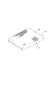
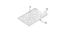
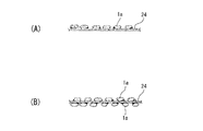
また、図8および図9は、農牧地排水浄化体のさらに他の例を概略的に示すもので、図8に示すものにおいては、透水性のある不織布シート24の一方の面全体に、図9(A)に示すように、ペレット状の浄化材1aを適宜の接着剤を用いて固着してシート状の農牧地排水浄化体25としたものである。また、このシート状の農牧地排水浄化体25において、図9(B)に示すように、不織布シート24の両面に浄化材1aを固着するようにしてもよい。
FIGS. 8 and 9 schematically show still another example of a farmland drainage purifier, and in the case shown in FIG. 8, the entire surface of one side of the
また、図示は省略するが、粉体状の浄化材1bを透水性シートとなる原料に混入するようにして農牧地排水浄化体を構成してもよい。
Moreover, although illustration is abbreviate | omitted, you may comprise a farmland drainage purification body so that the
ここで、前記浄化材1の硝酸性窒素、亜硝酸性窒素およびフッ素の吸着性能について説明する。まず、硝酸性窒素および亜硝酸性窒素の吸着性能の試験方法および試験結果について説明すると、以下の通りである。
Here, the adsorption performance of nitrate nitrogen, nitrite nitrogen and fluorine of the
〔硝酸性窒素および亜硝酸性窒素の吸着性能について〕
〔試験方法〕
硝酸性窒素および亜硝酸性窒素の濃度が50mg/L(50ppm)の硝酸溶液および亜硝酸溶液50mL(標準液)をそれぞれ5つ用意し、
(1)木質チップ5を700℃で炭化させた比較例に用いる木炭9を200mg、
(2)木質チップ5を700℃で炭化させた木炭を1mol/LのFeCl3 溶液に浸漬させた後、水洗いした比較例に用いる塩化鉄木炭200mg、
(3)木質チップ5を700℃で炭化させた木炭を5mol/LのHCl溶液に浸漬させた後、水洗いした酸処理木炭9Sを200mg、
(4)木質チップ5を5重量%の石灰水18に浸漬した後700℃で炭化させた木炭を5mol/LのHCl溶液に浸漬させたCa導入酸処理木炭21Sを200mg、
(5)比較例に用いる陰イオン交換樹脂200mgの5つのサンプルを、それぞれ対応する標準液に入れ、例えば200rpm、20℃の条件下で、10時間振とう後、硝酸溶液および亜硝酸溶液中の硝酸性窒素の濃度および亜硝酸性窒素の濃度をそれぞれ測定し、吸着量を計算した。
[Adsorption performance of nitrate nitrogen and nitrite nitrogen]
〔Test method〕
Prepare 5 nitric acid solutions and 50 mL (standard solution) of nitric acid solution with 50 mg / L (50 ppm) concentration of nitrate nitrogen and nitrite nitrogen,
(1) 200 mg of
(2) 200 mg of iron chloride charcoal used for the comparative example washed with water after the charcoal obtained by carbonizing the
(3) After immersing the charcoal obtained by carbonizing the
(4) 200 mg of Ca-introduced acid-treated
(5) Five samples of 200 mg of an anion exchange resin used in the comparative example were put in the corresponding standard solutions, respectively, shaken for 10 hours under the conditions of, for example, 200 rpm and 20 ° C., and then in a nitric acid solution and a nitrous acid solution. The concentration of nitrate nitrogen and the concentration of nitrite nitrogen were measured, and the amount of adsorption was calculated.
〔結果〕
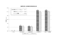
図10は、上記各サンプルの硝酸性窒素および亜硝酸性窒素吸着能の比較を表す。
(1)の700℃炭化の木炭9は、硝酸性窒素および亜硝酸性窒素をほとんど吸着しないのに対して、(2)の塩化鉄木炭は、硝酸性窒素および亜硝酸性窒素をそれぞれ2.75mg/gおよび2.35mg/g吸着した。また、(3)の酸処理木炭9Sは、硝酸性窒素および亜硝酸性窒素をそれぞれ2.50mg/gおよび2.20mg/g吸着した。(5)の陰イオン交換樹脂は、硝酸性窒素および亜硝酸性窒素をそれぞれ10.80mg/gおよび10.00mg/g吸着した。一方、木質チップ5を石灰水18に浸漬した後炭化し、続いて、HCl溶液に浸漬させてなる(4)のCa導入酸処理木炭21Sは、硝酸性窒素および亜硝酸性窒素をそれぞれ10.75mg/gおよび9.80mg/g吸着し、(5)の陰イオン交換樹脂と同等以上の吸着能力を示した。
〔result〕
FIG. 10 shows a comparison of the nitrate nitrogen and nitrite nitrogen adsorption capacities of the above samples.
The
そして、前記Ca導入酸処理木炭21Sが例えば硝酸イオンを吸着するメカニズムは、以下のように考えられる。図15(A)に示すように、Ca導入酸処理木炭21Sを硝酸溶液26に漬けると、Ca導入酸処理木炭21Sの表面の官能基にカルシウムイオンを介してまたは直接前記官能基に結合した塩化物イオン(同図(B)参照)と硝酸溶液26中の硝酸イオンが交換され(同図(C)参照)、硝酸イオンがCa導入酸処理木炭21Sに吸着される(同図(D)参照)。そして、同図(E)は、同図(D)に示すCa導入酸処理木炭21SをKCl(またはNaCl)溶液に漬けたときの変化を示す。すなわち、吸着された硝酸イオンはKCl(またはNaCl)溶液で再度、塩化物イオンと硝酸イオンを交換させて再生可能となる。以下、この再生について説明する。
The mechanism by which the Ca-introduced acid-treated
《再生試験》
〔試験方法〕
前記硝酸性窒素吸着試験を行った後の酸処理木炭9SまたはCa導入酸処理木炭21Sの試料を1mol/LのKCl(またはNaCl)溶液で洗浄し、さらに水洗いした。続いて、標準液を交換して硝酸性窒素濃度が50mg/Lの硝酸溶液50mLを用意し、水洗いした200mgの前記試料の1回目の再生試験を行った。すなわち、前記試料を硝酸溶液に入れ、例えば200rpm、20℃の条件下で、10時間振とう後、前記硝酸溶液中の硝酸性窒素濃度を測定し、吸着量を計算する1回目の再生試験を前記試料を用いて行った。
《Regeneration test》
〔Test method〕
A sample of acid-treated
次に、1回目の再生試験で用いた前記試料を1mol/LのKCl(またはNaCl)溶液で洗浄し、さらに水洗いした。続いて、標準液を交換して硝酸性窒素濃度が50mg/Lの硝酸溶液50mLを用意し、前記水洗いした200mgの前記試料の再生試験を行った。すなわち、前記試料を、硝酸溶液50mLに入れ、例えば200rpm、20℃の条件下で、10時間振とう後、前記硝酸溶液中の硝酸性窒素濃度を測定し、吸着量を計算する2回目の再生試験を前記試料を用いて行った。この処理をあと2回繰り返した。 Next, the sample used in the first regeneration test was washed with a 1 mol / L KCl (or NaCl) solution and further washed with water. Subsequently, the standard solution was replaced to prepare 50 mL of a nitric acid solution having a nitrate nitrogen concentration of 50 mg / L, and a regeneration test of the washed 200 mg of the sample was performed. That is, the sample is put in 50 mL of a nitric acid solution, shaken for 10 hours, for example, under conditions of 200 rpm and 20 ° C., then the concentration of nitrate nitrogen in the nitric acid solution is measured and the amount of adsorption is calculated. The test was performed using the sample. This process was repeated two more times.
〔結果〕
酸処理木炭9Sによる硝酸性窒素の吸着量
初回…2.5mg/g
再生1回目…2.5mg/g
再生2回目…2.4mg/g
再生3回目…2.5mg/g
Ca導入酸処理木炭21Sによる硝酸性窒素の吸着量
初回…10.8mg/g
再生1回目…10.6mg/g
再生2回目…10.9mg/g
再生3回目…10.7mg/g
〔result〕
Amount of nitrate nitrogen adsorbed by acid-treated
The first reproduction ... 2.5mg / g
Second playback: 2.4 mg / g
3rd regeneration ... 2.5mg / g
Adsorption amount of nitrate nitrogen by Ca-introduced acid-treated
The first reproduction ... 10.6mg / g
Second playback: 10.9mg / g
3rd regeneration ... 10.7mg / g
以上のことから、使用した酸処理木炭9SおよびCa導入酸処理木炭21SをそれぞれKCl(またはNaCl)溶液で洗浄し、さらに水洗いすることにより、再生することが分かった。すなわち、硝酸性窒素吸着試験で硝酸性窒素(陰イオン)を吸着した酸処理木炭9SおよびCa導入酸処理木炭21Sをそれぞれ、KCl(またはNaCl)溶液で洗浄し、さらに水洗いすることにより、硝酸性窒素吸着試験で吸着した硝酸性窒素(陰イオン)が除去されて、除去された硝酸性窒素(陰イオン)に替えてCl- を結合させることにより、酸処理木炭9SおよびCa導入酸処理木炭21Sがそれぞれ再生されることが分かった。つまり、一度使用した酸処理木炭9SおよびCa導入酸処理木炭21Sをそれぞれ使用後にその都度洗浄と水洗いを行うことにより、複数回使用できることが確認された。なお、亜硝酸性窒素を吸着した場合でも、陰イオン吸着炭素材料として酸処理木炭9SおよびCa導入酸処理木炭21Sをそれぞれ使用しても、再生する原理は同じである。
From the above, it was found that the acid-treated
〔フッ素吸着性能について〕
〔試験方法〕
フッ化物イオン濃度が50mg/Lの溶液50mL(標準液)を用意し、
(1)木質チップ5を700℃で炭化させた比較例に用いる木炭9Sを100mg、
(2)木質チップ5を700℃で炭化させた木炭を1mol/LのFeCl3 溶液に浸漬させた後、水洗いした比較例に用いる塩化鉄木炭100mg、
(3)木質チップ5を700℃で炭化させた木炭を5mol/LのHCl溶液に浸漬させた後、水洗いした酸処理木炭9Sを100mg、
(4)木質チップ5を5重量%の石灰水に浸漬した後700℃で炭化させた木炭を5mol/LのHCl溶液に浸漬させたCa導入酸処理木炭21Sを100mg、
(5)比較例に用いる陰イオン交換樹脂100mgの5つのサンプルを、それぞれ対応する標準液に入れ、例えば200rpm、20℃の条件下で、10時間振とう後、前記溶液中のフッ化物イオン濃度をそれぞれ測定し、吸着量を計算した。
[Fluorine adsorption performance]
〔Test method〕
Prepare 50 mL (standard solution) of a solution having a fluoride ion concentration of 50 mg / L,
(1) 100 mg of
(2)
(3) After immersing charcoal obtained by carbonizing the
(4) 100 mg of Ca-introduced acid-treated
(5) Five samples of 100 mg of the anion exchange resin used in the comparative example are placed in the corresponding standard solutions, and after shaking for 10 hours under the conditions of, for example, 200 rpm and 20 ° C., the fluoride ion concentration in the solution Was measured, and the amount of adsorption was calculated.
〔結果〕
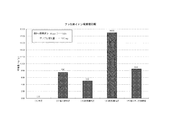
図11は、上記各サンプルのフッ化物イオン吸着能の比較を表す。
(1)の700℃炭化の木炭は、フッ化物イオンをほとんど吸着しないのに対して、(2)の塩化鉄木炭は、7.50mg/gのフッ化物イオンを吸着した。また、(3)の酸処理木炭9Sは、5.00mg/gのフッ化物イオンを吸着した。(5)の陰イオン交換樹脂は、8.50mg/gのフッ化物イオンを吸着した。一方、木質チップ5を石灰水に浸漬した後炭化し、続いて、HCl溶液に浸漬させてなる(4)のCa導入酸処理木炭21Sは、19.00mg/gのフッ化物イオンを吸着し、(5)の陰イオン交換樹脂を大きく超える吸着能力を示した。
〔result〕
FIG. 11 shows a comparison of fluoride ion adsorption capacities of the above samples.
The 700 ° C. charcoal (1) hardly adsorbs fluoride ions, whereas the iron chloride charcoal (2) adsorbs 7.50 mg / g fluoride ions. Moreover, the acid-treated
《再生試験》
〔試験方法〕
次に、前記フッ素吸着試験を行った後の酸処理木炭9SまたはCa導入酸処理木炭21Sの試料を1mol/Lの塩酸(または硫酸)で洗浄し、さらに水洗いした。続いて、標準液を交換してフッ化物イオン濃度が50mg/Lの溶液50mLを用意し、前記水洗いした200mgの前記試料の1回目の再生試験を行った。すなわち、前記試料を前記溶液に入れ、例えば200rpm、20℃の条件下で、10時間振とう後、前記溶液中のフッ化物イオン濃度を測定し、吸着量を計算する1回目の再生試験を前記試料を用いて行った。
《Regeneration test》
〔Test method〕
Next, a sample of acid-treated
次に、1回目の再生試験で用いた前記試料を1mol/Lの塩酸(または硫酸)で洗浄し、さらに水洗いした。続いて、標準液を交換してフッ化物イオン濃度が50mg/Lの前記溶液50mLを用意し、前記水洗いした200mgの前記試料の再生試験を行った。すなわち、前記試料を、前記溶液50mLに入れ、例えば200rpm、20℃の条件下で、10時間振とう後、前記溶液中のフッ化物イオン濃度を測定し、吸着量を計算する2回目の再生試験を前記試料を用いて行った。この処理をあと2回繰り返した。 Next, the sample used in the first regeneration test was washed with 1 mol / L hydrochloric acid (or sulfuric acid) and further washed with water. Subsequently, the standard solution was exchanged to prepare 50 mL of the solution having a fluoride ion concentration of 50 mg / L, and a regeneration test of the washed 200 mg of the sample was performed. That is, the second regeneration test in which the sample is placed in 50 mL of the solution and shaken for 10 hours under the conditions of, for example, 200 rpm and 20 ° C., and then the fluoride ion concentration in the solution is measured and the adsorption amount is calculated. Was performed using the sample. This process was repeated two more times.
〔結果〕
酸処理木炭9Sによるフッ化物イオンの吸着量
初回…2.5mg/g
再生1回目…2.5mg/g
再生2回目…2.4mg/g
再生3回目…2.5mg/g
Ca導入酸処理木炭21Sによるフッ化物イオンの吸着量
初回…18.7mg/g
再生1回目…18.2mg/g
再生2回目…18.9mg/g
再生3回目…18.6mg/g
〔result〕
Adsorption amount of fluoride ion by acid-treated
The first reproduction ... 2.5mg / g
Second playback: 2.4 mg / g
3rd regeneration ... 2.5mg / g
Adsorption amount of fluoride ion by Ca-introduced acid-treated
The first reproduction ... 18.2mg / g
Second playback: 18.9 mg / g
3rd regeneration ... 18.6mg / g
以上のことから、使用した酸処理木炭9SおよびCa導入酸処理木炭21Sをそれぞれ塩酸(または硫酸)で洗浄し、さらに水洗いすることにより、再生することが分かった。すなわち、フッ素吸着試験でフッ化物イオン(陰イオン)を吸着した酸処理木炭9SおよびCa導入酸処理木炭21Sをそれぞれ、塩酸(または硫酸)で洗浄し、さらに水洗いすることにより、フッ素吸着試験で吸着したフッ化物イオン(陰イオン)が除去されて、除去されたフッ化物イオン(陰イオン)に替えてCl- (またはSO4 2- )を結合させることにより、酸処理木炭9SおよびCa導入酸処理木炭21S(陰イオン吸着炭素材料)がそれぞれ再生することが分かった。つまり、一度使用した酸処理木炭9SおよびCa導入酸処理木炭21Sをそれぞれ使用後にその都度洗浄と水洗いを行うことにより、複数回使用できることが確認された。
From the above, it was found that the acid-treated
上述のように、この発明の浄化材1は、硝酸性窒素、亜硝酸性窒素およびフッ素等の陰イオンの吸着性能に優れるが、このような浄化材1を農牧地に適用した例について、以下に説明する。
As mentioned above, although the
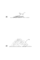
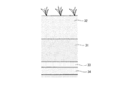
図16は、この発明の第3実施例に係る農牧地排水浄化方法(以下、単に浄化方法という)の一例を示す。この図において、31は農牧地の土壌中に設けられ、土壌改良材等を含む土壌と図1に示した浄化材1とを混合してなる混合層である。この混合層31は、土壌の表面から0〜200cm程度の深さの位置に、0.5〜50cm程度の厚さで設けられ、この実施例では、表層土壌32の下方(下層)に設けられている。ここで、混合層31における土壌と浄化材1との混合比や、混合層31の厚さは、土壌を浸透して下方に進む土壌浸透水中の除去対象とする陰イオン(硝酸性窒素など)の濃度や量などに応じて適宜に設定される。
FIG. 16 shows an example of a farmland drainage purification method (hereinafter simply referred to as purification method) according to the third embodiment of the present invention. In this figure, 31 is a mixed layer which is provided in the soil of farmland and mixes the soil containing a soil improvement material etc. and the
33は、例えば粘土質土壌などからなり、透水性の低い低透水層であり、この低透水層33の直上に前記混合層31が形成されている。
33 is made of, for example, clayey soil or the like and is a low water permeable layer having low water permeability. The
上記の構成からなる浄化方法では、降雨時などに土壌において発生した農牧地排水としての土壌浸透水が、土壌の表層付近から下層に向かい、混合層31を通過する際に、もれなく浄化材1に接触するように構成してあるので、前記土壌浸透水中の硝酸性窒素、亜硝酸性窒素、ヒ素、フッ素等の陰イオンが浄化材1に吸着され、土壌浸透水から除去される。
In the purification method having the above-described configuration, the soil permeated water as farmland drainage generated in the soil during rain or the like moves from the vicinity of the surface layer of the soil toward the lower layer and passes through the
また、前記低透水層33の上に混合層31を設けてあることにより、土壌浸透水が、低透水層33の上方において滞水し、混合層31中の浄化材1に長時間接触するので、上記吸着効果が高まる。しかも、低透水層33の上方に土壌浸透水が滞水することにより、低透水層33の下方の層34が嫌気状態となり、この下方の層34内に存在する脱窒菌が活性化するので、混合層31を通過した土壌浸透水中に硝酸性窒素が含まれていても、この硝酸性窒素は前記脱窒菌の働きによって窒素ガス化することになる。
Further, since the
なお、前記浄化材1は、土壌を耕転するときに定期的に施用するのが効果を持続させる上で好ましい。
In addition, it is preferable to apply the said
また、上記浄化方法において、混合層31に代えて、浄化材1のみからなる浄化層(図示していない)を形成してもよい。さらに、図1に示した浄化材1に代えて、図2に示した浄化材1aを用いてもよい。
In the purification method, a purification layer (not shown) made of only the
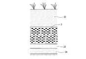
図17は、この発明の第4実施例に係る浄化方法の一例を示す。この図において、図16に示した符号と同一符号は同一物を指す。この図17に示すように、第4実施例に係る浄化方法は、図2に示す農牧地排水浄化体3を土壌中に埋設する。この農牧地排水浄化体3は、土壌の表面から0〜200cm程度の深さの位置に層をなすように任意の数が配置され、この実施例では、表層土壌32の下方(下層)に設けられている。
FIG. 17 shows an example of a purification method according to the fourth embodiment of the present invention. In this figure, the same reference numerals as those shown in FIG. As shown in FIG. 17, the purification method according to the fourth embodiment embeds the farmland
上記の構成からなる浄化方法では、第3実施例に係る浄化方法と同様の効果が得られる。なお、この第4実施例に係る浄化方法において、図2に示す農牧地排水浄化体3に代えて、図8および図9(A)、(B)に示すシート状の農牧地排水浄化体25や、透水性シートとなる原料に粉体状の浄化材1bを混入して形成されたシート状の農牧地排水浄化体を設置してもよい。そして、この場合、例えば、上記2種類のシート状の農牧地排水浄化体が、吸水性あるいは低透水性をもつように構成すれば、シート状の農牧地排水浄化体の中あるいは上方に滞水させることができ、低透水層33が存在することによって得られる効果と同様の効果が得られるので、低透水層33の存在を不要とすることができる。
In the purification method having the above configuration, the same effect as that of the purification method according to the third embodiment can be obtained. In the purification method according to the fourth embodiment, instead of the farmland
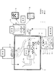
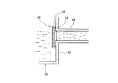
図18は、この発明の第5実施例に係る農牧地排水浄化システム(以下、単に浄化システムという)の一例を示す。この図において、35は農牧地の土壌であり、下層に、水をほとんど通さない不透水層(または低透水層)36が形成されている。そのため、硝酸性窒素等の陰イオンを含む土壌浸透水である農牧地排水が、不透水層36の上方に滞水する。37は上記のように滞水した農牧地排水を適宜の箇所へと流すための例えば側溝からなる流路である。
FIG. 18 shows an example of a farmland drainage purification system (hereinafter simply referred to as a purification system) according to a fifth embodiment of the present invention. In this figure, 35 is soil of farmland, and an impermeable layer (or low water permeable layer) 36 that hardly allows water to pass therethrough is formed in the lower layer. Therefore, farmland drainage, which is soil permeated water containing anions such as nitrate nitrogen, stagnate above the
また、この流路37は、畜産施設Aや堆肥施設Bの周囲にも設けられている。ここで、畜産施設Aの周囲に設けられた流路37には、家畜の排泄物の一部が施設の清掃に用いられた水などとともに流れ込み、また、堆肥施設Bの周囲に設けられた流路37には、堆肥の一部が施設の清掃に用いられた水などとともに流れ込む。従って、畜産施設Aおよび堆肥施設Bの周囲に設けられた流路37に流れ込む水は、アンモニアが一部酸化された硝酸性窒素等の陰イオンを含む農牧地排水である。
The
前記各流路37の下流側には前記農牧地排水を集める手段としての集水枡38が設けられている。この集水枡38は、平面視ほぼ矩形状の底部39と、この底部39の周縁から立ち上がった側壁40とを備えており、前記流路37を流れてきた農牧地排水は、側壁40を通過して集水枡38の内部に至るように構成されている。なお、この実施例では、側壁40を複数(図示例では3つ)の流路37が挿通している。
On the downstream side of each
集水枡38には、適宜のメッシュを有する容器体41が着脱自在に取り付けられる。詳しくは、容器体41は、平面視ほぼ矩形状の底部42と、この底部42の周縁から立ち上がった側壁43と、側壁43の上端から側方に延びるフランジ部44とを備えており、集水枡38内にその上方から挿入すると、フランジ部44が集水枡38の側壁40の上端部に係止され、この状態では、容器体41の側壁43の外面が集水枡38の側壁40の内面にほぼ沿うように構成されている。そして、この容器体41内に、図1に示した浄化材1または図2に示した浄化材1aが収容される。なお、45は集水枡38の開閉自在な蓋である。
A
また、集水枡38の側壁40には、集水枡38の内部に導入された農牧地排水を外部に導出するための排出路46が接続されている。
In addition, a
上記の構成からなる浄化システムでは、流路37に流れ込んだ硝酸性窒素等の陰イオンを含む農牧地排水を、容器体41内の浄化材1(1a)に接触させて効率的に陰イオンを吸着除去することができ、しかも、浄化材1(1a)の交換・回収などを容易に行うことができる。そして、回収した浄化材1(1a)は、上述した方法により再生して再利用することができる。
In the purification system having the above-described configuration, the farmland wastewater containing anions such as nitrate nitrogen that has flowed into the
ここで、上記図18に示した流路37および集水枡38の設置数および設置形態は任意である。
Here, the number of installed
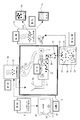
なお、前記浄化材1が収容される容器体41を設ける構成に代えて、例えば、図2に示した農牧地排水浄化体3を集水枡38内に収容してもよく、また、図19に示すように、図8に示したシート状の農牧地排水浄化体24を、適宜のケース47内に積層して農牧地排水浄化体48とし、これを、例えば、集水枡38の側壁40に設けられた排出路46への出口を覆うように設けてもよい。
In addition, instead of the configuration in which the
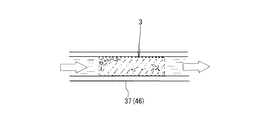
さらに、図20に示すように、流路37内や排出路46内に農牧地排水浄化体3を挿入設置してもよい。この場合、農牧地排水浄化体3が流路37内や排出路46内を容易に移動しないように固定するのが好ましい。
Furthermore, as shown in FIG. 20, the
上述の第2実施例では、原料植物5としてカルシウム導入処理したものを用いているが、原料植物5として、金属塩化物導入処理したものを用いるようにしてもよい。以下、これを第6実施例として、図21および図22を参照しながら説明する。
In the second embodiment described above, the
まず、図21は、浄化材1を製造する装置のさらに他の例を概略的に示すもので、この図において、図5に示した符号と同一符号は同一物である。そして、図21に示すように、前記木質チップ5は、適宜濃度の金属塩化物溶液(この実施の形態ではCaCl2 溶液)91を収容した処理槽92に送られ、この処理槽92内において木質チップ5に対する金属塩化物(この実施の形態ではCaCl2 )の導入処理が行われ、金属塩化物導入チップ93が形成される。なお、94は処理槽92内に設けられる攪拌用羽根で、モータ(図示していない)によって回転駆動され、処理槽92内の液等を攪拌する際に用いられる。なおここで、金属塩化物溶液に対して、Ca(OH)2 を僅かに加えておくことが、陰イオン吸着能を向上させる上で好ましい。
First, FIG. 21 schematically shows still another example of an apparatus for producing the
上記のようにして得られた金属塩化物導入チップ93は、乾燥機20によって乾燥処理された後、炭化処理炉6に送られ、炭化処理される。なお、前記乾燥機20は、炭化処理炉6から排出される排熱を前記乾燥処理に利用するように構成されている。
The metal
そして、金属塩化物導入チップ93は、導入部8aを経て前記炭化炉本体8内に供給され、適宜の温度(後述する)および適宜の時間(後述する)の加熱により炭化され、浄化材1として排出部8bから炭化炉本体8外に排出される。
The metal
その後、前記浄化材1は、水またはHCl溶液(塩酸)96を収容した処理槽97に送られ、この処理槽97内において浄化材1の水またはHCl溶液96に対する接触(浸漬)処理が行われる。なお、98は処理槽97内に設けられる攪拌用羽根で、モータ(図示していない)によって回転駆動され、処理槽97内の液等を攪拌する際に用いられる。酸への接触処理を行った後に水への接触処理を行うこともあり、またその逆の手順で行ってもよい。
Thereafter, the
続いて、前記浄化材1は、乾燥機14に送られ、乾燥処理された後、適宜径の粒体(ペレット)1aやより細かな粉体1bに形成される。なお、前記乾燥機14は、炭化処理炉6から排出される排熱を前記乾燥処理に利用するように構成されている。
Subsequently, the
次に、図21に示した装置を用いて、原料植物5から浄化材1を得る手順の一例を、図21および図22を参照しながら詳細に説明する。まず、檜や杉等の針葉樹を10mm以下の適宜のサイズにチップ化した木質チップ5を用意する(ステップT1)。
Next, an example of a procedure for obtaining the
続いて、前記木質チップ5を処理槽92内の1〜20重量%に調整されたCaCl2 溶液91内に例えば、3時間以上浸漬する。この木質チップ5の浸漬中に、攪拌羽根94を回転させることが好ましい。これによって、CaCl2 溶液91が木質チップ5に染み込むことができ、木質チップ5にCaイオンおよびClイオンが導入された金属塩化物導入チップ93が得られる(ステップT2)。
Subsequently, the
そして、前記金属塩化物導入チップ93は、乾燥機20に送られて乾燥処理される(ステップT3)。
Then, the metal
その後、前記金属塩化物導入チップ93は、炭化処理炉6の炭化炉本体8に供給され、400℃〜1000℃の温度範囲(この実施の形態では700℃)で1時間程度加熱され炭化処理される(ステップT4)。これによって、浄化材1が得られる。
Thereafter, the metal
前記浄化材1は、処理槽97に供給され、処理槽97内の0.01mol/L〜11mol/L(例えば5mol/L)に調整されたHCl溶液96に浸漬処理される(ステップT5)。この場合、攪拌羽根98を回転させるのが好ましく、これによって、浄化材1内に残留する余分な金属塩化物(CaCl2 )の結晶を除去することができるとともに、塩化物イオンをさらに付加させることができ、所望の浄化材1が得られる。
The said
そして、前記浸漬処理後の浄化材1は、一般的には乾燥機14において乾燥処理される(ステップT6)。この場合、浄化材1をそのまま乾燥機14に送るようにしてもよいが、適宜のアルカリ溶液に浸漬するなどして中和処理したり、さらには、中和処理後に水洗いしてもよい。なお、浄化材1を湿潤状態で使用するときは、乾燥処理をしないこともある。
And the purification | cleaning
そして、前記乾燥処理後の浄化材1は、チップ状のまま使用することもできるが、この実施例では適宜の加工機を用いて適宜径の粒体(ペレット)1aやより細かな粉体1bに形成してある(ステップT7)。
And although the
なお、前記浄化材1は、上記ステップT1からステップT7までが全て同一工場内で行われて製造されるものに限られない。例えば、他の工場等にて上記ステップT1〜T7のうちのあるステップまで製造されている場合、途中のステップから始めて浄化材1を製造すればよい。
In addition, the said
なお、上記第6実施例では、金属塩化物として、最も高性能な陰イオン吸着炭素材料が得られるCaCl2 を挙げているが、BaCl2 やMnCl2 等でもよい。 In the sixth embodiment, as the metal chloride, CaCl 2 from which the highest-performance anion-adsorbing carbon material is obtained is exemplified, but BaCl 2 , MnCl 2 or the like may be used.
また、上記第6実施例では、処理槽97内において浄化材1のHCl溶液96に対する接触処理を行っているが、HCl溶液96に代えて水を用いてもよい。この場合、塩化物イオンの付加は行われず、浄化材1内に残留する余分な金属塩化物の結晶を除去するのみとなる。
Further, in the sixth embodiment, the contact treatment with the
さらに、上記実施の形態では、金属塩化物導入チップ93を炭化処理炉6にて炭化処理して浄化材1を得た後、処理槽97へと送っているが、処理槽97へと送らなくてもよい。この場合、前記浄化材1を乾燥機14に送る必要がないので、浄化材1の製造方法は、上記ステップT5,T6が省かれたものとなる。また、この場合、浄化材1の製造方法としては、ステップT1〜T4で終了してもよいし、その後ステップT7を行ってもよい。
Furthermore, in the above embodiment, the metal
次に、第6実施例の浄化材1の硝酸性窒素および亜硝酸性窒素の吸着性能を調べるために行った試験について説明する。硝酸性窒素および亜硝酸性窒素の吸着性能の試験方法および試験結果について説明すると、以下の通りである。
Next, a test conducted for examining the adsorption performance of nitrate nitrogen and nitrite nitrogen of the
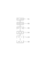
まず、以下に示す計七つのサンプル(1)〜(7)をそれぞれ200mgずつ2組用意した。すなわち、
(1)木質チップ5を700℃で1時間加熱し炭化させて得られた木炭
(2)木質チップ5を700℃で1時間加熱し炭化させ、その後、1mol/LのFeCl3 溶液に浸漬し水洗いして得られた塩化鉄木炭
(3)陰イオン交換樹脂
(4)木質チップ5を10重量%のBaCl2 溶液に浸漬した後700℃で1時間加熱し炭化させて得られたBaCl2 炭
(5)木質チップ5を10重量%のBaCl2 溶液に浸漬した後700℃で1時間加熱し炭化させ、その後、5mol/LのHCl溶液に浸漬処理して得られたHCl処理BaCl2 炭
(6)木質チップ5を10重量%のCaCl2 溶液に浸漬した後700℃で1時間加熱し炭化させて得られたCaCl2 炭
(7)木質チップ5を10重量%のCaCl2 溶液に浸漬した後700℃で1時間加熱し炭化させ、その後、5mol/LのHCl溶液に浸漬処理して得られたHCl処理CaCl2 炭
の計七つのサンプルを2組用意した。なお、(4)〜(7)のサンプルは上記浄化材1に相当するものであり、(1)〜(3)のサンプルは浄化材1と比較するためのものである。
First, two sets of 200 mg each were prepared for a total of seven samples (1) to (7) shown below. That is,
(1) Charcoal obtained by heating and carbonizing the
そして、一方の組の各サンプルを、硝酸性窒素の濃度が50mg/L(50ppm)の硝酸性窒素溶液50mL(第1標準液)に個別に投入し、また、他方の組の各サンプルを、亜硝酸性窒素の濃度が50mg/L(50ppm)の亜硝酸性窒素溶液50mL(第2標準液)に個別に投入した。その後、200rpm、20℃の条件下で、10時間振とう後、第1標準液中の硝酸性窒素の濃度および第2標準液中の亜硝酸性窒素の濃度をそれぞれ測定し、各サンプルによる硝酸性窒素および亜硝酸性窒素の吸着量を計算した。 Then, each sample of one set is individually put into 50 mL (first standard solution) of a nitrate nitrogen solution having a nitrate nitrogen concentration of 50 mg / L (50 ppm), and each sample of the other set is The nitrite nitrogen concentration was individually added to 50 mL (second standard solution) of nitrite nitrogen solution having a concentration of 50 mg / L (50 ppm). Then, after shaking for 10 hours under the conditions of 200 rpm and 20 ° C., the concentration of nitrate nitrogen in the first standard solution and the concentration of nitrite nitrogen in the second standard solution were measured, respectively. The amount of adsorbed nitrogen and nitrite nitrogen was calculated.
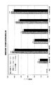
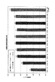
図27は、上記試験によって得られた各サンプルの硝酸性窒素吸着能および亜硝酸性窒素吸着能の比較結果を表す。なお、この図では、各サンプルの硝酸性窒素・亜硝酸性窒素吸着量を一対の棒グラフで示しており、左側の棒グラフが硝酸性窒素吸着量、右側の棒グラフが亜硝酸性窒素吸着量を示している。この図に示す結果から、本発明のサンプルはいずれも高い硝酸性窒素吸着能および亜硝酸性窒素吸着能を持つことがわかる。さらに、(4)のBaCl2 炭と(5)のHCl処理BaCl2 炭の硝酸性窒素および亜硝酸性窒素の吸着量を比較し、また、(6)のCaCl2 炭と(7)のHCl処理CaCl2 炭の硝酸性窒素および亜硝酸性窒素の吸着量を比較することにより、浄化材1の硝酸性窒素・亜硝酸性窒素吸着能をより高めるためには、浄化材1をHCl溶液に浸漬する処理(HCl処理)を行ったほうがよいことがわかる。しかし、HCl処理を行わなくても十分に高い硝酸性窒素・亜硝酸性窒素吸着能を持った浄化材1が得られ、この場合には、HCl溶液の接触処理を行わない分だけ低いコストで浄化材1を製造することができる。
FIG. 27 shows a comparison result of nitrate nitrogen adsorption ability and nitrite nitrogen adsorption ability of each sample obtained by the above test. In this figure, the amount of nitrate nitrogen and nitrite nitrogen adsorption of each sample is shown as a pair of bar graphs. The left bar graph shows the nitrate nitrogen adsorption amount, and the right bar graph shows the nitrite nitrogen adsorption amount. ing. From the results shown in this figure, it can be seen that all the samples of the present invention have high nitrate nitrogen adsorption ability and nitrite nitrogen adsorption ability. Further, the adsorption amounts of nitrate nitrogen and nitrite nitrogen of (4) BaCl 2 charcoal and (5) HCl-treated BaCl 2 charcoal were compared, and (6) CaCl 2 charcoal and (7) HCl adsorbed. In order to further enhance the nitrate nitrogen / nitrite nitrogen adsorption capacity of the
ここで、前記浄化材1が例えば硝酸イオンを吸着するのは、図26(A)に示すように、浄化材(CaCl2 炭)1を硝酸溶液99に浸漬すると、浄化材1の表面の官能基にCaイオンを介してまたは直接結合されたClイオン(同図(B)参照)と硝酸溶液99中のNO3 イオンが交換され(同図(C)参照)、NO3 イオンが浄化材1に吸着される(同図(D)参照)からであると考えられる。
Here, the
また、図26(E)は、NO3 イオンを吸着して同図(D)に示す状態となった浄化材1を、高濃度の塩化物溶液(例えばKClやNaClの金属塩化物溶液、またはHCl溶液)に浸漬した後の状態を示す。すなわち、浄化材1に吸着されたNO3 イオンは、塩化物溶液によってClイオンと交換され、これにより浄化材1が再生され、NO3 イオンなどの陰イオンを吸着可能な状態となる。すなわち、第6実施例の浄化材1は、上記製造方法により常に新たに得られるものに限られず、前記製造方法により得られ、陰イオン(例えばNO3 イオン)を吸着した浄化材1から、吸着した陰イオン(NO3 イオン)が除去されるとともに、次の吸着対象の陰イオン(例えばNO3 イオン)とイオン交換が可能な陰イオン(この実施の形態ではClイオン)を前記除去した陰イオン(NO3 イオン)に替えて結合させることによって得られたもの(すなわち再生されたもの)でもよい。また、上記塩化物溶液に代えて硫酸を用いた場合は、NO3 イオンは、上記Clイオンに代えてSO4 イオンとイオン交換されることとなる。
FIG. 26E shows a
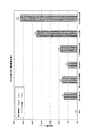
次に、上記ステップT2において木質チップ5を浸漬する金属塩化物溶液(CaCl2 溶液)91の濃度が、製造後の浄化材1の陰イオン吸着能に与える影響を調べるために行った試験について述べる。上記試験は、木質チップ5をCaCl2 溶液91に浸漬した後、700℃で1時間の加熱により炭化し、水洗いして得た浄化材1を、硝酸性窒素の濃度が50mg/L(50ppm)の硝酸性窒素溶液50mL(標準液)に投入し、前記浄化材1の硝酸性窒素の吸着能を調べたもので、前記CaCl2 溶液61として、濃度が1重量%、3重量%、5重量%、7重量%、10重量%、12重量%、14重量%、17重量%、20重量%のものが用いられた。また、比較のために、木質チップ5を10重量%のCaCl2 溶液91に浸漬した後、700℃で1時間の加熱により炭化し、HCl処理して得た浄化材1の硝酸性窒素の吸着能についても調べた。上記試験の結果を図28に示す。
Next, the concentration of metal chloride solution (CaCl 2 solution) 91 soaking the
図28に示す結果から明らかなように、浄化材1の陰イオン吸着能はCaCl2 溶液の濃度に比例して高くなるわけではなく、コスト面等から考えれば、10重量%程度とすることが最も好ましいといえる。また、この図28に示す結果からも、浄化材1の陰イオン吸着能をより高めるためには、浄化材1をHCl処理したほうがよいことがわかる。
As is clear from the results shown in FIG. 28, the anion adsorption capacity of the
次に、硝酸性窒素の吸着に使用された第6実施例の浄化材1をKCl(またはNaCl)溶液によって再生し、再生された浄化材1の硝酸性窒素吸着能を調べるために行った再生試験について説明する。
Next, the
まず、浄化材1として、木質チップ5を10重量%のCaCl2 溶液に浸漬した後700℃で1時間加熱し炭化させて得られたCaCl2 炭を200mg用意した。そして、このCaCl2 炭を、硝酸性窒素の濃度が50mg/L(50ppm)の硝酸性窒素溶液50mL(標準液)に投入し、200rpm、20℃の条件下で、10時間振とう後、前記標準液中の硝酸性窒素の濃度を測定し、前記CaCl2 炭による硝酸性窒素の吸着量を計算した(初回)。
First, 200 mg of CaCl 2 charcoal obtained by immersing the
続いて、前記CaCl2 炭を1mol/LのKCl(またはNaCl)溶液で洗浄し、さらに水洗いして再生した。その後、新たに用意した標準液(すなわち、硝酸性窒素の濃度が50mg/Lの硝酸性窒素溶液50mL)に再生したCaCl2 炭を投入し、200rpm、20℃の条件下で、10時間振とう後、前記標準液中の硝酸性窒素の濃度を測定し、前記CaCl2 炭による硝酸性窒素の吸着量を計算した。そして、このCaCl2 炭の再生から硝酸性窒素の吸着量の計算までの処理を計3回行った(再生一回目〜三回目)。 Subsequently, the CaCl 2 charcoal was washed with a 1 mol / L KCl (or NaCl) solution and further regenerated by washing with water. Thereafter, the regenerated CaCl 2 charcoal is added to a newly prepared standard solution (that is, a nitrate nitrogen solution 50 mL having a nitrate nitrogen concentration of 50 mg / L) and shaken for 10 hours under the conditions of 200 rpm and 20 ° C. Thereafter, the concentration of nitrate nitrogen in the standard solution was measured, and the amount of nitrate nitrogen adsorbed by the CaCl 2 charcoal was calculated. Then, the process from the reproduction of the CaCl 2 charcoal up to the calculation of the amount of adsorbed nitrate nitrogen was carried out three times (reproducing first time - third time).
上記再生試験の結果、すなわち、CaCl2 炭による硝酸性窒素の吸着量は、
初回 …9.5mg/g
再生一回目…9.0mg/g
再生二回目…9.1mg/g
再生三回目…8.8mg/g
であった。以上のことから、硝酸性窒素の吸着に使用した浄化材1(CaCl2 炭)は、濃いKCl(またはNaCl)溶液で洗浄しさらに水洗いすれば再生することが確認された。これは、硝酸性窒素を吸着したCaCl2 炭をKCl(またはNaCl)溶液で洗浄し、さらに水洗いすることにより、CaCl2 炭から硝酸性窒素が除去され、この除去された硝酸性窒素に代わってCl- が官能基に結合されるためであると考えられる。また、上記再生試験の結果から、浄化材1(CaCl2 炭)は、KCl(またはNaCl)溶液を用いた洗浄と水洗いとを行うことにより再生させれば、硝酸性窒素の吸着に複数回使用することができることも確認された。なお、前記浄化材1(CaCl2 炭)を亜硝酸性窒素の吸着に使用した場合でも、再生する原理は同じである。
As a result of the regeneration test, that is, the adsorption amount of nitrate nitrogen by CaCl 2 charcoal is
First time: 9.5mg / g
The first regeneration ... 9.0mg / g
Second regeneration: 9.1 mg / g
The third regeneration ... 8.8mg / g
Met. From the above, it was confirmed that the purification material 1 (CaCl 2 charcoal) used for the adsorption of nitrate nitrogen was regenerated by washing with a concentrated KCl (or NaCl) solution and further with water. This is because the nitrate nitrogen is removed from the CaCl 2 charcoal by washing the CaCl 2 charcoal adsorbing the nitrate nitrogen with a KCl (or NaCl) solution and then washing with water. This is thought to be because Cl - is bonded to a functional group. Moreover, from the result of the regeneration test, the purification material 1 (CaCl 2 charcoal) can be used multiple times for adsorption of nitrate nitrogen if it is regenerated by washing with KCl (or NaCl) solution and washing with water. It was also confirmed that it could be done. Even when the purification material 1 (CaCl 2 charcoal) is used for adsorption of nitrite nitrogen, the principle of regeneration is the same.
次に、第6実施例の浄化材1として、木質チップ5を10重量%のCaCl2 溶液に浸漬した後700℃で1時間加熱し炭化させ、その後、5mol/LのHCl溶液に浸漬処理して得られたHCl処理CaCl2 炭を用い、このHCl処理CaCl2 炭について上記と同様に再生試験を行った結果を示す。
Next, as the
上記再生試験の結果、すなわち、HCl処理CaCl2 炭による硝酸性窒素の吸着量は、
初回 …11.0mg/g
再生一回目…11.0mg/g
再生二回目…10.8mg/g
再生三回目…10.8mg/g
であった。以上のことから、炭化後にHCl溶液に浸漬処理して得られる浄化材1(HCl処理CaCl2 炭)についても、硝酸性窒素の吸着に使用後、濃いKCl(またはNaCl)溶液で洗浄し、さらに水洗いすることにより、再生することが確認された。また、HCl溶液への浸漬処理によって向上したHCl処理CaCl2 炭の硝酸性窒素吸着能は、KCl(またはNaCl)溶液を用いた洗浄と水洗いとを行ってHCl処理CaCl2 炭を繰り返し再生させても持続すること(向上したままであること)が確認された。
As a result of the regeneration test, that is, the adsorption amount of nitrate nitrogen by the HCl-treated CaCl 2 charcoal,
First time ... 11.0mg / g
The first regeneration ... 11.0mg / g
Second regeneration: 10.8mg / g
The third regeneration ... 10.8mg / g
Met. From the above, purifying material 1 (HCl-treated CaCl 2 charcoal) obtained by immersing in HCl solution after carbonization is also washed with concentrated KCl (or NaCl) solution after use for adsorption of nitrate nitrogen, Regeneration was confirmed by washing with water. Further, the nitrate nitrogen adsorption ability of the HCl-treated CaCl 2 charcoal improved by the immersion treatment in the HCl solution is obtained by repeatedly regenerating the HCl-treated CaCl 2 charcoal by washing with KCl (or NaCl) solution and washing with water. Has also been confirmed to remain (still improved).
次に、第6実施例の浄化材1のフッ化物イオンの吸着性能を調べるために行った試験について説明する。まず、この試験を行うために、上述した硝酸性窒素および亜硝酸性窒素の吸着性能の試験で用いた計七つのサンプル(1)〜(7)をそれぞれ50mgずつ1組用意した。そして、各サンプルを、フッ化物イオン濃度が50mg/L(50ppm)の溶液50mL(標準液)に個別に投入し、200rpm、20℃の条件下で、10時間振とう後、標準液中のフッ化物イオンの濃度をそれぞれ測定し、各サンプルによるフッ化物イオンの吸着量を計算した。
Next, a test conducted for examining the fluoride ion adsorption performance of the
図29は、上記試験によって得られた各サンプルのフッ化物イオン吸着能の比較結果を表す。この図に示す結果から、本発明のサンプルはいずれも高いフッ化物イオン吸着能を持つことがわかる。さらに、(4)のBaCl2 炭と(5)のHCl処理BaCl2 炭のフッ化物イオンの吸着量を比較し、また、(6)のCaCl2 炭と(7)のHCl処理CaCl2 炭のフッ化物イオンの吸着量を比較することにより、浄化材1のフッ化物イオン吸着能をより高めるためには、浄化材1をHCl溶液に浸漬する処理(HCl処理)を行ったほうがよいことがわかる。しかし、HCl処理を行わなくても十分に高いフッ化物イオン吸着能を持った浄化材1が得られ、この場合には、HCl溶液の接触処理を行わない分だけ低いコストで浄化材1を製造することができる。
FIG. 29 represents a comparison result of fluoride ion adsorption ability of each sample obtained by the above test. From the results shown in this figure, it can be seen that all the samples of the present invention have high fluoride ion adsorption ability. Furthermore, the adsorption amounts of fluoride ions of (4) BaCl 2 charcoal and (5) HCl-treated BaCl 2 charcoal were compared, and (6) CaCl 2 charcoal and (7) HCl-treated CaCl 2 charcoal were compared. By comparing the adsorption amount of fluoride ions, it is understood that it is better to perform a treatment (HCl treatment) in which the
次に、フッ化物イオンの吸着に使用された上記浄化材1を塩酸(または硫酸)によって再生し、再生された浄化材1のフッ化物イオン吸着能を調べるために行った再生試験について説明する。
Next, a regeneration test performed to regenerate the
まず、浄化材1として、木質チップ5を10重量%のCaCl2 溶液に浸漬した後700℃で1時間加熱し炭化させて得られたCaCl2 炭を200mg用意した。そして、このCaCl2 炭を、フッ化物イオンの濃度が50mg/L(50ppm)の溶液50mL(標準液)に投入し、200rpm、20℃の条件下で、10時間振とう後、前記標準液中のフッ化物イオンの濃度を測定し、前記CaCl2 炭によるフッ化物イオンの吸着量を計算した(初回)。
First, 200 mg of CaCl 2 charcoal obtained by immersing the
続いて、前記CaCl2 炭を1mol/Lの塩酸(または硫酸)で洗浄し、さらに水洗いして再生した。その後、新たに用意した標準液(すなわち、フッ化物イオンの濃度が50mg/Lの溶液50mL)に再生したCaCl2 炭を投入し、200rpm、20℃の条件下で、10時間振とう後、前記標準液中のフッ化物イオンの濃度を測定し、前記CaCl2 炭によるフッ化物イオンの吸着量を計算した。そして、このCaCl2 炭の再生からフッ化物イオンの吸着量の計算までの処理を計3回行った(再生一回目〜三回目)。 Subsequently, the CaCl 2 charcoal was washed with 1 mol / L hydrochloric acid (or sulfuric acid) and further regenerated by washing with water. Thereafter, the regenerated CaCl 2 charcoal was added to a newly prepared standard solution (that is, 50 mL of a solution having a fluoride ion concentration of 50 mg / L), shaken at 200 rpm and 20 ° C. for 10 hours, The concentration of fluoride ions in the standard solution was measured, and the adsorption amount of fluoride ions by the CaCl 2 charcoal was calculated. Then, the processing up to the calculation of the adsorption amount of fluoride ions from the reproduction of the CaCl 2 charcoal was carried out three times (reproducing first time - third time).
上記再生試験の結果、すなわち、CaCl2 炭によるフッ化物イオンの吸着量は、
初回 …22.5mg/g
再生一回目…22.4mg/g
再生二回目…21.7mg/g
再生三回目…21.9mg/g
であった。以上のことから、フッ化物イオンの吸着に使用した浄化材1(CaCl2 炭)は、濃い塩酸(または硫酸)で洗浄しさらに水洗いすれば再生することが確認された。これは、フッ化物イオンを吸着したCaCl2 炭を塩酸(または硫酸)で洗浄し、さらに水洗いすることにより、CaCl2 炭からフッ化物イオンが除去され、この除去されたフッ化物イオンに代わってCl- (またはSO4 2- )が官能基に結合されるためであると考えられる。また、上記再生試験の結果から、浄化材1(CaCl2 炭)は、塩酸(または硫酸)を用いた洗浄と水洗いとを行うことにより再生させれば、フッ化物イオンの吸着に複数回使用することができることも確認された。
As a result of the regeneration test, that is, the adsorption amount of fluoride ions by CaCl 2 charcoal,
First time ... 22.5mg / g
The first reproduction… 22.4mg / g
Second regeneration: 21.7 mg / g
The third regeneration ... 21.9mg / g
Met. From the above, it was confirmed that the purification material 1 (CaCl 2 charcoal) used for the adsorption of fluoride ions was regenerated by washing with concentrated hydrochloric acid (or sulfuric acid) and further with water. This is because the fluoride ions are removed from the CaCl 2 charcoal by washing the CaCl 2 charcoal on which the fluoride ions have been adsorbed with hydrochloric acid (or sulfuric acid) and then washing with water, and instead of the removed fluoride ions, Cl - (Or SO 4 2- ) is considered to be bonded to the functional group. Further, from the result of the regeneration test, the purification material 1 (CaCl 2 charcoal) is used for adsorption of fluoride ions multiple times if it is regenerated by washing with hydrochloric acid (or sulfuric acid) and washing with water. It was also confirmed that it was possible.
次に、第6実施例の浄化材1として、木質チップ5を10重量%のCaCl2 溶液に浸漬した後700℃で1時間加熱し炭化させ、その後、5mol/LのHCl溶液に浸漬処理して得られたHCl処理CaCl2 炭を用い、このHCl処理CaCl2 炭について上記と同様に再生試験を行った結果を示す。
Next, as the
上記再生試験の結果、すなわち、HCl処理CaCl2 炭によるフッ化物イオンの吸着量は、
初回 …32.0mg/g
再生一回目…31.5mg/g
再生二回目…31.4mg/g
再生三回目…31.2mg/g
であった。以上のことから、炭化後にHCl溶液に浸漬処理して得られる浄化材1(HCl処理CaCl2 炭)についても、フッ化物イオンの吸着に使用後、塩酸(または硫酸)溶液で洗浄し、さらに水洗いすることにより、再生することが確認された。また、HCl溶液への浸漬処理によって向上したHCl処理CaCl2 炭のフッ化物イオン吸着能は、塩酸(または硫酸)を用いた洗浄と水洗いとを行ってHCl処理CaCl2 炭を繰り返し再生させても持続すること(向上したままであること)が確認された。
As a result of the regeneration test, that is, the adsorption amount of fluoride ions by the HCl-treated CaCl 2 charcoal,
First time… 32.0mg / g
First reproduction: 31.5mg / g
Second regeneration: 31.4mg / g
The third regeneration ... 31.2mg / g
Met. From the above, purifying material 1 (HCl-treated CaCl 2 charcoal) obtained by immersion treatment in HCl solution after carbonization is also used for adsorption of fluoride ions, then washed with hydrochloric acid (or sulfuric acid) solution, and further washed with water. By doing so, it was confirmed that it was reproduced. Further, the fluoride ion adsorption ability of the HCl-treated CaCl 2 charcoal improved by the immersion treatment in the HCl solution can be obtained by repeatedly regenerating the HCl-treated CaCl 2 charcoal by washing with hydrochloric acid (or sulfuric acid) and washing with water. It was confirmed that it persisted (it remained improved).
1 農牧地排水浄化材
5 原料植物
9 炭化物
12 酸溶液
1 Agricultural and Pasture
Claims (13)
Priority Applications (1)
| Application Number | Priority Date | Filing Date | Title |
|---|---|---|---|
| JP2004348126A JP3828134B2 (en) | 2003-12-05 | 2004-12-01 | Agricultural and pasture drainage purification material and agricultural and pasture drainage purification method using the same |
Applications Claiming Priority (3)
| Application Number | Priority Date | Filing Date | Title |
|---|---|---|---|
| JP2003407705 | 2003-12-05 | ||
| JP2004074123 | 2004-03-16 | ||
| JP2004348126A JP3828134B2 (en) | 2003-12-05 | 2004-12-01 | Agricultural and pasture drainage purification material and agricultural and pasture drainage purification method using the same |
Publications (3)
| Publication Number | Publication Date |
|---|---|
| JP2005296931A true JP2005296931A (en) | 2005-10-27 |
| JP2005296931A5 JP2005296931A5 (en) | 2006-02-23 |
| JP3828134B2 JP3828134B2 (en) | 2006-10-04 |
Family
ID=35329119
Family Applications (1)
| Application Number | Title | Priority Date | Filing Date |
|---|---|---|---|
| JP2004348126A Expired - Fee Related JP3828134B2 (en) | 2003-12-05 | 2004-12-01 | Agricultural and pasture drainage purification material and agricultural and pasture drainage purification method using the same |
Country Status (1)
| Country | Link |
|---|---|
| JP (1) | JP3828134B2 (en) |
Cited By (1)
| Publication number | Priority date | Publication date | Assignee | Title |
|---|---|---|---|---|
| RU2725235C1 (en) * | 2019-06-05 | 2020-06-30 | федеральное государственное бюджетное образовательное учреждение высшего образования "Южно-Российский государственный политехнический университет (НПИ) имени М.И. Платова" | Method for preparation of liquid wastes of cattle-breeding complexes for agricultural use |
Families Citing this family (1)
| Publication number | Priority date | Publication date | Assignee | Title |
|---|---|---|---|---|
| CN109092244A (en) * | 2018-08-13 | 2018-12-28 | 武汉森泰环保股份有限公司 | A kind of decarburization dephosphorization adsorbent and preparation method thereof |
-
2004
- 2004-12-01 JP JP2004348126A patent/JP3828134B2/en not_active Expired - Fee Related
Cited By (1)
| Publication number | Priority date | Publication date | Assignee | Title |
|---|---|---|---|---|
| RU2725235C1 (en) * | 2019-06-05 | 2020-06-30 | федеральное государственное бюджетное образовательное учреждение высшего образования "Южно-Российский государственный политехнический университет (НПИ) имени М.И. Платова" | Method for preparation of liquid wastes of cattle-breeding complexes for agricultural use |
Also Published As
| Publication number | Publication date |
|---|---|
| JP3828134B2 (en) | 2006-10-04 |
Similar Documents
| Publication | Publication Date | Title |
|---|---|---|
| WO2005053846A1 (en) | Anion-adsorbing carbon material, and method and apparatus for producing same | |
| JP3828134B2 (en) | Agricultural and pasture drainage purification material and agricultural and pasture drainage purification method using the same | |
| JP2005296931A5 (en) | ||
| JP3828133B2 (en) | Purifier for water purifier, water purification method using the same, and water purifier | |
| JP3828136B2 (en) | A purification material for a farm, a farm purification method and a farm purification device using the same | |
| JP3828130B2 (en) | Purification material for sewage treatment plant, sewage purification method and sewage treatment facility using the same | |
| JP3718517B1 (en) | Anion adsorbing carbon material and method for producing the same | |
| JP3828131B2 (en) | Waste water treatment purification material except for sewage treatment plant, waste water purification method and waste water treatment apparatus using the same | |
| JP3828135B2 (en) | Aquarium water purification material except for aquaculture, and aquarium water purification method and apparatus using the same | |
| JP2007099619A (en) | Soil-improved fertilizer and plant cultivation method using the same | |
| CN1890027B (en) | Carbon material for anion adsorption, and method and apparatus for producing same | |
| JP4001886B2 (en) | Soil-improved fertilizer and plant cultivation method using the same | |
| JP3828132B2 (en) | Water purification material except for water purifier, water purification method and water purification device using the same | |
| JP2005296930A5 (en) | ||
| JP3822888B2 (en) | Anion adsorption carbon material production equipment | |
| JP3790536B2 (en) | Anion adsorbing carbon material and method for producing the same | |
| JP2005296933A5 (en) | ||
| JP2005296926A5 (en) | ||
| JP3790538B2 (en) | Anion adsorbing carbon material and method for producing the same | |
| JP2005306716A5 (en) | ||
| JP3718520B2 (en) | Anion adsorbing carbon material and method for producing the same | |
| JP3822894B2 (en) | Anion adsorption carbon material production equipment | |
| JP2005296932A5 (en) | ||
| JP3790541B2 (en) | Calcium or metal chloride-introduced plants and carbides used in the production of anion-adsorbing carbon materials and methods for producing them | |
| JP2005296929A5 (en) |
Legal Events
| Date | Code | Title | Description |
|---|---|---|---|
| A621 | Written request for application examination |
Free format text: JAPANESE INTERMEDIATE CODE: A621 Effective date: 20051116 |
|
| A521 | Request for written amendment filed |
Free format text: JAPANESE INTERMEDIATE CODE: A523 Effective date: 20060106 |
|
| A871 | Explanation of circumstances concerning accelerated examination |
Free format text: JAPANESE INTERMEDIATE CODE: A871 Effective date: 20060207 |
|
| A975 | Report on accelerated examination |
Free format text: JAPANESE INTERMEDIATE CODE: A971005 Effective date: 20060313 |
|
| A131 | Notification of reasons for refusal |
Free format text: JAPANESE INTERMEDIATE CODE: A131 Effective date: 20060328 |
|
| A521 | Request for written amendment filed |
Free format text: JAPANESE INTERMEDIATE CODE: A523 Effective date: 20060526 |
|
| TRDD | Decision of grant or rejection written | ||
| A01 | Written decision to grant a patent or to grant a registration (utility model) |
Free format text: JAPANESE INTERMEDIATE CODE: A01 Effective date: 20060627 |
|
| A61 | First payment of annual fees (during grant procedure) |
Free format text: JAPANESE INTERMEDIATE CODE: A61 Effective date: 20060705 |
|
| R150 | Certificate of patent or registration of utility model |
Ref document number: 3828134 Country of ref document: JP Free format text: JAPANESE INTERMEDIATE CODE: R150 Free format text: JAPANESE INTERMEDIATE CODE: R150 |
|
| FPAY | Renewal fee payment (event date is renewal date of database) |
Free format text: PAYMENT UNTIL: 20100714 Year of fee payment: 4 |
|
| FPAY | Renewal fee payment (event date is renewal date of database) |
Free format text: PAYMENT UNTIL: 20110714 Year of fee payment: 5 |
|
| FPAY | Renewal fee payment (event date is renewal date of database) |
Free format text: PAYMENT UNTIL: 20110714 Year of fee payment: 5 |
|
| FPAY | Renewal fee payment (event date is renewal date of database) |
Free format text: PAYMENT UNTIL: 20120714 Year of fee payment: 6 |
|
| FPAY | Renewal fee payment (event date is renewal date of database) |
Free format text: PAYMENT UNTIL: 20120714 Year of fee payment: 6 |
|
| FPAY | Renewal fee payment (event date is renewal date of database) |
Free format text: PAYMENT UNTIL: 20130714 Year of fee payment: 7 |
|
| LAPS | Cancellation because of no payment of annual fees |