JP3828135B2 - Aquarium water purification material except for aquaculture, and aquarium water purification method and apparatus using the same - Google Patents
Aquarium water purification material except for aquaculture, and aquarium water purification method and apparatus using the same Download PDFInfo
- Publication number
- JP3828135B2 JP3828135B2 JP2004348584A JP2004348584A JP3828135B2 JP 3828135 B2 JP3828135 B2 JP 3828135B2 JP 2004348584 A JP2004348584 A JP 2004348584A JP 2004348584 A JP2004348584 A JP 2004348584A JP 3828135 B2 JP3828135 B2 JP 3828135B2
- Authority
- JP
- Japan
- Prior art keywords
- aquarium water
- water purification
- anion
- solution
- purification material
- Prior art date
- Legal status (The legal status is an assumption and is not a legal conclusion. Google has not performed a legal analysis and makes no representation as to the accuracy of the status listed.)
- Expired - Fee Related
Links
Images


Description
この発明は、主に水棲生物や両棲生物を飼育するための生物飼育用水槽(例えば、水族館の水槽や業務用あるいは家庭用水槽)の水槽水の浄化に用いられ、硝酸イオン等の陰イオンを吸着する養殖場用を除く水槽水浄化材並びにこれを用いた水槽水浄化方法および装置に関する。 The present invention is mainly used for the purification of aquarium water in aquaculture tanks (eg, aquarium tanks, commercial or household tanks) for raising aquatic organisms and amphibian organisms. The present invention relates to an aquarium water purification material excluding an adsorbing farm, and an aquarium water purification method and apparatus using the same.
魚類は尿中の含窒素性終末産物として、アンモニア、尿素、クレアチンをこの順に多く排泄する。そして、一般に淡水魚は尿量が多いが、含窒素性終末産物が少なく、逆に海産魚は尿量は少ないものの総窒素量が多い傾向にある。尿素はそれ自体は無害であるが、水中で速やかに分解されることにより、強い毒性を有するアンモニアと二酸化炭素になる。また、水中のアンモニア(NH3 )はそのままの形で存在したり、溶解してアンモニウムイオン(NH4 + )になったりするが、その割合は全アンモニア量と水温およびpH値によって定まる。そして、全アンモニアの毒性はその量と水温とpHが高いほど強くなる。 Fish excretes ammonia, urea, and creatine in this order as nitrogen-containing end products in urine. In general, freshwater fish have a large amount of urine, but there are few nitrogenous end products. Conversely, marine fish have a small amount of urine but tend to have a large amount of total nitrogen. Urea is harmless in itself, but is rapidly decomposed in water to become highly toxic ammonia and carbon dioxide. In addition, ammonia (NH 3 ) in water exists as it is or dissolves to form ammonium ions (NH 4 + ), but the ratio is determined by the total ammonia amount, water temperature, and pH value. And the toxicity of total ammonia becomes stronger as the amount, water temperature and pH are higher.
さらに、アンモニアは細菌などの作用によって酸化(硝化)されて亜硝酸になるが、その中毒にかかると、魚類の血液の酸素輸送能力が低下し、アンモニア中毒と同じ症状が現れる。その許容量は亜硝酸性窒素で1〜2ppmとされている。次いで、亜硝酸がさらに酸化すると硝酸となり、この硝酸の許容量はニジマスの場合で370ppm、ウナギやヒラメの場合は300〜400ppmとされている。 Furthermore, ammonia is oxidized (nitrified) by the action of bacteria and the like to become nitrous acid. However, when poisoning occurs, the oxygen transport ability of fish blood decreases, and the same symptoms as ammonia poisoning appear. The allowable amount is 1 to 2 ppm for nitrite nitrogen. Next, when nitrous acid is further oxidized, it becomes nitric acid. The allowable amount of nitric acid is 370 ppm for rainbow trout and 300 to 400 ppm for eel and flounder.
ところが、魚類の飼育水は循環させることが多いので硝酸はたまる一方であり、その濃度が数百〜数千ppmになることがある。また、近年は工場排水や生活排水などにも硝酸性窒素や亜硝酸性窒素が含まれているので、これが海水や上水に含まれる硝酸イオンや亜硝酸イオンの量を引き上げることもあった。 However, since the breeding water of fish is often circulated, nitric acid is still accumulating, and its concentration may be several hundred to several thousand ppm. In recent years, nitrate nitrogen and nitrite nitrogen are also contained in factory wastewater and domestic wastewater, which may increase the amount of nitrate ions and nitrite ions contained in seawater and tap water.
上述したことからも明らかなように、前記生物飼育用水槽内において、魚などアンモニアや尿素を排泄する生物を飼育する場合、水槽水を放置しておくと、硝酸性窒素や亜硝酸性窒素の濃度が生物にとって有害となる程度にまで高まるので、従来より、水槽水の浄化
処理が行われている。
As is clear from the above, when raising an organism that excretes ammonia or urea, such as fish, in the biological aquarium, if the aquarium water is left untreated, nitrate nitrogen and nitrite nitrogen Since the concentration increases to a level that is harmful to living organisms, purification of aquarium water has been conventionally performed.
例えば、水槽水を清浄に保つためのものとして、特許文献1に示す浄化システムがある。この浄化システムは、水槽水中の亜硝酸性窒素を硝酸性窒素に変換するための硝化槽と、バイオエレクトロ脱窒法によって前記水槽水に含まれる硝酸性窒素を除去する脱窒槽とを備えている。そして、前記浄化システムによれば、硝化槽および脱窒槽によって、水棲生物に悪影響を与えずに、水槽水中の亜硝酸性窒素および硝酸性窒素を除去することができる。
しかし、特許文献1に記載された浄化システムでは、専用の硝化槽および脱窒槽を必要とするので高価となり、水槽水中の硝酸性窒素や亜硝酸性窒素を低コストで除去することができないのが現状である。
However, the purification system described in
ところで、木炭は、活性炭とともに代表的な多孔質炭素材料であり、調湿材、河川浄化材、土壌改良材などとして広く用いられ、例えば、排ガス中の塩素系ガスや硫黄酸化物などの除去にも利用されている。これは、活性炭と同様に、多孔質炭素材料の内部の微細孔による吸着特性を利用しているに過ぎず、陰イオンの形態で存在する硝酸性窒素または亜硝酸性窒素などはほとんど吸着しない。 By the way, charcoal is a typical porous carbon material together with activated carbon, and is widely used as a humidity control material, river purification material, soil improvement material, etc. For example, for removing chlorine-based gas and sulfur oxide in exhaust gas. Is also used. Like activated carbon, this utilizes only the adsorption characteristics due to the fine pores inside the porous carbon material and hardly adsorbs nitrate nitrogen or nitrite nitrogen present in the form of anions.
この発明は、上述の事柄に留意してなされたもので、その目的は、安価で環境に優しく陰イオン吸着性に優れた養殖場用を除く水槽水浄化材並びにこれを用いた水槽水浄化方法および装置を提供することである。 The present invention has been made in consideration of the above-mentioned matters, and the object thereof is an aquarium water purification material excluding aquaculture that is inexpensive, environmentally friendly and excellent in anion adsorption, and an aquarium water purification method using the same And providing a device.
本発明者らは、酸溶液を炭化物に接触させて得られた素材について検討した結果、炭化処理温度や前記酸溶液の濃度にも依るが、この素材が優れた陰イオン吸着性能を持つことを知見するに至った。 As a result of examining the material obtained by bringing the acid solution into contact with the carbide, the present inventors have found that this material has excellent anion adsorption performance, depending on the carbonization temperature and the concentration of the acid solution. I came to know.
すなわち、例えば、原料植物を炭化処理して得られる炭化物である木炭に、塩酸(HCl)、硫酸(H2 SO4 )等の酸溶液を接触(酸処理)させれば、この素材に陰イオン吸着能が発現される。これは、原料植物の炭化物の微細孔壁面に存在する官能基に、吸着対象の陰イオンとイオン交換可能である陰イオンが結合したためである。 That is, for example, if charcoal, which is a carbide obtained by carbonizing a raw material plant, is brought into contact (acid treatment) with an acid solution such as hydrochloric acid (HCl) or sulfuric acid (H 2 SO 4 ), an anion is added to the material. Adsorption ability is expressed. This is because an anion capable of ion exchange with an anion to be adsorbed is bonded to a functional group present on the fine pore wall surface of the carbide of the raw material plant.
したがって、第1発明の水槽水浄化材は、養殖場用を除く水槽水浄化材であって、原料植物を炭化処理して得られる炭化物(ただし活性炭を除く)に酸溶液を接触させることにより、吸着対象の陰イオンとイオン交換が可能な陰イオンを結合させて陰イオン吸着特性を持たせた炭素材料からなるか、または前記炭素材料を含むことを特徴としている(請求項1)。なお、酸溶液を炭化物に接触させる方法としては、酸溶液の滴下、塗布、吹付、噴霧などが可能であるが、炭化物を酸溶液に浸漬させることが最も効率的である。また、前記酸溶液としては、例えば、水に溶けたときに水素イオンを生じる物質を含む水溶液であるHCl溶液やH2 SO4 溶液などが挙げられる。 Therefore, the aquarium water purification material of the first invention is an aquarium water purification material excluding those used for aquaculture, and by contacting an acid solution with a carbide obtained by carbonizing a raw material plant (excluding activated carbon) , The anion to be adsorbed is combined with an anion capable of ion exchange to be made of a carbon material having anion adsorption characteristics, or includes the carbon material (claim 1). In addition, as a method of bringing the acid solution into contact with the carbide, the acid solution can be dropped, applied, sprayed, sprayed, etc., but it is most efficient to immerse the carbide in the acid solution. Examples of the acid solution include an HCl solution and an H 2 SO 4 solution that are aqueous solutions containing a substance that generates hydrogen ions when dissolved in water.
また、本発明者らは、前記原料植物を炭化する前に、当該原料植物にカルシウムイオンを含む溶液(陽イオンとして主にカルシウムイオンが含まれるのが望ましい)、例えば水酸化カルシウム(Ca(OH)2 )の飽和水溶液(石灰水)または懸濁液(石灰乳)を含浸させて、原料植物にCaを導入処理しておき、その後、このCa導入材を炭化し、得られたCa導入炭をHCl、H2 SO4 等の酸で処理(酸溶液を接触処理)すると、より優れた陰イオン吸着特性が得られることを見出した。 In addition, the inventors of the present invention prior to carbonizing the raw material plant, a solution containing calcium ions in the raw material plant (desirably containing mainly calcium ions as cations), such as calcium hydroxide (Ca (OH 2 ) A saturated aqueous solution (lime water) or suspension (lime milk) of 2) is impregnated, Ca is introduced into the raw material plant, and then the Ca-introduced material is carbonized. It was found that when an acid was treated with an acid such as HCl or H 2 SO 4 (an acid solution was contact-treated), more excellent anion adsorption characteristics could be obtained.
すなわち、前記原料をカルシウムイオンを含む溶液に浸漬させると、溶液が原料に染み込むことでCa導入チップを得ることができる。特に、カルシウムイオンを含む溶液としてアルカリ性の溶液を用いる場合、図11(A)に示すように、原料植物としての木質チップ5を石灰水18に浸漬して石灰水18に接触させると、石灰水18中のCaが木質チップ5に導入され、同図(C)に示すように、Ca導入チップ16が得られる。これは、同図(B)に示すように、アルカリによって木質チップ5中の有機物が溶け出し、Caイオンが木質チップ5の成分と反応するからであると考えられる。なお、原料植物を前処理としての接触処理に用いる石灰水(または石灰乳)の濃度としては、Ca(OH)2 0.1重量%〜50重量%が好ましく、0.2重量%〜10重量%がより好ましい。
That is, when the raw material is immersed in a solution containing calcium ions, a Ca-introduced chip can be obtained by the solution soaking into the raw material. In particular, when an alkaline solution is used as a solution containing calcium ions, as shown in FIG. 11A, when the
続いて、前記Ca導入チップ16を、図12(A)に示すように炭化すると、同図(C)に示すようなCa導入炭化チップ(Ca導入炭)21が得られるが、この炭化時に、Ca導入チップ16(同図(B)参照)中の有機物が熱によって分解するのと同時に、CaイオンがCa導入チップ16の微細孔壁表面に析出する〔同図(C)参照〕と考えられる。この場合、CaイオンがCa導入チップ16の微細孔壁表面に析出してくるので〔同図(B)参照〕、微細で高分散状態となることにより、多くの官能基を微細孔壁の隅々から引き出すものと考えられる。
Subsequently, when the Ca
その後、図13(A)に示すように、Ca導入炭21を酸溶液であるHCl溶液12に浸漬すると、同図(B)および(C)に示すように、Ca導入炭21の表面の官能基に結合したカルシウムイオンおよび前記官能基に塩化物イオン(Cl- )が結合して、同図(D)に示すように、前記官能基に塩化物イオンがカルシウムイオンを介してまたは直接結合している酸処理Ca導入炭21Sが得られると考えられる。そして、このようにして得られる酸処理Ca導入炭21Sは、第1発明の浄化材と比べて、多くの官能基を有するので、その陰イオン吸着特性がより優れたものとなる。なお、Ca導入炭21を酸溶液12に浸漬させて上記酸処理を行う場合、減圧下で行うのが好ましく、1330Pa〜13.3Paの圧力範囲で行うのが好ましい。
Thereafter, as shown in FIG. 13A, when the Ca-introduced
以上のことから、第2発明の水槽水浄化材は、養殖場用を除く水槽水浄化材であって、カルシウム導入処理した原料植物を炭化処理して得られる炭化物に酸溶液を接触させることにより、吸着対象の陰イオンとイオン交換が可能な陰イオンを結合させて陰イオン吸着特性を持たせた炭素材料からなるか、または前記炭素材料を含むことを特徴としている(請求項2)。ここで、原料植物にカルシウムイオンを含む溶液を接触させることにより前記カルシウム導入処理がなされていることが好ましい(請求項3)。なお、原料植物にカルシウムイオンを含む溶液(例えば石灰水等)を接触させる方法としては、前記溶液の滴下、塗布、吹付け、噴霧などが可能であるが、原料植物を前記溶液に浸漬させることが最も効率的である。 カルシウムを含む溶液としては、石灰水、石灰乳の他、酢酸カルシウム溶液や塩化カルシウム溶液等が挙げられ、カルシウムとして0.03〜30重量%、より好ましくは0.1〜7.0重量%含まれるものが好適である。 From the above, the aquarium water purification material of the second invention is an aquarium water purification material excluding those used for aquaculture, and by bringing an acid solution into contact with a carbide obtained by carbonizing a calcium-treated raw material plant. The anion to be adsorbed is combined with an anion capable of ion exchange and is made of a carbon material having anion adsorption characteristics, or includes the carbon material (claim 2). Here, it is preferable that the calcium introduction treatment is performed by contacting a raw material plant with a solution containing calcium ions (Claim 3). In addition, as a method of bringing a solution (for example, lime water) containing calcium ions into contact with the raw material plant, the solution can be dropped, applied, sprayed, sprayed, etc., but the raw material plant is immersed in the solution. Is the most efficient. Examples of the solution containing calcium include calcium acetate solution and calcium chloride solution in addition to lime water and lime milk. The calcium content is 0.03 to 30% by weight, more preferably 0.1 to 7.0% by weight. Are preferred.
なお、第1発明のように、植物原料にCaを導入しない場合は、炭化処理の際の加熱温度による炭化物の官能基の生成量の差は少ない。一方、第2発明のように、植物原料に予めCaを導入してある場合には、炭化処理過程で、温度および時間を制御すれば炭化物の官能基をより多く生成させることができる。 In the case where Ca is not introduced into the plant raw material as in the first invention, there is little difference in the generation amount of the functional group of the carbide depending on the heating temperature during the carbonization treatment. On the other hand, when Ca is previously introduced into the plant material as in the second invention, more functional groups of carbides can be generated by controlling the temperature and time during the carbonization process.
詳しくは、予めCaを導入した植物原料を炭化するに際して、約650〜750℃の炭
化処理温度を例えば1時間持続させた後、自然冷却させる場合の方が、約600℃および約800℃の炭化処理温度を1時間持続させた後、自然冷却させる場合に比べて、より多くの官能基が形成できることを本発明者らは確認した。すなわち、Caを導入した場合、電子顕微鏡で観察すると、約650〜750℃の炭化処理温度で炭化させた炭化物では、Ca化合物の微粒子が炭化物の微細孔壁面に半ば析出して均一に分散している様子が観察された。一方、約600℃の炭化処理温度では、Ca化合物の微粒子の微細孔壁面への析出が十分行われていない様子が観察された。また、約800℃の炭化処理温度では、Ca化合物の微粒子の微細孔壁面への析出は見られるものの、欠落が多くなっている様子が観察された。このように、Caが炭化物の微細孔壁面から官能基をできるだけ多く引出すために必要な炭化処理温度として約650〜750℃、特に約700℃を挙げることができる。
Specifically, when carbonizing a plant material into which Ca has been introduced in advance, the carbonization temperature of about 650 to 750 ° C., for example, is maintained for about 1 hour, and then naturally cooled is about 600 ° C. and about 800 ° C. The present inventors have confirmed that more functional groups can be formed as compared with the case where the treatment temperature is maintained for 1 hour and then the mixture is naturally cooled. That is, when Ca is introduced, when observed with an electron microscope, when the carbide is carbonized at a carbonization temperature of about 650 to 750 ° C., fine particles of the Ca compound are half-deposited on the fine pore wall surface of the carbide and uniformly dispersed. I was observed. On the other hand, at the carbonization temperature of about 600 ° C., it was observed that the Ca compound fine particles were not sufficiently deposited on the fine pore wall surfaces. Moreover, although the precipitation of Ca compound fine particles on the fine pore wall surface was observed at a carbonization temperature of about 800 ° C., it was observed that the number of missing portions increased. Thus, about 650-750 degreeC, especially about 700 degreeC can be mentioned as a carbonization process temperature required in order for Ca to draw out as many functional groups as possible from the fine pore wall surface of a carbide | carbonized_material.
また、炭化処理後の原料植物の接触処理に用いる酸溶液は、HCl、H2 SO4 といった、水槽水浄化材の製造時において排水処理に支障のない酸溶液を用いるのが好ましい。そして、この酸溶液の濃度は、0.01mol/L以上(請求項4)が好ましい。これは、酸溶液濃度が0.01mol/Lを下回ると、十分な吸着特性が得られないからである。なお、より詳しくは、前記酸溶液濃度は0.01mol/L〜20mol/Lであり、好ましくは0.1mol/L〜10mol/Lである。また、酸溶液としては、吸着対象陰イオンとイオン交換可能な陰イオンを含むものが望ましいが、炭化前に植物からなる材料を接触させる溶液中に、吸着対象陰イオンとイオン交換が可能な陰イオンを含む場合はこの限りではない。 The acid solution used for the contact treatment of the raw material plant after the carbonization treatment is preferably an acid solution such as HCl or H 2 SO 4 that does not interfere with the waste water treatment during the production of the aquarium water purification material. The concentration of the acid solution is preferably 0.01 mol / L or more (Claim 4). This is because sufficient adsorption characteristics cannot be obtained when the acid solution concentration is less than 0.01 mol / L. In more detail, the acid solution concentration is 0.01 mol / L to 20 mol / L, preferably 0.1 mol / L to 10 mol / L. The acid solution preferably contains an anion that can exchange ions with the anion to be adsorbed, but the anion that can exchange ions with the anion to be adsorbed in the solution in contact with the plant material before carbonization. This is not the case when ions are included.
また、本発明者らは、鋭意研究の結果、植物からなる原料を炭化する前に、当該原料に予め金属塩化物を含む溶液、例えばCaCl2 を含む溶液を接触させて原料内にCaCl2 を導入しておき、その後、このCaCl2 を導入した原料を炭化すれば、これにより得られる炭化材料が優れた陰イオンの吸着性能を有することを知見するに至った。 In addition, as a result of intensive research, the inventors of the present invention made a solution containing a metal chloride, for example, a solution containing CaCl 2 in advance, before carbonizing a plant-made raw material so that CaCl 2 is contained in the raw material. If the raw material into which the CaCl 2 was introduced was carbonized after introduction, the carbonized material obtained thereby was found to have excellent anion adsorption performance.
したがって、第3発明の水槽水浄化材は、養殖場用を除く水槽水浄化材であって、金属塩化物を導入処理した原料植物を炭化処理することにより、その炭化物に吸着対象の陰イオンとイオン交換が可能な塩化物イオンを結合させて陰イオン吸着特性を持たせた炭素材料からなるか、または前記炭素材料を含むことを特徴としている(請求項5)。炭化物内に含有する金属塩化物の塩化物イオンが陰イオン交換能を発現するため、炭化物は水槽水浄化材として機能するのである。なお、原料植物への金属塩化物の導入処理は、金属塩化物を含む溶液を前記原料植物に接触させることによって行え、この接触方法としては、前記溶液の滴下、塗布、吹付け、噴霧等が可能であるが、前記原料植物を前記溶液に浸漬させることが最も効率的である。 Accordingly, the aquarium water purification material of the third invention is an aquarium water purification material excluding those used for aquaculture, and by carbonizing the raw material plant into which the metal chloride has been introduced, the anion to be adsorbed on the carbide is obtained. It consists of the carbon material which combined the chloride ion which can be ion-exchanged, and gave the anion adsorption characteristic, or is characterized by including the said carbon material (Claim 5). Since the chloride ion of the metal chloride contained in the carbide expresses the anion exchange ability, the carbide functions as an aquarium water purification material. In addition, the introduction treatment of the metal chloride to the raw material plant can be performed by bringing the solution containing the metal chloride into contact with the raw material plant. Examples of the contact method include dropping, coating, spraying, spraying, and the like of the solution. Although it is possible, it is most efficient to immerse the raw plant in the solution.
上記第3発明の水槽水浄化材において、原料植物を、金属塩化物としてCaCl2 を含む溶液に浸漬して、原料にCaイオンとClイオンとを導入処理し、その後、このCaCl2 導入材を炭化して得られるCaCl2 導入炭には、優れた陰イオン吸着性能が認められる。 In the aquarium water purification material of the third invention, the raw material plant is immersed in a solution containing CaCl 2 as a metal chloride to introduce Ca ions and Cl ions into the raw material, and then the CaCl 2 introduction material is used. The CaCl 2 -introduced carbon obtained by carbonization has excellent anion adsorption performance.
すなわち、例えば、図23(A)に示すように、原料としての木質チップ5をCaCl2 溶液100に浸漬してCaCl2 溶液100に接触させると、CaCl2 溶液100中のCaイオンとClイオンが木質チップ5に導入され、同図(C)に示すように、CaCl2 導入チップ101が得られる。これは、同図(B)に示すように、木質チップ5中の組織、特に通道組織にCaCl2 溶液100が染み込むからである。なお、原料の前処理(接触処理)に用いる前記CaCl2 溶液100の濃度としては、CaCl2 0.1重量%〜50重量%が好ましく、1重量%〜20重量%がコスト的により好ましい。0.1重量%を下回ると高い陰イオン吸着能は発現されず、50重量%を越えても陰イオン吸着能は向上しない。
That is, for example, as shown in FIG. 23 (A), the
続いて、前記CaCl2 導入チップ101を、図24(A)に示すように炭化すると、同図(C)に示すように浄化材1が得られる。この炭化の過程では、CaCl2 導入チップ101中の有機物が熱で分解するのと同時に、ClイオンおよびCaイオンがCaCl2 導入チップ101の微細孔壁表面に析出する。このとき、同図(B)に示すように、ClイオンおよびCaイオンはCaCl2 導入チップ101の微細孔壁表面に微細で高分散状態に析出し、多くの官能基を微細孔壁の隅々から引き出す。その結果、同図(C)に示すように、Clイオンが、微細孔壁表面に引き出された多数の官能基に金属イオン(この場合Caイオン)を介してまたは直接結合された状態になると考えられる。
Subsequently, when the CaCl 2 introduction chip 101 is carbonized as shown in FIG. 24A, the
なお、前記金属塩化物の含有量としては、前記炭化物内に結合される金属塩化物を灰分として2%〜25%含有させてあることが好ましい(請求項6)。炭化物内に結合される金属塩化物とは、炭化物内に単に付着している金属塩化物を除く金属塩化物であり、炭化物内に結合しているため、水や酸で洗い流した後に溶解せずに残留する金属塩化物をいう。2%を下回ると陰イオン吸着能が劣り、25%を上回っても陰イオン吸着能は向上しない傾向がある。 In addition, as content of the said metal chloride, it is preferable to contain 2 to 25% of the metal chloride couple | bonded in the said carbide | carbonized_material as ash (Claim 6). The metal chloride bonded in the carbide is a metal chloride except for the metal chloride that is simply adhered in the carbide. Since it is bonded in the carbide, it does not dissolve after washing with water or acid. The metal chloride remaining in If it is less than 2%, the anion adsorption ability is inferior, and even if it exceeds 25%, the anion adsorption ability tends not to be improved.
さらに、請求項5および6に係る発明において、前記炭化物を水および/または酸に接触させてあることが好ましい(請求項7)。なお、水および/または酸を前記炭化物に接触させる方法としては、水および/または酸の滴下、塗布、吹付け、噴霧などが可能であるが、前記炭化物を水および/または酸に浸漬させることが最も効率的である。
Furthermore, in the invention according to
ここで、前記炭化物に水および/または酸を接触させることが好ましいことの理由は以下のように考えられる。すなわち、図23および図24に示したようにして得られた浄化材(CaCl2 炭)1を、図25(A)に示すように、例えば塩酸102や硫酸等の酸に浸漬(接触)させると、浄化材1に付着していた余分な金属塩化物の結晶が除去される。しかも、酸として塩酸102を用いた場合は、前記浄化材1の官能基と結合するClイオンが新たに増加し、同図(B)から同図(C)に示す状態に変わり、これらのことから、製造した陰イオン吸着能が高まって好ましい。なお、前記炭化物に塩酸102等の酸ではなく水を接触させた場合にも、浄化材1に付着していた余分な金属塩化物の結晶が除去され、陰イオン吸着能を高めることができる。
Here, the reason why it is preferable to contact the carbide with water and / or an acid is considered as follows. That is, the purification material (CaCl 2 charcoal) 1 obtained as shown in FIGS. 23 and 24 is immersed (contacted) in an acid such as
具体的には、前記金属塩化物としてCaCl2 またはBaCl2 が挙げられる(請求項8)。 Specifically, examples of the metal chloride include CaCl 2 and BaCl 2 .
なお、上記第1発明〜第3発明の水槽水浄化材における原料植物としては、植物体であれば何でもよいが、天然繊維や木質材料の1種以上からなり、かつ炭化物が微細孔を有するものが好ましく、例えば、間伐材、伐採木、廃木材等全ての木質材料や麻等の天然繊維を挙げることができる。具体的には、吸水性の高い檜や杉等の針葉樹を例えば50mm以下(好適には10mm以下)のサイズにチップ化した木質チップを用いるのが好ましい。さらに、前記木質チップのほかに、竹、おが屑、籾殻、椰子、ビンロウジュ、ジュート、藁、ミカンやリンゴの皮、ミカンやリンゴの搾りかす等の農産廃棄物を用いてもよい。また、植物体の中で特に通道組織(道管、仮道管または師管)を有する部分が好ましい。
前記原料を接触させる溶液として吸着対象陰イオンとイオン交換可能な陰イオン(例えば塩化物イオン等)をほとんど含まずカルシウムイオンを含む溶液(例えば石灰水や石灰乳等)を用いる場合、前記原料としては、カルシウムを導入した後炭化すると、その炭化物の微細孔に100nm以下の粒径のCa化合物が無数に形成されるようなものが好ましい。
また、吸着対象陰イオンとイオン交換可能な陰イオン(例えば塩化物イオン等)とカル
シウムイオンを共に含む溶液(例えば塩化カルシウム溶液や酢酸カルシウム溶液等)を用いる場合は、前記原料として、溶液に浸漬する際、溶液が染み込み易いようなものが望ましい。
In addition, as a raw material plant in the tank water purification material of the said 1st invention-3rd invention, if it is a plant body, anything may be sufficient, but it consists of 1 or more types of a natural fiber and a woody material, and a carbide | carbonized_material has a micropore. Preferably, examples include all woody materials such as thinned wood, felled trees, waste wood, and natural fibers such as hemp. Specifically, it is preferable to use a wood chip in which conifers such as birch and cedar having high water absorption are chipped to a size of, for example, 50 mm or less (preferably 10 mm or less). In addition to the wood chips, agricultural waste such as bamboo, sawdust, rice husk, eggplant, areca, jute, cocoon, mandarin orange and apple peel, and mandarin orange and apple pomace may be used. Moreover, the part which has a passage tissue (a road pipe, a temporary path pipe, or a master pipe) in a plant body is especially preferable.
In the case of using a solution (for example, lime water or lime milk) that contains almost no anion (for example, chloride ion) ion-exchangeable with the anion to be adsorbed as the solution in contact with the material (for example, lime water or lime milk), Preferably, when carbon is introduced and then carbonized, countless Ca compounds having a particle size of 100 nm or less are formed in the fine pores of the carbide.
In addition, when using a solution (for example, calcium chloride solution or calcium acetate solution) containing both an anion (for example, chloride ion) ion-exchangeable with the anion to be adsorbed and calcium ion, it is immersed in the solution as the raw material. In this case, it is desirable that the solution easily penetrates.
そして、上記いずれの発明においても、原料植物の炭化処理温度は、400℃〜1000℃であることが好ましい(請求項9)。これは、炭化処理温度が400℃を下回ると、微細孔が発達せず吸着材としての性能が劣り、前記温度が1000℃を超えると、炭素化が進みすぎることにより吸着特性が得られないからである。なお、炭化処理温度としてより好ましくは500℃〜900℃であり、最も好ましいのは約650℃〜750℃である。 And in any said invention, it is preferable that the carbonization temperature of a raw material plant is 400 to 1000 degreeC (Claim 9). This is because if the carbonization temperature is lower than 400 ° C., the fine pores are not developed and the performance as an adsorbent is inferior. It is. The carbonization temperature is more preferably 500 ° C to 900 ° C, and most preferably about 650 ° C to 750 ° C.
また、吸着対象の陰イオンを吸着した水槽水浄化材から、吸着した陰イオンを除去するとともに、次の吸着対象の陰イオンとイオン交換が可能な陰イオンを前記除去した陰イオンに替えて結合させる(請求項10)ことで、水槽水浄化材を繰り返し再生使用することができる。なお、この発明の水槽水浄化材で吸着可能な陰イオンは、炭化物の微細孔壁表面の官能基に直接またはカルシウムイオンを介して予め結合させてある陰イオンとイオン交換が可能な陰イオンであり、当然、前記炭化物の微細孔壁表面の官能基に直接またはカルシウムイオンを介して予め結合させてある陰イオン以外の陰イオンである。 In addition, it removes the adsorbed anion from the water purification material that has adsorbed the anion to be adsorbed, and replaces the anion that can exchange ions with the next anion to be adsorbed by the removed anion. By making it (claim 10), the water tank water purification material can be repeatedly recycled. The anion that can be adsorbed by the aquarium water purification material of the present invention is an anion that can be ion-exchanged with an anion previously bonded to a functional group on the surface of the fine pore wall of the carbide directly or via calcium ion. Of course, it is an anion other than the anion previously bonded to the functional group on the surface of the fine pore wall of the carbide directly or via a calcium ion.
そして、第4発明の水槽水浄化方法は、養殖場用を除く水槽水浄化方法であって、請求項1〜10のいずれかに記載の浄化材を用いて水槽水を浄化することを特徴とする(請求項11)。前記浄化材は、そのままの形状で使用することもできるが、粒体状または粉体状に加工することができる。したがって、例えば、粒体状の浄化材を、適宜のメッシュを有する網籠やメッシュ状袋体に収納して水槽水浄化体とし、この水槽水浄化体を水槽水と十二分に接触しうる状態に設置することにより、前記水槽水中に含まれる陰イオンが確実に吸着される。また、粉体状にした場合は、これを不織布に付着させるなどして水槽水浄化体としてもよい。 And the aquarium water purification method of 4th invention is an aquarium water purification method except for aquaculture, Comprising: Aquarium water is purified using the purification material in any one of Claims 1-10, (Claim 11). The purification material can be used as it is, but can be processed into a granular form or a powder form. Therefore, for example, the granular purification material can be stored in a mesh bag or mesh bag having an appropriate mesh to form an aquarium water purification body, and the aquarium water purification body can be sufficiently in contact with the aquarium water. By installing in the state, the anion contained in the aquarium water is reliably adsorbed. Moreover, when powdered, it is good also as a water tank water purification body by making this adhere to a nonwoven fabric.
第5発明は、第4発明のより具体的な構成を示すもので、この発明の水槽水浄化装置は、養殖場用を除く水槽水浄化装置であって、水槽水が循環する循環流路を備え、この循環流路中に請求項1〜10のいずれかに記載の浄化材を設けて水槽水を浄化するように構成してあることを特徴としている(請求項12)。上記水槽水浄化装置によれば、水槽水が浄化材に効率よく接触するので、水槽水中の陰イオンを確実に吸着・除去することができ、水槽水を飼育に良好な状態で長期間維持することができる。また、水槽水浄化材には、セラミック粒等、従来から使用されている浄化材を併用してもよい。
5th invention shows the more concrete structure of 4th invention, The aquarium water purification apparatus of this invention is an aquarium water purification apparatus except for aquaculture, Comprising: The circulation channel through which aquarium water circulates And a purification material according to any one of
請求項1に係る発明では、優れた陰イオンの吸着性能を有し、安価に製造することができる水槽水浄化材が得られる。しかも、得られる水槽水浄化材は、その製造に用いる酸溶液を中和すれば、その製造時の排水処理などになんらの環境問題を生ずることはなく、極めて環境に優しい。
In the invention which concerns on
また、請求項2に係る発明では、上記の効果を奏するだけでなく、原料植物をカルシウム導入処理した後炭化する際に、炭化処理温度を適宜に設定することにより、陰イオン吸着性能をさらに向上させることのできる水槽水浄化材が得られ、その陰イオン吸着特性は、陰イオン交換樹脂と同等あるいは陰イオン交換樹脂よりも優れたものとなる。
Further, in the invention according to
請求項3〜10に係る発明でも、所望の陰イオン吸着性能を有し、また、原料植物を炭化処理して得られる炭化物に陰イオン吸着特性を持たせた炭素材料からなるか、または前記炭素材料を含むので、環境にやさしいものとなっているとともに、安価に製造すること
ができる水槽水浄化材が得られる。
Also in the inventions according to
さらに、請求項11および12に係る水槽水浄化方法および装置では、例えば、前記水槽水浄化材を粒体状に加工してこれを多数適宜の網籠などの容器に収容したり、あるいは、水槽水浄化材を粉体状に加工してこれを不織布に付着させるなどして、水槽水浄化体とし、この水槽水浄化体を水槽水と十二分に接触するように設置することにより、水槽水中の陰イオンが確実に吸着される。
Furthermore, in the aquarium water purification method and apparatus according to
図1〜図4は、この発明の第1実施例を示す。まず、図1(A)は、この発明の養殖場用を除く水槽水浄化材(以下、単に浄化材という)1の一例を示すもので、この実施例では、長さが10mm程度のチップ状に形成されている。そして、図1(B)は、チップ状の浄化材1を適宜径の粒体(ペレット)1aに形成した例を示し、図2は、前記チップ状の浄化材1を適宜径の粒体(ペレット)1aに形成したものを、例えば、外観視直方体形状の網籠2に収容して水槽水浄化体3とした例を示している。ここで、網籠2は、容易に化学物質に侵されたり、容易に溶出しないプラスチックやステンレス鋼など化学的に安定な素材よりなり、粒体状の浄化材1aが網目から外部に簡単に抜け出たりしない程度の細かい目合いを有している。なお、図中、4は補強用線材である。また、詳細には、図示していないが、網籠2には開閉・ロック自在の扉を備えた開口が形成されており、浄化材1aを交換または補充することができるように構成されている。
1 to 4 show a first embodiment of the present invention. First, FIG. 1 (A) shows an example of an aquarium water purification material (hereinafter simply referred to as a purification material) 1 except for aquaculture according to the present invention. In this embodiment, a chip shape having a length of about 10 mm is shown. Is formed. FIG. 1B shows an example in which the chip-shaped
前記浄化材1を製造する装置および方法について、図3および図4を参照しながら説明する。図3は、浄化材1を製造する装置の一例を概略的に示すもので、この図において、5は原料植物で、この実施例では木質チップである。この木質チップ5は、例えば、吸水性の高い檜や杉等の針葉樹を50mm以下(好適には10mm以下)の適宜のサイズにチップ化したものである。6は木質チップ5を炭化処理する炭化処理炉で、その内部には適宜の熱源7によって加熱される炭化炉本体8が収容されている。この炭化炉本体8の導入部8aから供給された木質チップ5は、適宜の温度(後述する)、適宜の時間(後述する)加熱することにより炭化され、炭化チップ(炭化物)9として排出部8bから排出される。
An apparatus and a method for manufacturing the
そして、図3において、10は前記炭化チップ9を酸処理する装置で、例えば、処理槽11内に適宜濃度のHClが酸溶液12として収容されている。なお、13は処理槽11内に設けられる攪拌用羽根13で、モータ(図示していない)によって回転駆動され、処理槽11内の酸溶液12の濃度を均一になるように攪拌するものである。
In FIG. 3,
また、図3において、14は前記酸処理、中和処理、中和後水洗い処理(以下、酸処理等という)後の炭化チップ(酸処理炭化チップ)9Sを乾燥させる乾燥機で、この乾燥機14には炭化処理炉6から排出される排熱が供給されるようにしてある。
In FIG. 3, 14 is a dryer for drying the carbonized chips (acid-processed carbonized chips) 9S after the acid treatment, neutralization treatment, and post-neutralization water washing treatment (hereinafter referred to as acid treatment). 14 is supplied with exhaust heat discharged from the
上記装置を用いて、原料植物5から浄化材1を得る手順の一例を、図4をも参照しながら説明すると、まず、檜や杉等の針葉樹を10mm以下の適宜のサイズにチップ化した木質チップ5を用意する(ステップS11)。
An example of a procedure for obtaining the
前記木質チップ5は、炭化処理炉6の炭化炉本体8に供給され、400℃〜1000℃の温度範囲で1時間程度加熱され炭化処理される(ステップS12)。これによって、炭化チップ9が得られる。
The
前記炭化チップ9は、酸処理装置10に供給され、処理槽11内の0.01mol/L〜20mol/Lに調整された酸溶液12に浸漬され、酸処理される(ステップS13)
。この酸処理後の酸処理炭化チップ9Sは、一般的には乾燥機14において乾燥処理される(ステップS14)。この場合、酸処理炭化チップ9Sをそのまま乾燥機14に送るようにしてもよいが、適宜のアルカリ溶液に浸漬するなどして中和処理したり、さらには、中和処理後に水洗いしてもよい。なお、酸処理炭化チップ9Sを湿潤状態で使用するときは、乾燥処理をしないこともある。
The
. The acid-treated
そして、前記乾燥処理後の酸処理炭化チップ9Sは、加工を施さずにそのままの形状で使用することもできるが、適宜の加工機を用いて適宜径の粒体(ペレット)1aやより細かな粉体1bに形成される(ステップS15)。そして、例えば、金網よりなる網籠2内に前記ペレット状の浄化材1aを多数収容することにより、図2に示すような水槽水浄化体3が得られる(ステップS16)。
The acid-treated
上述の第1実施例では、原料植物(例えば、木質チップ)5を炭化処理し、この炭化処理によって得られる炭化物(例えば、炭化チップ)9に酸溶液12を接触処理して前記炭化物9に陰イオン吸着特性を持たせるようにしていたが、原料植物5として、カルシウム導入処理したものを用いるようにしてもよい。以下、これを第2実施例として、図5および図6を参照しながら説明する。
In the first embodiment described above, the raw material plant (for example, wood chips) 5 is carbonized, and the carbide (for example, carbonized chips) 9 obtained by the carbonization is contact-treated with the
まず、図5は、浄化材1を製造する装置の他の例を概略的に示すもので、この図において、図3に示した符号と同一符号は同一物である。この実施例における装置が図3に示した第1実施例の装置と大きく異なる点を説明すると、15は木質チップ5にCaを導入処理し、Ca導入チップ16とするための装置で、例えば、処理槽17内にカルシウムイオンを含む溶液18を収容してなるものであり、この実施例では、前記カルシウムイオンを含む溶液18は適宜濃度の石灰水(または石灰乳)18である。なお、19は処理槽17内に設けられる攪拌用羽根で、モータ(図示していない)によって回転駆動され、処理槽17内のカルシウムイオンを含む溶液18を濃度が均一になるように攪拌するものである。
First, FIG. 5 schematically shows another example of an apparatus for producing the
また、図5において、20は前記Ca導入処理装置15において得られるCa導入チップ16を乾燥させる乾燥機で、この乾燥機20には炭化処理炉6から排出される排熱が供給されるようにしてある。
In FIG. 5,
上記装置を用いて、原料植物5から浄化材1を得る手順の一例を、図6をも参照しながら説明すると、まず、檜や杉等の針葉樹を10mm以下の適宜のサイズにチップ化した木質チップ5を用意する(ステップS21)。
An example of a procedure for obtaining the
前記木質チップ5をCa導入処理装置15の処理槽17内の5重量%に調整されたカルシウムイオンを含む溶液18内に例えば、3時間以上浸漬する。この場合、溶液18を木質チップ5へ充分染み込ませるため、或いはカルシウムイオンを木質チップ5の成分と充分反応させるために、木質チップ5の浸漬中に、攪拌羽根19を回転させることが好ましい。これによって、Caイオンが木質チップ5の成分と充分反応することができ、木質チップ5にCaが導入されたCa導入チップ16が得られる(ステップS22)。なお、前記Ca導入処理は、石灰乳を用いた方が処理効率がよい。また、溶液18としては、石灰水や石灰乳に代えて、塩化カルシウム溶液や酢酸カルシウム溶液を用いることもできる。
The
前記Ca導入処理酸処理後のCa導入チップ16は、乾燥機20に送られて乾燥処理される(ステップS23)。
The Ca-introduced
前記乾燥処理後のCa導入チップ16は、炭化処理炉6の炭化炉本体8に供給され、7
00℃の処理温度で、1時間程度加熱して炭化処理される(ステップS24)。これによって、Ca導入炭化チップ(Ca導入炭)21が得られる。
The
Carbonization is performed by heating for about 1 hour at a processing temperature of 00 ° C. (step S24). Thereby, a Ca-introduced carbonized chip (Ca-introduced charcoal) 21 is obtained.
前記Ca導入チップ21は、酸処理装置10に供給され、処理槽11内の例えば5mol/Lに調整された酸溶液12に浸漬され、酸処理される(ステップS25)。この場合、攪拌羽根13を回転させるのが好ましく、これによって、Ca導入チップ21の微細孔表面のCaCO3 が酸によって溶解するのを促進させるとともに、塩化物イオンおよびカルシウムイオンをCa導入チップ21の微細孔表面の官能基と充分反応させることができ、所望のCa導入酸処理炭化チップ21Sが得られる。
The
前記酸処理後のCa導入酸処理炭化チップ21Sは、一般的には乾燥機14において乾燥処理される(ステップS26)。この場合、Ca導入酸処理炭化チップ21Sをそのまま乾燥機14に送るようにしてもよいが、適宜のアルカリ溶液に浸漬するなどして中和処理したり、さらには、中和処理後に水洗いしてもよいことはいうまでもない。
The Ca-introduced acid-treated
そして、前記乾燥処理後のCa導入酸処理炭化チップ21Sは、加工を施さずにそのままの形状で使用することもできるが、適宜の加工機を用いて適宜径の粒体(ペレット)1aやより細かな粉体1bに形成される(ステップS27)。そして、例えば、金網よりなる網籠2内に前記ペレット状の浄化材1aを多数収容することにより、図2に示すような水槽水浄化体3が得られる(ステップS28)。
The Ca-introduced acid-treated
上記水槽水浄化体3は、図2に例示したものに限られるものではなく、例えば、図7に示すように、例えば、ポリエチレンなどのような耐腐食性素材からなる網袋22内に図1に示したチップ状の浄化材1や図3または図5に示したペレット状の浄化材1aを多数収容してマット状の水槽水浄化体23を構成してもよい。この場合、網袋22の開口(図示していない)を開閉自在できるようにして、浄化材1または1aの充填・取り出しを容易に行えるようにしておくことが望ましい。
The aquarium
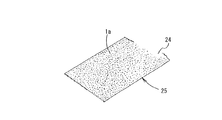
また、図8および図9は、水槽水浄化体のさらに他の例を概略的に示すもので、図8に示すものにおいては、透水性のある不織布シート24の一方の面全体に、図9(A)に示すように、ペレット状の浄化材1aを適宜の接着剤を用いて固着してシート状の水槽水浄化体25としたものである。また、このシート状の水槽水浄化体25において、図9(B)に示すように、不織布シート24の両面に浄化材1aを固着するようにしてもよい。
8 and 9 schematically show still another example of the aquarium water purification body. In the structure shown in FIG. 8, the entire surface of one side of the permeable
また、図示は省略するが、粉体状の浄化材1bを透水性シートとなる原料に混入するようにして水槽水浄化体を構成してもよい。
Although not shown, the aquarium water purification body may be configured such that the
ここで、前記浄化材1の硝酸性窒素、亜硝酸性窒素の吸着性能について説明する。まず、硝酸性窒素および亜硝酸性窒素の吸着性能の試験方法および試験結果について説明すると、以下の通りである。
Here, the adsorption performance of nitrate nitrogen and nitrite nitrogen of the
〔硝酸性窒素および亜硝酸性窒素の吸着性能について〕
〔試験方法〕
硝酸性窒素および亜硝酸性窒素の濃度が50mg/L(50ppm)の硝酸溶液および亜硝酸溶液50mL(標準液)をそれぞれ5つ用意し、
(1)木質チップ5を700℃で炭化させた比較例に用いる木炭9を200mg、
(2)木質チップ5を700℃で炭化させた木炭を1mol/LのFeCl3 溶液に浸漬させた後、水洗いした比較例に用いる塩化鉄木炭200mg、
(3)木質チップ5を700℃で炭化させた木炭を5mol/LのHCl溶液に浸漬させた後、水洗いした酸処理木炭9Sを200mg、
(4)木質チップ5を5重量%の石灰水18に浸漬した後700℃で炭化させた木炭を5mol/LのHCl溶液に浸漬させたCa導入酸処理木炭21Sを200mg、
(5)比較例に用いる陰イオン交換樹脂200mgの5つのサンプルを、それぞれ対応する標準液に入れ、例えば200rpm、20℃の条件下で、10時間振とう後、硝酸溶液および亜硝酸溶液中の硝酸性窒素の濃度および亜硝酸性窒素の濃度をそれぞれ測定し、吸着量を計算した。
[Adsorption performance of nitrate nitrogen and nitrite nitrogen]
〔Test method〕
Prepare 5 nitric acid solutions and 50 mL (standard solution) of nitric acid solution with 50 mg / L (50 ppm) concentration of nitrate nitrogen and nitrite nitrogen,
(1) 200 mg of
(2) Iron chloride charcoal 200 mg used in the comparative example washed with water after immersing the charcoal obtained by carbonizing the
(3) After immersing the charcoal obtained by carbonizing the
(4) 200 mg of Ca-introduced acid-treated
(5) Five samples of 200 mg of an anion exchange resin used in the comparative example were put in the corresponding standard solutions, respectively, shaken for 10 hours under the conditions of, for example, 200 rpm and 20 ° C., and then in a nitric acid solution and a nitrous acid solution. The concentration of nitrate nitrogen and the concentration of nitrite nitrogen were measured, and the amount of adsorption was calculated.
〔結果〕
図10は、上記各サンプルの硝酸性窒素および亜硝酸性窒素吸着能の比較を表す。
(1)の700℃炭化の木炭9は、硝酸性窒素および亜硝酸性窒素をほとんど吸着しないのに対して、(2)の塩化鉄木炭は、硝酸性窒素および亜硝酸性窒素をそれぞれ2.75mg/gおよび2.35mg/g吸着した。また、(3)の酸処理木炭9Sは、硝酸性窒素および亜硝酸性窒素をそれぞれ2.50mg/gおよび2.20mg/g吸着した。(5)の陰イオン交換樹脂は、硝酸性窒素および亜硝酸性窒素をそれぞれ10.80mg/gおよび10.00mg/g吸着した。一方、木質チップ5を石灰水18に浸漬した後炭化し、続いて、HCl溶液に浸漬させてなる(4)のCa導入酸処理木炭21Sは、硝酸性窒素および亜硝酸性窒素をそれぞれ10.75mg/gおよび9.80mg/g吸着し、(5)の陰イオン交換樹脂と同等以上の吸着能力を示した。
〔result〕
FIG. 10 shows a comparison of the nitrate nitrogen and nitrite nitrogen adsorption capacities of the above samples.
The
そして、前記Ca導入酸処理木炭21Sが例えば硝酸イオンを吸着するメカニズムは、以下のように考えられる。図14(A)に示すように、Ca導入酸処理木炭21Sを硝酸溶液26に漬けると、Ca導入酸処理木炭21Sの表面の官能基にカルシウムイオンを介してまたは直接前記官能基に結合した塩化物イオン(同図(B)参照)と硝酸溶液26中の硝酸イオンが交換され(同図(C)参照)、硝酸イオンがCa導入酸処理木炭21Sに吸着される(同図(D)参照)。そして、同図(E)は、同図(D)に示すCa導入酸処理木炭21SをKCl(またはNaCl)溶液に漬けたときの変化を示す。すなわち、吸着された硝酸イオンはKCl(またはNaCl)溶液で再度、塩化物イオンと硝酸イオンを交換させて再生可能となる。以下、この再生について説明する。
The mechanism by which the Ca-introduced acid-treated
《再生試験》
〔試験方法〕
前記硝酸性窒素吸着試験を行った後の酸処理木炭9SまたはCa導入酸処理木炭21Sの試料を1mol/LのKCl(またはNaCl)溶液で洗浄し、さらに水洗いした。続いて、標準液を交換して硝酸性窒素濃度が50mg/Lの硝酸溶液50mLを用意し、水洗いした200mgの前記試料の1回目の再生試験を行った。すなわち、前記試料を硝酸溶液に入れ、例えば200rpm、20℃の条件下で、10時間振とう後、前記硝酸溶液中の硝酸性窒素濃度を測定し、吸着量を計算する1回目の再生試験を前記試料を用いて行った。
《Regeneration test》
〔Test method〕
A sample of acid-treated
次に、1回目の再生試験で用いた前記試料を1mol/LのKCl(またはNaCl)溶液で洗浄し、さらに水洗いした。続いて、標準液を交換して硝酸性窒素濃度が50mg/Lの硝酸溶液50mLを用意し、前記水洗いした200mgの前記試料の再生試験を行った。すなわち、前記試料を、硝酸溶液50mLに入れ、例えば200rpm、20℃の条件下で、10時間振とう後、前記硝酸溶液中の硝酸性窒素濃度を測定し、吸着量を計算する2回目の再生試験を前記試料を用いて行った。この処理をあと2回繰り返した。 Next, the sample used in the first regeneration test was washed with a 1 mol / L KCl (or NaCl) solution and further washed with water. Subsequently, the standard solution was replaced to prepare 50 mL of a nitric acid solution having a nitrate nitrogen concentration of 50 mg / L, and a regeneration test of the washed 200 mg of the sample was performed. That is, the sample is put in 50 mL of a nitric acid solution, shaken for 10 hours, for example, under conditions of 200 rpm and 20 ° C., then the concentration of nitrate nitrogen in the nitric acid solution is measured and the amount of adsorption is calculated. The test was performed using the sample. This process was repeated two more times.
〔結果〕
酸処理木炭9Sによる硝酸性窒素の吸着量
初回…2.5mg/g
再生1回目…2.5mg/g
再生2回目…2.4mg/g
再生3回目…2.5mg/g
Ca導入酸処理木炭21Sによる硝酸性窒素の吸着量
初回…10.8mg/g
再生1回目…10.6mg/g
再生2回目…10.9mg/g
再生3回目…10.7mg/g
〔result〕
Amount of nitrate nitrogen adsorbed by acid-treated
The first reproduction ... 2.5mg / g
Second playback: 2.4 mg / g
3rd regeneration ... 2.5mg / g
Adsorption amount of nitrate nitrogen by Ca-introduced acid-treated
The first reproduction ... 10.6mg / g
Second playback: 10.9mg / g
3rd regeneration ... 10.7mg / g
以上のことから、使用した酸処理木炭9SおよびCa導入酸処理木炭21SをそれぞれKCl(またはNaCl)溶液で洗浄し、さらに水洗いすることにより、再生することが分かった。すなわち、硝酸性窒素吸着試験で硝酸性窒素(陰イオン)を吸着した酸処理木炭9SおよびCa導入酸処理木炭21Sをそれぞれ、KCl(またはNaCl)溶液で洗浄し、さらに水洗いすることにより、硝酸性窒素吸着試験で吸着した硝酸性窒素(陰イオン)が除去されて、除去された硝酸性窒素(陰イオン)に替えてCl- を結合させることにより、酸処理木炭9SおよびCa導入酸処理木炭21Sがそれぞれ再生されることが分かった。つまり、一度使用した酸処理木炭9SおよびCa導入酸処理木炭21Sをそれぞれ使用後にその都度洗浄と水洗いを行うことにより、複数回使用できることが確認された。なお、亜硝酸性窒素を吸着した場合でも、陰イオン吸着炭素材料として酸処理木炭9SおよびCa導入酸処理木炭21Sをそれぞれ使用しても、再生する原理は同じである。
From the above, it was found that the acid-treated
上述のように、この発明の浄化材1は、硝酸性窒素、亜硝酸性窒素等の陰イオンの吸着性能に優れるが、このような浄化材1を例えば鑑賞用水槽など実際の生物飼育用水槽に適用した例について、以下に説明する。
As described above, the
図15は、この発明の第3実施例に係る水槽水浄化装置(以下、単に浄化装置という)30を水槽31に適用した例を示す。この図において、水槽31は適宜の素材を用いて透明に形成された鑑賞用水槽で、内部に水(この実施例では淡水)32および金魚など適宜の水棲生物33を収容することができるように構成されている。
FIG. 15 shows an example in which a water tank water purification apparatus (hereinafter simply referred to as a purification apparatus) 30 according to a third embodiment of the present invention is applied to a
一方、浄化装置30は、水槽31内の水、すなわち水槽水32を循環させるための水路34と、前記水槽水32を浄化するための浄化手段35とを備えている。
On the other hand, the
水路34は、一端部36が水槽31の側壁下部に接続され、また、途中に循環用ポンプ37が設けられている。そして、この水路34の他端側に浄化手段35が設けられている。
One
浄化手段35は、水槽水32を濾過するための例えば市販のフィルタ38と、図2に示すように構成された水槽水浄化体3とを上側からこの順に積層した状態でケース39内に収容してなり、このケース39の底部には水槽31へのパイプ40が設けられている。
The purifying means 35 accommodates, for example, a commercially
上記の構成からなる浄化装置30が設置された水槽31では、水槽31内の水槽水32が、水槽31の下部から水路34内に送られた後、ケース39内にその上方から導入され、フィルタ38および水槽水浄化体3を経て浄化された水槽水32がパイプ40を経て再び水槽31内に戻ってくる。ここで、水槽水32が浄化手段35を通過する際に、もれなく網籠2内の浄化材1aに接触するように構成してあるので、水槽水32中の硝酸性窒素、亜硝酸性窒素等の陰イオンが浄化材1aに吸着される。
In the
前記水槽水浄化体3は、種々の形態で設置することができる。例えば、図16に示すように、フックなどの係止部材41を用いて、水槽水浄化体3を水槽31の側壁上端から吊り下げ、網籠2内の浄化材1aの全部が水槽31内の水槽水32中に浸漬する状態となる
ように配置してもよい。
The aquarium
また、図17に示すように、水槽水浄化体3に、適宜のフロート42を付設し、網籠2内の浄化材1aの全部が水槽水32の水面よりも下位に位置しこれと接するようにしてもよい。このように構成した場合、図17中において矢印Aで示す水流によって、網籠2内の浄化材1aが水槽水32内を泳動し、水槽水32と浄化材1aとが十二分に接触することにより、水槽水32中の硝酸性窒素、亜硝酸性窒素等の陰イオンが浄化材1aに吸着される。また、このことは図16に示すように構成した場合についても同様である。
Further, as shown in FIG. 17, an
さらに、図18に示すように、水槽31内に支持部材43を立設し、この支持部材43に水槽水浄化体3を水平に固定してもよい。
Further, as shown in FIG. 18, a
また、図19に示すように、流路34内に水槽水浄化体3を挿入設置してもよい。この場合、水槽水浄化体3が流路34内を容易に移動しないように固定するのが好ましい。
Further, as shown in FIG. 19, the aquarium
上記図16〜図19に示した水槽水浄化体3の設置個数は任意である。
The number of aquarium
そして、図20に示すように、図8に示したシート状の水槽水浄化体24を、適宜のケース44内に積層して水槽水浄化体45とし、これを、例えば、水槽31の側壁に設けられた水路34への出口を覆うように設けてもよい。
And as shown in FIG. 20, the sheet-like water tank
なお、図15〜図20に示す実施例において、水槽30内において飼育する対象としては、魚介類などの水棲生物に限られず、亀などの両棲類であってもよい。また、海水魚など海水中に生息する生物を飼育対象としてもよく、この場合、水槽水32としては海水を用いればよい。そして、水槽水32が海水である場合、その塩化物イオン濃度の影響により、浄化材1aの陰イオン吸着性能が若干低下することになるが、通常の海水における塩化物イオン濃度であれば、浄化材1aは充分に陰イオン吸着効果を発揮することを本発明者らは確認している。
In addition, in the Example shown in FIGS. 15-20, as a target raised in the
また、図15〜図20に示す実施例では、流路34を設けて水槽水32を循環させるようにしているが、このような構成に限られず、例えば、水槽水32を循環させることなく、水槽31内に水槽水浄化体3を設けるだけでもよく、この場合でも、水槽水浄化体3によって水槽水32を浄化することができる。
Moreover, in the Example shown in FIGS. 15-20, although the
上述の第2実施例では、原料植物5としてカルシウム導入処理したものを用いているが、原料植物5として、金属塩化物導入処理したものを用いるようにしてもよい。以下、これを第4実施例として、図21および図22を参照しながら説明する。
In the second embodiment described above, the
まず、図21は、浄化材1を製造する装置のさらに他の例を概略的に示すもので、この図において、図5に示した符号と同一符号は同一物である。そして、図21に示すように、前記木質チップ5は、適宜濃度の金属塩化物溶液(この実施の形態ではCaCl2 溶液)91を収容した処理槽92に送られ、この処理槽92内において木質チップ5に対する金属塩化物(この実施の形態ではCaCl2 )の導入処理が行われ、金属塩化物導入チップ93が形成される。なお、94は処理槽92内に設けられる攪拌用羽根で、モータ(図示していない)によって回転駆動され、処理槽92内の液等を攪拌する際に用いられる。なおここで、金属塩化物溶液に対して、Ca(OH)2 を僅かに加えておくことが、陰イオン吸着能を向上させる上で好ましい。
First, FIG. 21 schematically shows still another example of an apparatus for producing the
上記のようにして得られた金属塩化物導入チップ93は、乾燥機20によって乾燥処理された後、炭化処理炉6に送られ、炭化処理される。なお、前記乾燥機20は、炭化処理
炉6から排出される排熱を前記乾燥処理に利用するように構成されている。
The metal
そして、金属塩化物導入チップ93は、導入部8aを経て前記炭化炉本体8内に供給され、適宜の温度(後述する)および適宜の時間(後述する)の加熱により炭化され、浄化材1として排出部8bから炭化炉本体8外に排出される。
The metal
その後、前記浄化材1は、水またはHCl溶液(塩酸)96を収容した処理槽97に送られ、この処理槽97内において浄化材1の水またはHCl溶液96に対する接触(浸漬)処理が行われる。なお、98は処理槽97内に設けられる攪拌用羽根で、モータ(図示していない)によって回転駆動され、処理槽97内の液等を攪拌する際に用いられる。酸への接触処理を行った後に水への接触処理を行うこともあり、またその逆の手順で行ってもよい。
Thereafter, the
続いて、前記浄化材1は、乾燥機14に送られ、乾燥処理された後、適宜径の粒体(ペレット)1aやより細かな粉体1bに形成される。なお、前記乾燥機14は、炭化処理炉6から排出される排熱を前記乾燥処理に利用するように構成されている。
Subsequently, the
次に、図21に示した装置を用いて、原料植物5から浄化材1を得る手順の一例を、図21および図22を参照しながら詳細に説明する。まず、檜や杉等の針葉樹を10mm以下の適宜のサイズにチップ化した木質チップ5を用意する(ステップT1)。
Next, an example of a procedure for obtaining the
続いて、前記木質チップ5を処理槽92内の1〜20重量%に調整されたCaCl2 溶液91内に例えば、3時間以上浸漬する。この木質チップ5の浸漬中に、攪拌羽根94を回転させることが好ましい。これによって、CaCl2 溶液91が木質チップ5に染み込むことができ、木質チップ5にCaイオンおよびClイオンが導入された金属塩化物導入チップ93が得られる(ステップT2)。
Subsequently, the
そして、前記金属塩化物導入チップ93は、乾燥機20に送られて乾燥処理される(ステップT3)。
Then, the metal
その後、前記金属塩化物導入チップ93は、炭化処理炉6の炭化炉本体8に供給され、400℃〜1000℃の温度範囲(この実施の形態では700℃)で1時間程度加熱され炭化処理される(ステップT4)。これによって、浄化材1が得られる。
Thereafter, the metal
前記浄化材1は、処理槽97に供給され、処理槽97内の0.01mol/L〜11mol/L(例えば5mol/L)に調整されたHCl溶液96に浸漬処理される(ステップT5)。この場合、攪拌羽根98を回転させるのが好ましく、これによって、浄化材1内に残留する余分な金属塩化物(CaCl2 )の結晶を除去することができるとともに、塩化物イオンをさらに付加させることができ、所望の浄化材1が得られる。
The said
そして、前記浸漬処理後の浄化材1は、一般的には乾燥機14において乾燥処理される(ステップT6)。この場合、浄化材1をそのまま乾燥機14に送るようにしてもよいが、適宜のアルカリ溶液に浸漬するなどして中和処理したり、さらには、中和処理後に水洗いしてもよい。なお、浄化材1を湿潤状態で使用するときは、乾燥処理をしないこともある。
And the purification | cleaning
そして、前記乾燥処理後の浄化材1は、チップ状のまま使用することもできるが、この実施例では適宜の加工機を用いて適宜径の粒体(ペレット)1aやより細かな粉体1bに形成してある(ステップT7)。
And although the
なお、前記浄化材1は、上記ステップT1からステップT7までが全て同一工場内で行われて製造されるものに限られない。例えば、他の工場等にて上記ステップT1〜T7のうちのあるステップまで製造されている場合、途中のステップから始めて浄化材1を製造すればよい。
In addition, the said
なお、上記第4実施例では、金属塩化物として、最も高性能な陰イオン吸着炭素材料が得られるCaCl2 を挙げているが、BaCl2 やMnCl2 等でもよい。 In the fourth embodiment, as the metal chloride, CaCl 2 from which the highest-performance anion-adsorbing carbon material is obtained is exemplified, but BaCl 2 , MnCl 2 or the like may be used.
また、上記第4実施例では、処理槽97内において浄化材1のHCl溶液96に対する接触処理を行っているが、HCl溶液96に代えて水を用いてもよい。この場合、塩化物イオンの付加は行われず、浄化材1内に残留する余分な金属塩化物の結晶を除去するのみとなる。
In the fourth embodiment, the contact treatment of the
さらに、上記実施の形態では、金属塩化物導入チップ93を炭化処理炉6にて炭化処理して浄化材1を得た後、処理槽97へと送っているが、処理槽97へと送らなくてもよい。この場合、前記浄化材1を乾燥機14に送る必要がないので、浄化材1の製造方法は、上記ステップT5,T6が省かれたものとなる。また、この場合、浄化材1の製造方法としては、ステップT1〜T4で終了してもよいし、その後ステップT7を行ってもよい。
Furthermore, in the above embodiment, the metal
次に、第4実施例の浄化材1の硝酸性窒素および亜硝酸性窒素の吸着性能を調べるために行った試験について説明する。硝酸性窒素および亜硝酸性窒素の吸着性能の試験方法および試験結果について説明すると、以下の通りである。
Next, a test conducted for examining the adsorption performance of nitrate nitrogen and nitrite nitrogen of the
まず、以下に示す計七つのサンプル(1)〜(7)をそれぞれ200mgずつ2組用意した。すなわち、
(1)木質チップ5を700℃で1時間加熱し炭化させて得られた木炭
(2)木質チップ5を700℃で1時間加熱し炭化させ、その後、1mol/LのFeCl3 溶液に浸漬し水洗いして得られた塩化鉄木炭
(3)陰イオン交換樹脂
(4)木質チップ5を10重量%のBaCl2 溶液に浸漬した後700℃で1時間加熱し炭化させて得られたBaCl2 炭
(5)木質チップ5を10重量%のBaCl2 溶液に浸漬した後700℃で1時間加熱し炭化させ、その後、5mol/LのHCl溶液に浸漬処理して得られたHCl処理BaCl2 炭
(6)木質チップ5を10重量%のCaCl2 溶液に浸漬した後700℃で1時間加熱し炭化させて得られたCaCl2 炭
(7)木質チップ5を10重量%のCaCl2 溶液に浸漬した後700℃で1時間加熱し炭化させ、その後、5mol/LのHCl溶液に浸漬処理して得られたHCl処理CaCl2 炭
の計七つのサンプルを2組用意した。なお、(4)〜(7)のサンプルは上記浄化材1に相当するものであり、(1)〜(3)のサンプルは浄化材1と比較するためのものである。
First, two sets of 200 mg each were prepared for a total of seven samples (1) to (7) shown below. That is,
(1) Charcoal obtained by heating and carbonizing the
そして、一方の組の各サンプルを、硝酸性窒素の濃度が50mg/L(50ppm)の硝酸性窒素溶液50mL(第1標準液)に個別に投入し、また、他方の組の各サンプルを、亜硝酸性窒素の濃度が50mg/L(50ppm)の亜硝酸性窒素溶液50mL(第2標準液)に個別に投入した。その後、200rpm、20℃の条件下で、10時間振とう後、第1標準液中の硝酸性窒素の濃度および第2標準液中の亜硝酸性窒素の濃度をそれぞれ測定し、各サンプルによる硝酸性窒素および亜硝酸性窒素の吸着量を計算した。 Then, each sample of one set is individually put into 50 mL (first standard solution) of a nitrate nitrogen solution having a nitrate nitrogen concentration of 50 mg / L (50 ppm), and each sample of the other set is The nitrite nitrogen concentration was individually added to 50 mL (second standard solution) of nitrite nitrogen solution having a concentration of 50 mg / L (50 ppm). Then, after shaking for 10 hours under the conditions of 200 rpm and 20 ° C., the concentration of nitrate nitrogen in the first standard solution and the concentration of nitrite nitrogen in the second standard solution were measured, respectively. The amount of adsorbed nitrogen and nitrite nitrogen was calculated.
図27は、上記試験によって得られた各サンプルの硝酸性窒素吸着能および亜硝酸性窒素吸着能の比較結果を表す。なお、この図では、各サンプルの硝酸性窒素・亜硝酸性窒素吸着量を一対の棒グラフで示しており、左側の棒グラフが硝酸性窒素吸着量、右側の棒グラフが亜硝酸性窒素吸着量を示している。この図に示す結果から、本発明のサンプルはいずれも高い硝酸性窒素吸着能および亜硝酸性窒素吸着能を持つことがわかる。さらに、(4)のBaCl2 炭と(5)のHCl処理BaCl2 炭の硝酸性窒素および亜硝酸性窒素の吸着量を比較し、また、(6)のCaCl2 炭と(7)のHCl処理CaCl2 炭の硝酸性窒素および亜硝酸性窒素の吸着量を比較することにより、浄化材1の硝酸性窒素・亜硝酸性窒素吸着能をより高めるためには、浄化材1をHCl溶液に浸漬する処理(HCl処理)を行ったほうがよいことがわかる。しかし、HCl処理を行わなくても十分に高い硝酸性窒素・亜硝酸性窒素吸着能を持った浄化材1が得られ、この場合には、HCl溶液の接触処理を行わない分だけ低いコストで浄化材1を製造することができる。
FIG. 27 shows a comparison result of nitrate nitrogen adsorption ability and nitrite nitrogen adsorption ability of each sample obtained by the above test. In this figure, the nitrate and nitrite adsorption amounts of each sample are shown as a pair of bar graphs. The left bar graph shows the nitrate nitrogen adsorption amount and the right bar graph shows the nitrite nitrogen adsorption amount. ing. From the results shown in this figure, it can be seen that all the samples of the present invention have high nitrate nitrogen adsorption ability and nitrite nitrogen adsorption ability. Furthermore, the adsorption amounts of nitrate nitrogen and nitrite nitrogen of (4) BaCl 2 charcoal and (5) HCl-treated BaCl 2 charcoal were compared, and (6) CaCl 2 charcoal and (7) HCl were compared. In order to further enhance the nitrate nitrogen / nitrite nitrogen adsorption capacity of the
ここで、前記浄化材1が例えば硝酸イオンを吸着するのは、図26(A)に示すように、浄化材(CaCl2 炭)1を硝酸溶液99に浸漬すると、浄化材1の表面の官能基にCaイオンを介してまたは直接結合されたClイオン(同図(B)参照)と硝酸溶液99中のNO3 イオンが交換され(同図(C)参照)、NO3 イオンが浄化材1に吸着される(同図(D)参照)からであると考えられる。
Here, the
また、図26(E)は、NO3 イオンを吸着して同図(D)に示す状態となった浄化材1を、高濃度の塩化物溶液(例えばKClやNaClの金属塩化物溶液、またはHCl溶液)に浸漬した後の状態を示す。すなわち、浄化材1に吸着されたNO3 イオンは、塩化物溶液によってClイオンと交換され、これにより浄化材1が再生され、NO3 イオンなどの陰イオンを吸着可能な状態となる。すなわち、第4実施例の浄化材1は、上記製造方法により常に新たに得られるものに限られず、前記製造方法により得られ、陰イオン(例えばNO3 イオン)を吸着した浄化材1から、吸着した陰イオン(NO3 イオン)が除去されるとともに、次の吸着対象の陰イオン(例えばNO3 イオン)とイオン交換が可能な陰イオン(この実施の形態ではClイオン)を前記除去した陰イオン(NO3 イオン)に替えて結合させることによって得られたもの(すなわち再生されたもの)でもよい。また、上記塩化物溶液に代えて硫酸を用いた場合は、NO3 イオンは、上記Clイオンに代えてSO4 イオンとイオン交換されることとなる。
FIG. 26E shows a
次に、上記ステップT2において木質チップ5を浸漬する金属塩化物溶液(CaCl2 溶液)91の濃度が、製造後の浄化材1の陰イオン吸着能に与える影響を調べるために行った試験について述べる。上記試験は、木質チップ5をCaCl2 溶液91に浸漬した後、700℃で1時間の加熱により炭化し、水洗いして得た浄化材1を、硝酸性窒素の濃度が50mg/L(50ppm)の硝酸性窒素溶液50mL(標準液)に投入し、前記浄化材1の硝酸性窒素の吸着能を調べたもので、前記CaCl2 溶液61として、濃度が1重量%、3重量%、5重量%、7重量%、10重量%、12重量%、14重量%、17重量%、20重量%のものが用いられた。また、比較のために、木質チップ5を10重量%のCaCl2 溶液91に浸漬した後、700℃で1時間の加熱により炭化し、HCl処理して得た浄化材1の硝酸性窒素の吸着能についても調べた。上記試験の結果を図28に示す。
Next, the concentration of metal chloride solution (CaCl 2 solution) 91 soaking the
図28に示す結果から明らかなように、浄化材1の陰イオン吸着能はCaCl2 溶液の濃度に比例して高くなるわけではなく、コスト面等から考えれば、10重量%程度とすることが最も好ましいといえる。また、この図28に示す結果からも、浄化材1の陰イオン吸着能をより高めるためには、浄化材1をHCl処理したほうがよいことがわかる。
As is clear from the results shown in FIG. 28, the anion adsorption capacity of the
次に、硝酸性窒素の吸着に使用された第4実施例の浄化材1をKCl(またはNaCl)溶液によって再生し、再生された浄化材1の硝酸性窒素吸着能を調べるために行った再生試験について説明する。
Next, the
まず、浄化材1として、木質チップ5を10重量%のCaCl2 溶液に浸漬した後700℃で1時間加熱し炭化させて得られたCaCl2 炭を200mg用意した。そして、このCaCl2 炭を、硝酸性窒素の濃度が50mg/L(50ppm)の硝酸性窒素溶液50mL(標準液)に投入し、200rpm、20℃の条件下で、10時間振とう後、前記標準液中の硝酸性窒素の濃度を測定し、前記CaCl2 炭による硝酸性窒素の吸着量を計算した(初回)。
First, 200 mg of CaCl 2 charcoal obtained by immersing the
続いて、前記CaCl2 炭を1mol/LのKCl(またはNaCl)溶液で洗浄し、さらに水洗いして再生した。その後、新たに用意した標準液(すなわち、硝酸性窒素の濃度が50mg/Lの硝酸性窒素溶液50mL)に再生したCaCl2 炭を投入し、200rpm、20℃の条件下で、10時間振とう後、前記標準液中の硝酸性窒素の濃度を測定し、前記CaCl2 炭による硝酸性窒素の吸着量を計算した。そして、このCaCl2 炭の再生から硝酸性窒素の吸着量の計算までの処理を計3回行った(再生一回目〜三回目)。 Subsequently, the CaCl 2 charcoal was washed with a 1 mol / L KCl (or NaCl) solution and further regenerated by washing with water. Thereafter, the regenerated CaCl 2 charcoal is added to a newly prepared standard solution (that is, 50 mL / L nitrate nitrogen solution having a nitrate nitrogen concentration of 50 mL), and shaken for 10 hours at 200 rpm and 20 ° C. Thereafter, the concentration of nitrate nitrogen in the standard solution was measured, and the amount of nitrate nitrogen adsorbed by the CaCl 2 charcoal was calculated. Then, the process from the reproduction of the CaCl 2 charcoal up to the calculation of the amount of adsorbed nitrate nitrogen was carried out three times (reproducing first time - third time).
上記再生試験の結果、すなわち、CaCl2 炭による硝酸性窒素の吸着量は、
初回 …9.5mg/g
再生一回目…9.0mg/g
再生二回目…9.1mg/g
再生三回目…8.8mg/g
であった。以上のことから、硝酸性窒素の吸着に使用した浄化材1(CaCl2 炭)は、濃いKCl(またはNaCl)溶液で洗浄しさらに水洗いすれば再生することが確認された。これは、硝酸性窒素を吸着したCaCl2 炭をKCl(またはNaCl)溶液で洗浄し、さらに水洗いすることにより、CaCl2 炭から硝酸性窒素が除去され、この除去された硝酸性窒素に代わってCl- が官能基に結合されるためであると考えられる。また、
上記再生試験の結果から、浄化材1(CaCl2 炭)は、KCl(またはNaCl)溶液を用いた洗浄と水洗いとを行うことにより再生させれば、硝酸性窒素の吸着に複数回使用することができることも確認された。なお、前記浄化材1(CaCl2 炭)を亜硝酸性窒素の吸着に使用した場合でも、再生する原理は同じである。
As a result of the regeneration test, that is, the adsorption amount of nitrate nitrogen by CaCl 2 charcoal is
First time: 9.5mg / g
The first regeneration ... 9.0mg / g
Second regeneration: 9.1 mg / g
The third regeneration ... 8.8mg / g
Met. From the above, it was confirmed that the purification material 1 (CaCl 2 charcoal) used for the adsorption of nitrate nitrogen was regenerated by washing with a concentrated KCl (or NaCl) solution and further washing with water. This is because the nitrate nitrogen is removed from the CaCl 2 charcoal by washing the CaCl 2 charcoal that adsorbs the nitrate nitrogen with a KCl (or NaCl) solution and then washing with water. This is thought to be because Cl - is bonded to a functional group. Also,
From the result of the regeneration test, the purification material 1 (CaCl 2 charcoal) should be used multiple times for adsorption of nitrate nitrogen if it is regenerated by washing with KCl (or NaCl) solution and washing with water. It was also confirmed that Even when the purification material 1 (CaCl 2 charcoal) is used for adsorption of nitrite nitrogen, the principle of regeneration is the same.
次に、第4実施例の浄化材1として、木質チップ5を10重量%のCaCl2 溶液に浸漬した後700℃で1時間加熱し炭化させ、その後、5mol/LのHCl溶液に浸漬処理して得られたHCl処理CaCl2 炭を用い、このHCl処理CaCl2 炭について上記と同様に再生試験を行った結果を示す。
Next, as the
上記再生試験の結果、すなわち、HCl処理CaCl2 炭による硝酸性窒素の吸着量は、
初回 …11.0mg/g
再生一回目…11.0mg/g
再生二回目…10.8mg/g
再生三回目…10.8mg/g
であった。以上のことから、炭化後にHCl溶液に浸漬処理して得られる浄化材1(HCl処理CaCl2 炭)についても、硝酸性窒素の吸着に使用後、濃いKCl(またはNaCl)溶液で洗浄し、さらに水洗いすることにより、再生することが確認された。また、HCl溶液への浸漬処理によって向上したHCl処理CaCl2 炭の硝酸性窒素吸着能は、KCl(またはNaCl)溶液を用いた洗浄と水洗いとを行ってHCl処理CaCl2 炭を繰り返し再生させても持続すること(向上したままであること)が確認された。
As a result of the regeneration test, that is, the adsorption amount of nitrate nitrogen by the HCl-treated CaCl 2 charcoal,
First time ... 11.0mg / g
The first regeneration ... 11.0mg / g
Second regeneration: 10.8mg / g
The third regeneration ... 10.8mg / g
Met. From the above, purifying material 1 (HCl-treated CaCl 2 charcoal) obtained by immersing in HCl solution after carbonization is also washed with concentrated KCl (or NaCl) solution after use for adsorption of nitrate nitrogen, Regeneration was confirmed by washing with water. Further, the nitrate nitrogen adsorption ability of the HCl-treated CaCl 2 charcoal improved by the immersion treatment in the HCl solution is obtained by repeatedly regenerating the HCl-treated CaCl 2 charcoal by washing with KCl (or NaCl) solution and washing with water. Has also been confirmed to remain (still improved).
1 水槽水浄化材
5 原料植物
9 炭化物
12 酸溶液
30 水槽水浄化装置
32 水槽水
1 Aquarium
Claims (12)
の養殖場用を除く水槽水浄化材。 The aquarium water purification material excluding for aquaculture according to any one of claims 1 to 8, wherein the carbonization temperature of the raw material plant is 400 ° C to 1000 ° C.
Priority Applications (1)
| Application Number | Priority Date | Filing Date | Title |
|---|---|---|---|
| JP2004348584A JP3828135B2 (en) | 2003-12-05 | 2004-12-01 | Aquarium water purification material except for aquaculture, and aquarium water purification method and apparatus using the same |
Applications Claiming Priority (3)
| Application Number | Priority Date | Filing Date | Title |
|---|---|---|---|
| JP2003407705 | 2003-12-05 | ||
| JP2004073794 | 2004-03-16 | ||
| JP2004348584A JP3828135B2 (en) | 2003-12-05 | 2004-12-01 | Aquarium water purification material except for aquaculture, and aquarium water purification method and apparatus using the same |
Publications (3)
| Publication Number | Publication Date |
|---|---|
| JP2005296932A JP2005296932A (en) | 2005-10-27 |
| JP2005296932A5 JP2005296932A5 (en) | 2006-03-09 |
| JP3828135B2 true JP3828135B2 (en) | 2006-10-04 |
Family
ID=35329120
Family Applications (1)
| Application Number | Title | Priority Date | Filing Date |
|---|---|---|---|
| JP2004348584A Expired - Fee Related JP3828135B2 (en) | 2003-12-05 | 2004-12-01 | Aquarium water purification material except for aquaculture, and aquarium water purification method and apparatus using the same |
Country Status (1)
| Country | Link |
|---|---|
| JP (1) | JP3828135B2 (en) |
Families Citing this family (1)
| Publication number | Priority date | Publication date | Assignee | Title |
|---|---|---|---|---|
| JP7163978B2 (en) * | 2021-01-04 | 2022-11-01 | 東洋紡株式会社 | Anion adsorption sheet |
-
2004
- 2004-12-01 JP JP2004348584A patent/JP3828135B2/en not_active Expired - Fee Related
Also Published As
| Publication number | Publication date |
|---|---|
| JP2005296932A (en) | 2005-10-27 |
Similar Documents
| Publication | Publication Date | Title |
|---|---|---|
| KR100834410B1 (en) | Anion-adsorbing carbon material, and method for producing same | |
| JP3828135B2 (en) | Aquarium water purification material except for aquaculture, and aquarium water purification method and apparatus using the same | |
| JP2007099619A (en) | Soil improving fertilizer and plant cultivation method using the same | |
| JP3828136B2 (en) | A purification material for a farm, a farm purification method and a farm purification device using the same | |
| JP2005296932A5 (en) | ||
| JP3828134B2 (en) | Agricultural and pasture drainage purification material and agricultural and pasture drainage purification method using the same | |
| JP2005296933A5 (en) | ||
| JP3828133B2 (en) | Purifier for water purifier, water purification method using the same, and water purifier | |
| JP3828130B2 (en) | Purification material for sewage treatment plant, sewage purification method and sewage treatment facility using the same | |
| JP3790540B2 (en) | Addiction prevention material | |
| JP2005296931A5 (en) | ||
| CN101185877B (en) | Anion-adsorbing carbon material, and method and apparatus for producing same | |
| JP3718517B1 (en) | Anion adsorbing carbon material and method for producing the same | |
| JP3828131B2 (en) | Waste water treatment purification material except for sewage treatment plant, waste water purification method and waste water treatment apparatus using the same | |
| JP4001886B2 (en) | Soil-improved fertilizer and plant cultivation method using the same | |
| JP3828132B2 (en) | Water purification material except for water purifier, water purification method and water purification device using the same | |
| JP2005296930A5 (en) | ||
| JP3822888B2 (en) | Anion adsorption carbon material production equipment | |
| JP2005295999A5 (en) | ||
| JP2005296926A5 (en) | ||
| JP3790536B2 (en) | Anion adsorbing carbon material and method for producing the same | |
| JP3790538B2 (en) | Anion adsorbing carbon material and method for producing the same | |
| JP2005306716A5 (en) | ||
| JP3790541B2 (en) | Calcium or metal chloride-introduced plants and carbides used in the production of anion-adsorbing carbon materials and methods for producing them | |
| JP3718520B2 (en) | Anion adsorbing carbon material and method for producing the same |
Legal Events
| Date | Code | Title | Description |
|---|---|---|---|
| A621 | Written request for application examination |
Free format text: JAPANESE INTERMEDIATE CODE: A621 Effective date: 20051116 |
|
| A521 | Request for written amendment filed |
Free format text: JAPANESE INTERMEDIATE CODE: A523 Effective date: 20060106 |
|
| A871 | Explanation of circumstances concerning accelerated examination |
Free format text: JAPANESE INTERMEDIATE CODE: A871 Effective date: 20060207 |
|
| A975 | Report on accelerated examination |
Free format text: JAPANESE INTERMEDIATE CODE: A971005 Effective date: 20060313 |
|
| A131 | Notification of reasons for refusal |
Free format text: JAPANESE INTERMEDIATE CODE: A131 Effective date: 20060328 |
|
| A521 | Request for written amendment filed |
Free format text: JAPANESE INTERMEDIATE CODE: A523 Effective date: 20060526 |
|
| TRDD | Decision of grant or rejection written | ||
| A01 | Written decision to grant a patent or to grant a registration (utility model) |
Free format text: JAPANESE INTERMEDIATE CODE: A01 Effective date: 20060627 |
|
| A61 | First payment of annual fees (during grant procedure) |
Free format text: JAPANESE INTERMEDIATE CODE: A61 Effective date: 20060705 |
|
| R150 | Certificate of patent or registration of utility model |
Ref document number: 3828135 Country of ref document: JP Free format text: JAPANESE INTERMEDIATE CODE: R150 Free format text: JAPANESE INTERMEDIATE CODE: R150 |
|
| FPAY | Renewal fee payment (event date is renewal date of database) |
Free format text: PAYMENT UNTIL: 20100714 Year of fee payment: 4 |
|
| FPAY | Renewal fee payment (event date is renewal date of database) |
Free format text: PAYMENT UNTIL: 20110714 Year of fee payment: 5 |
|
| FPAY | Renewal fee payment (event date is renewal date of database) |
Free format text: PAYMENT UNTIL: 20110714 Year of fee payment: 5 |
|
| FPAY | Renewal fee payment (event date is renewal date of database) |
Free format text: PAYMENT UNTIL: 20120714 Year of fee payment: 6 |
|
| FPAY | Renewal fee payment (event date is renewal date of database) |
Free format text: PAYMENT UNTIL: 20120714 Year of fee payment: 6 |
|
| FPAY | Renewal fee payment (event date is renewal date of database) |
Free format text: PAYMENT UNTIL: 20130714 Year of fee payment: 7 |
|
| LAPS | Cancellation because of no payment of annual fees |