JP2005296918A - Method for detoxifying poisonous gas and its apparatus - Google Patents
Method for detoxifying poisonous gas and its apparatus Download PDFInfo
- Publication number
- JP2005296918A JP2005296918A JP2004228351A JP2004228351A JP2005296918A JP 2005296918 A JP2005296918 A JP 2005296918A JP 2004228351 A JP2004228351 A JP 2004228351A JP 2004228351 A JP2004228351 A JP 2004228351A JP 2005296918 A JP2005296918 A JP 2005296918A
- Authority
- JP
- Japan
- Prior art keywords
- pipe
- gas
- intake pipe
- drying
- toxic gas
- Prior art date
- Legal status (The legal status is an assumption and is not a legal conclusion. Google has not performed a legal analysis and makes no representation as to the accuracy of the status listed.)
- Pending
Links
- 231100000614 poison Toxicity 0.000 title claims abstract description 6
- 230000007096 poisonous effect Effects 0.000 title claims abstract description 6
- 238000000034 method Methods 0.000 title claims description 16
- 239000007788 liquid Substances 0.000 claims abstract description 101
- 238000001035 drying Methods 0.000 claims abstract description 57
- 238000002156 mixing Methods 0.000 claims abstract description 43
- 238000003756 stirring Methods 0.000 claims abstract description 28
- 239000007789 gas Substances 0.000 claims description 80
- 239000002341 toxic gas Substances 0.000 claims description 61
- 238000004140 cleaning Methods 0.000 claims description 45
- XLYOFNOQVPJJNP-UHFFFAOYSA-N water Substances O XLYOFNOQVPJJNP-UHFFFAOYSA-N 0.000 claims description 38
- 238000001784 detoxification Methods 0.000 claims description 9
- 238000001514 detection method Methods 0.000 claims description 7
- 238000001816 cooling Methods 0.000 claims description 6
- 239000012530 fluid Substances 0.000 claims description 5
- 238000012423 maintenance Methods 0.000 abstract description 10
- 238000005406 washing Methods 0.000 abstract description 3
- 239000000498 cooling water Substances 0.000 abstract description 2
- IJGRMHOSHXDMSA-UHFFFAOYSA-N Atomic nitrogen Chemical compound N#N IJGRMHOSHXDMSA-UHFFFAOYSA-N 0.000 description 18
- 238000004519 manufacturing process Methods 0.000 description 14
- 229910052757 nitrogen Inorganic materials 0.000 description 9
- 239000004973 liquid crystal related substance Substances 0.000 description 6
- 239000004065 semiconductor Substances 0.000 description 6
- 238000011144 upstream manufacturing Methods 0.000 description 5
- 239000006227 byproduct Substances 0.000 description 4
- 238000009833 condensation Methods 0.000 description 4
- 230000005494 condensation Effects 0.000 description 4
- 230000007423 decrease Effects 0.000 description 2
- 239000000843 powder Substances 0.000 description 2
- 239000000047 product Substances 0.000 description 2
- ZAMOUSCENKQFHK-UHFFFAOYSA-N Chlorine atom Chemical compound [Cl] ZAMOUSCENKQFHK-UHFFFAOYSA-N 0.000 description 1
- 229910004298 SiO 2 Inorganic materials 0.000 description 1
- 239000000460 chlorine Substances 0.000 description 1
- 229910052801 chlorine Inorganic materials 0.000 description 1
- 238000010586 diagram Methods 0.000 description 1
- 238000010981 drying operation Methods 0.000 description 1
- 238000002474 experimental method Methods 0.000 description 1
- -1 for example Substances 0.000 description 1
- 239000011343 solid material Substances 0.000 description 1
- 239000000126 substance Substances 0.000 description 1
- 239000008400 supply water Substances 0.000 description 1
- 238000010792 warming Methods 0.000 description 1
Images
Landscapes
- Treating Waste Gases (AREA)
- Gas Separation By Absorption (AREA)
Abstract
Description
この発明は、半導体製造装置や液晶製造装置等から排出される有毒ガスを除害、回収するための、除害方法及びその装置に関するものである。 The present invention relates to a detoxification method and apparatus for detoxifying and collecting toxic gas discharged from a semiconductor manufacturing apparatus, a liquid crystal manufacturing apparatus, or the like.
半導体製造ラインや液晶製造ラインから排出されるガスには、SiO2やWO3等の微細な粉体と同時に有害なガスが含まれているので、そのまま大気中に放出することができない。そこで、従来、除害装置を用いて有毒ガスの除害を行っているが、この除害装置として、次の様なものがある。(例えば、特許文献1、参照)。 Since the gas discharged from the semiconductor manufacturing line or the liquid crystal manufacturing line contains harmful gas at the same time as fine powder such as SiO 2 and WO 3 , it cannot be released into the atmosphere as it is. Therefore, conventionally, a toxic gas is removed by using a detoxification device. As this detoxification device, there is the following. (For example, refer to Patent Document 1).
液体槽に循環路を接続し、該循環路にポンプと気液混合・攪拌装置とを配設し、該気液混合・攪拌装置に吸気管を連通せしめた除害装置において;前記吸気管内のガス流量を調整するガス制御手段と、該吸気管に配設された洗浄装置と、該洗浄装置の下流側の前記吸気管に配設され、前記液体槽内の処理液に連通する流水口と前記気液混合・撹拌装置に連通するガス口とを有する気水分離器と、該液体槽に接続された給水ライン及び排水ラインと、該液体槽の上部に設けられた排気口と、を備えている除害装置。 A detoxifying device having a circulation path connected to a liquid tank, a pump and a gas-liquid mixing / stirring device disposed in the circulation path, and an intake pipe communicating with the gas-liquid mixing / stirring apparatus; A gas control means for adjusting a gas flow rate, a cleaning device provided in the intake pipe, a water outlet provided in the intake pipe on the downstream side of the cleaning device, and communicating with the processing liquid in the liquid tank; A gas / water separator having a gas port communicating with the gas / liquid mixing / stirring device, a water supply line and a drain line connected to the liquid tank, and an exhaust port provided at an upper portion of the liquid tank. Abatement equipment.
従来例には、次のような問題がある。
(1)吸気管に洗浄装置を配設して、吸気管内を水で洗浄し、詰まりを防止しているが、この洗浄装置を用いると、有毒ガスによっては、洗浄装置近傍の管壁にゲル状の物が付着成長し、例えば、1日運転するだけで閉塞することがある。そのため、頻繁に付着物を除去する作業が必要となるので、メンテナンスサイクルが短くなり、費用が嵩んでしまう。
The conventional example has the following problems.
(1) A cleaning device is installed in the intake pipe, and the inside of the intake pipe is washed with water to prevent clogging. For example, a solid material may adhere and grow, and for example, it may become clogged only by operating for one day. For this reason, an operation for frequently removing the deposits is required, which shortens the maintenance cycle and increases the cost.
(2)排気口から排気配管内に排出される、処理済みガス中には、水分が含まれており、この水分は、前記排気された配管内で結露する。そのため、前記ガスが本装置をバイパスする際にその結露した水分と反応し、前記配管内に生成物が成長することがある。そのため、前記配管内の生成物を除去するためのメンテナンスが必要になり、長時間の連続運転は困難となる。 (2) The treated gas discharged from the exhaust port into the exhaust pipe contains moisture, and this moisture is condensed in the exhausted pipe. Therefore, when the gas bypasses the apparatus, it reacts with the condensed moisture, and the product may grow in the pipe. Therefore, maintenance for removing the product in the pipe is necessary, and long-time continuous operation becomes difficult.
この発明は、上記事情に鑑み、吸気配管のメンテナンスサイクルを伸ばすことを目的とする。他の目的は、排気口に連続する排気配管のメンテナンスサイクルを伸ばすことである。 In view of the above circumstances, an object of the present invention is to extend the maintenance cycle of an intake pipe. Another object is to extend the maintenance cycle of the exhaust pipe continuous to the exhaust port.
この発明は、吸気配管から導入される有毒ガスを液体槽内の水に混入せしめて除害する方法において; 前記吸気配管へ前記有毒ガスを導入する前に、該配管内に乾燥用気体を供給して管内乾燥を行うことを特徴とする。 The present invention relates to a method for detoxifying a toxic gas introduced from an intake pipe by mixing it in water in a liquid tank; supplying a drying gas into the pipe before introducing the toxic gas into the intake pipe Then, the tube is dried.
この発明は、吸気配管から導入される有毒ガスを液体槽内の水に混入せしめて除害する方法において;前記吸気配管へ洗浄流体を供給して管内洗浄を行う行程と、前記管内洗浄完了後、前記配管内に乾燥用気体を供給して管内乾燥を行う行程と、前記管内乾燥完了後、前記吸気配管へ前記有毒ガスを供給する行程と、を備えていることを特徴とする。 The present invention relates to a method for detoxification by mixing toxic gas introduced from an intake pipe into water in a liquid tank; a process of supplying a cleaning fluid to the intake pipe and cleaning the pipe, and after the completion of the pipe cleaning The method includes a step of supplying a drying gas into the pipe and performing drying in the pipe, and a step of supplying the toxic gas to the intake pipe after completion of the drying in the pipe.
この発明は、吸気配管から導入される有毒ガスを液体槽内の水に混入せしめて除害する方法において;運転中に、前記吸気配管内の詰まり圧力を検出する行程と、前記詰まり圧力検出時に、前記有毒ガスの供給を停止すると共に、前記吸気配管へ洗浄流体を供給して管内洗浄を行う行程と、前記管内洗浄完了後、前記吸気配管内に乾燥用気体を供給して管内乾燥を行う行程と、前記管内乾燥完了後、前記吸気配管へ前記有毒ガスを導入し、通常運転に復帰する行程と、を備えていることを特徴とする。 The present invention relates to a method for detoxifying a toxic gas introduced from an intake pipe by mixing it with water in a liquid tank; during operation, a step of detecting a clog pressure in the intake pipe, and at the time of detecting the clog pressure The process of stopping the supply of the toxic gas, supplying the cleaning fluid to the intake pipe and cleaning the inside of the pipe, and supplying the drying gas into the intake pipe after the completion of the cleaning inside the pipe and drying the inside of the pipe And a step of introducing the toxic gas into the intake pipe after completion of drying in the pipe and returning to normal operation.
この発明は、吸気配管から導入される有毒ガスを液体槽内の水に混入せしめて除害する有毒ガスの除去装置において;前記吸気配管内を乾燥させる管内乾燥手段を備えていることを特徴とする。 The present invention relates to a toxic gas removing device for detoxifying a toxic gas introduced from an intake pipe by mixing it in water in a liquid tank; characterized in that it includes an in-pipe drying means for drying the inside of the intake pipe. To do.
この発明は、吸気配管から導入される有毒ガスを液体槽内の水に混入せしめて除害する有毒ガスの除去装置において;前記吸気配管内を乾燥させる管内乾燥手段と、前記吸気管内を洗浄する管内洗浄手段と、を備えていることを特徴とする。 The present invention relates to a toxic gas removing device for removing harmful gas by mixing toxic gas introduced from an intake pipe into water in a liquid tank; an in-pipe drying means for drying the intake pipe, and cleaning the inside of the intake pipe In-pipe cleaning means.
この発明は、吸気配管から導入される有毒ガスを液体槽内の水に混入せしめて除害する有毒ガスの除去装置において;運転中に、前記吸気配管内の圧力を検出する管内詰まり検出手段と、前記管内詰まり検出手段の検出結果に基づき、前記吸気管内を洗浄する管内洗浄手段と、前記管内洗浄完了後、前記吸気配管内を乾燥させる管内乾燥手段と、を備えていることを特徴とする。 The present invention relates to an apparatus for removing toxic gas which mixes toxic gas introduced from an intake pipe into water in a liquid tank and removes it; clogging detection means for detecting clogging in the intake pipe during operation; And a pipe cleaning means for cleaning the inside of the intake pipe based on a detection result of the pipe clogging detection means, and a pipe drying means for drying the inside of the intake pipe after the completion of the pipe cleaning. .
この発明は、吸気配管から導入される有毒ガスを水に混入せしめて除害する装置において;前記吸気配管内を乾燥させるための気体を流入させる乾燥用配管と、該気体の流入を制御する弁とを有し、少なくとも装置起動時、又は、再起動時に、該気体を前記吸気配管内に流入せしめ、その後に有毒ガスを導入することを特徴とする。 The present invention relates to an apparatus for detoxifying water by mixing toxic gas introduced from an intake pipe; a drying pipe for supplying a gas for drying the inside of the intake pipe, and a valve for controlling the inflow of the gas And at least when the apparatus is started or restarted, the gas is caused to flow into the intake pipe, and then a toxic gas is introduced.
この発明は、吸気配管から導入される有毒ガスを水に混入せしめて除害する装置であって,前記吸気配管内を乾燥させるための気体を流入させる乾燥用配管と、該気体の流入を制御する弁とを有する有毒ガスの除害装置において;前記吸気配管内を洗浄させるための液体を流入させる洗浄用配管と、該液体の流入を制御する弁とを有し、吸気圧力上昇時には、有毒ガスの流入を制限して前記液体を前記吸気配管内に流入せしめて管内洗浄し、その後、管内乾燥手段により前記吸気配管内を乾燥させて管内乾燥した後、有毒ガスを再度導入するようにしたことを特徴とする。 The present invention relates to a device for removing harmful air by mixing toxic gas introduced from an intake pipe into water, and controls a flow of the gas for drying the intake pipe, and a flow of the gas A toxic gas abatement apparatus having a cleaning valve; a cleaning pipe through which a liquid for cleaning the inside of the intake pipe flows, and a valve for controlling the inflow of the liquid. The inflow of the poison gas was restricted and the liquid was allowed to flow into the intake pipe to clean the inside of the pipe. After that, the inside of the intake pipe was dried by the in-pipe drying means to dry the inside of the pipe, and then the toxic gas was reintroduced. It is characterized by that.
この発明は、処理液を貯留する液体槽と、該液体槽に設けられた気液混合・撹拌装置と、該液体槽の上部に設けられた排気口と、前記気液混合・撹拌装置に前記液体槽の処理液を供給する循環路と、前記気液混合・撹拌装置に有毒ガスを吸引せしめる吸気配管と、を備えた有毒ガスの除害装置において;前記吸気配管内を乾燥させる管内乾燥手段と、前記排気口内の処理済ガスを冷却するガス冷却手段と、を備えていることを特徴とする。 The present invention provides a liquid tank for storing a processing liquid, a gas / liquid mixing / stirring device provided in the liquid tank, an exhaust port provided in an upper portion of the liquid tank, and the gas / liquid mixing / stirring device. In a poisonous gas abatement apparatus, comprising: a circulation path for supplying a treatment liquid in a liquid tank; and an intake pipe for sucking toxic gas into the gas-liquid mixing / stirring device; In-pipe drying means for drying the intake pipe And a gas cooling means for cooling the treated gas in the exhaust port.
この発明の管内乾燥手段は、吸気配管に連結された乾燥用気体配管と、該乾燥用気体配管に設けたヒーターと、を備えていることを特徴とする。この発明の吸気配管は、乾燥用気体配管の下流側に、装置停止時に閉まる自動バルブを配設していることを特徴とする。この発明の吸気配管は、気液混合・撹拌装置に連通するガス導入パイプを備えていることを特徴とする。この発明の管内洗浄手段は、吸気配管の自動バルブとガス導入パイプとの間に設けられた洗浄部であることを特徴とする。 The in-pipe drying means of this invention includes a drying gas pipe connected to an intake pipe and a heater provided in the drying gas pipe. The intake pipe according to the present invention is characterized in that an automatic valve that closes when the apparatus is stopped is disposed downstream of the drying gas pipe. The intake pipe of the present invention includes a gas introduction pipe communicating with a gas-liquid mixing / stirring device. The in-pipe cleaning means of the present invention is a cleaning unit provided between an automatic valve of an intake pipe and a gas introduction pipe.
この発明は、管内乾燥手段を設けたので、装置起動時や再起動時等に吸気配管内壁を乾燥させ、水分を除去することができる。そのため、従来例に比べ、メンテナンスサイクルを長くすることができる。実験によると、従来例では1日で閉塞していたが、本実施の形態では、2週間運転しても閉塞しなかった。 In the present invention, since the in-pipe drying means is provided, the inner wall of the intake pipe can be dried to remove moisture when the apparatus is started or restarted. Therefore, the maintenance cycle can be lengthened compared to the conventional example. According to the experiment, in the conventional example, the blockage occurred in one day, but in the present embodiment, the blockage did not occur even after 2 weeks of operation.
この発明は、管内洗浄手段を設けたので、吸気管内に洗浄流体を流し管内の洗浄を行うことができる。 In the present invention, since the pipe cleaning means is provided, the cleaning fluid can be flowed into the intake pipe to clean the pipe.
この発明は、管内詰まり検出手段及び管内洗浄手段を備えているので、運転中に、管内の詰まりを発見することができると共に、管内洗浄手段により管内洗浄を行い詰まりを防止することができる。 Since the present invention includes the clogging detection means and the pipe cleaning means, it is possible to detect clogging in the pipe during operation and to prevent clogging by cleaning the pipe by the pipe cleaning means.
この発明は、排気口内の処理済ガスを冷却するガス冷却手段を設けたので、処理済みガスは排気口内で冷却され、前記ガス中の水分は、結露となる。そのため、排気配管等に処理済みガスを排出しても、該排気配管内等で結露が発生することはない。 In the present invention, since the gas cooling means for cooling the treated gas in the exhaust port is provided, the treated gas is cooled in the exhaust port, and moisture in the gas becomes dew condensation. Therefore, even if the treated gas is discharged to the exhaust pipe or the like, condensation does not occur in the exhaust pipe or the like.
本発明の第1実施の形態を図1〜図8に基づいて説明する。
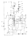
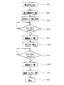
図1は、本発明の一実施例のフロー図である。有毒ガスの除害装置Yの液体槽1には、処理液、例えば、水Wが貯溜されている。この液体槽1には、その外部に液体槽1内の液Wを循環させるための循環路5が配置され、循環路5にはポンプ3、圧力計PIA−2、流量計F−2並びに気液混合・攪拌装置4が介装されている。ポンプ3は、インバーターIVの設定値により回転数が可変出来、流量及び圧力が調整できるように構成されている。
A first embodiment of the present invention will be described with reference to FIGS.
FIG. 1 is a flow diagram of one embodiment of the present invention. A treatment liquid, for example, water W is stored in the liquid tank 1 of the toxic gas abatement apparatus Y. The liquid tank 1 is provided with a
液体槽1には、液量が一定量、例えば、100リットル、を越えると、排液するようにオーバーフロー管9と、給水ライン8と、が設けられている。給水ライン8には、電磁弁10が介装され、通常は閉じているが、pH計7により検出される液体槽1内のpH値により電磁弁10が開き液体槽1内に給水するように構成されている。
The liquid tank 1 is provided with an
気液混合・攪拌装置4には、半導体製造装置や液晶製造装置からの排気を吸気するための吸気配管13が接続されている。吸気配管13には、上流側から下流側に向かって順次、自動三方弁2、圧力計PIA−1、自動バルブ12及び洗浄部6、が介装されている。
The gas-liquid mixing /
吸気配管13には、管内乾燥手段Dが設けられている。この乾燥手段Dは、前記バルブ12の上流側に接続された乾燥用気体配管16を備えており、この配管16には、上流側から下流側に向かって順次、流量調整用のニードルバルブ16n、流量計F−3及び電磁弁15、が介装されている。前記配管16の一部には、該配管16内を通る窒素Tを暖めるためのヒーター24が巻かれている。
The
管内洗浄手段である、洗浄部6には、給水ライン8から分岐してバルブ11を介して給水ができるように給水パイプ8aが接続されている。このバルブ11は、通常閉じられ、装置のメンテナンス時に必要に応じて作業者が該バルブ11を開き、洗浄可能な構成になっている。
A
液体槽1の上部には、排気口14が設けられている。この排気口14は、気液混合・攪拌装置4により混合攪拌されて液体槽1に達し、除害されたガス(処理済ガス)を排気するもので、生産ラインの排気配管14hと接続できるように構成されている。
An
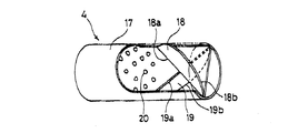
気液混合・攪拌装置4は、図2に示すように、円筒ケーシング17と、一対の二つ割り楕円盤18、19と、下流側に配置された突起群20と、から構成され、二つ割り楕円盤18、19の弦側側縁18a,19aを交差させ、一対の二つ割り楕円盤18、19の円弧側側縁18b、19bを円筒ケーシング17の内壁に接するように構成されている。
As shown in FIG. 2, the gas-liquid mixing /
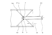
前記気液混合・攪拌装置4には、図3に示すように、ガス導入パイプ21が接続されているが、このガス導入パイプ21は、前記吸気配管13と一体となって有毒ガスを前記気液混合・撹拌装置4に導入するもので、いわば前記吸気配管13の一部をなしている。従って、吸気配管13の概念には、このガス導入パイプ21も含まれる。
As shown in FIG. 3, a
前記気液混合・撹拌装置4には、ポンプ3の運転により液体槽1内の液Wが送られ、前記二つ割り楕円盤18、19の作用により該液Wが螺旋流を起こしてガス導入パイプ21からのガスと混合されるが、突起群20の作用でガスGは、微細に砕かれ、液Wと混合するように構成されている。
The gas-liquid mixing /
次に、本実施例の作動について説明する。
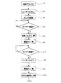
起動時、又は、再起動時:
起動ボタン(図示せず)をオンする(S1)と、ヒーター24がオンする(S2)と共に、ポンプ3が起動(S3)し液体槽1内の液Wを循環路5に回し始め、循環路5内の流量が略一定となる。
Next, the operation of this embodiment will be described.
When starting or restarting:
When the start button (not shown) is turned on (S1), the
予め定められた設定時間t1、例えば、t1=3秒、経過する(S4)と、前記バルブ12及び前記配管16の電磁弁15が開き(S5,S6)、暖められた窒素Tが吸気配管13に流入する。
When a predetermined set time t1, for example, t1 = 3 seconds elapses (S4), the
電磁弁15を開にした後、一定時間t2、例えば、t2=5分、経過する(S7)と、ヒーター24はオフとなり(S8)、電磁弁15は閉となる(S9)。
After a certain time t2, for example, t2 = 5 minutes, has elapsed after the
そうすると、吸気配管13の自動三方弁2が切り替わり(S10)、それまでバイパスB側に流入していた半導体製造装置や液晶製造装置からの有毒ガスGは、吸気配管13,ガス導入パイプ21を通り気液混合・撹拌装置4内に送り込まれる。
Then, the automatic three-
かかる起動時の作動により、本装置停止時に蒸発し、結露して吸気配管13の自動バルブ12の下流内壁に付着していた、水分を乾燥させる。
Due to the operation at the time of starting, the moisture that has evaporated and condensed when the apparatus is stopped and adhered to the downstream inner wall of the
前記バルブ12は、装置停止時には、閉じているため、蒸発した水分が前記バルブ12よりも上流側に付着することなく、水分と有毒ガスとの反応によって自動三方弁2が固着することもない。
Since the
又、吸気配管13の窒素導入口13aが前記バルブ12の上流側に位置しているため、効果的に乾燥させることができる。
Further, since the nitrogen inlet 13a of the
なお、乾燥用気体として、窒素Tを用いたが、必ずしもこれに限定されるものではなく、例えば、ドライエアー等を用いることもできる。又、乾燥を速めるためにヒーター24で窒素を加熱するが、充分な乾燥時間が取れるならば必ずしもヒーター24は必要ではない。
Although nitrogen T is used as the drying gas, it is not necessarily limited to this, and for example, dry air or the like can be used. In order to speed up drying, nitrogen is heated by the
前述の吸気管の乾燥動作により吸気配管13内壁やガス導入パイプ21内壁は、乾燥し水分が存在しないため、半導体製造装置や液晶製造装置からの有毒ガスGを流しても、従来例と異なり固形物やゲル状物質が前記内壁に付着することはない。又、有毒ガスGに含有する粉体も乾燥しているので、前記内壁に付着しにくいので、長時間の連続運転が可能となる。
Due to the drying operation of the intake pipe described above, the inner wall of the
気液混合・攪拌装置4内に送り込まれた液Wと有毒ガスGは、ガス導入パイプ21の出口21a近傍で接触するとともに、前述の作用により混合・攪拌され、ガスGは微細気泡、例えば、直径0.5〜3.0mmの気泡、となって液体槽1に戻され、除害される。
The liquid W and the toxic gas G fed into the gas-liquid mixing /
除害されたガス(処理済ガス)G0は、排気口14を通過し、排気配管14hを介して生産ライン(図示せず)に送り込まれる。この時、前記ガスG0は、排気口14を通過する際に、内部に冷却水cwが流れるチューブ14cと接触し、クリーンルーム(図示せず)内の温度以下に冷却される。そのため、余分な水分は、排気口14内で結露し、その結露は液体槽1内に戻されるので、排気配管14h内で結露することが無く、該排気配管14hのメンテナンスサイクルも従来例に比べ、大幅に長くすることができる。
The detoxified gas (treated gas) G0 passes through the
時間の経過と共に液体槽1内のガスの溶解濃度が増加していく。即ち、液体槽1内の液量は、100リットルに設定されており、塩素を200cc/分の割合で処理した場合、約20分後にはpH値が4以下となり徐々に除害効率が落ちてしまう。そのため、液体槽1内のpH値をpH計7で監視し、予め設定されたpH値を維持するように、給水ライン8に介装された電磁弁10を流量計F−1を見ながらオン・オフし、給水NWの制御を行っている。
The dissolved concentration of the gas in the liquid tank 1 increases with time. That is, the liquid volume in the liquid tank 1 is set to 100 liters, and when chlorine is treated at a rate of 200 cc / min, the pH value becomes 4 or less after about 20 minutes and the detoxification efficiency gradually decreases. End up. Therefore, the pH value in the liquid tank 1 is monitored by the
給水NWが開始されると、液体槽1内の液量が増加し、オーバーフロー管9より100リットルを越えた液HWは排液されるようになっている。かかる給排水機構の作用で時間が経過しても一定の除害効率が維持できるようになっている。
When the water supply NW is started, the amount of liquid in the liquid tank 1 increases, and the liquid HW exceeding 100 liters is discharged from the
本実施の形態では、pH値によって給排水を制御しているが、予め処理するガスの量が判っている場合には、タイマー設定により液の入れ替えを実施しても良い。 In the present embodiment, the water supply / drainage is controlled by the pH value. However, when the amount of gas to be processed is known in advance, the liquid may be replaced by a timer setting.
管内洗浄:
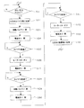
図7、図8により、運転中の吸気配管内の洗浄について説明する。
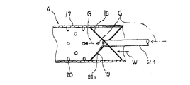
上記動作によりメンテナンスサイクルは、長くなるが、図7に示すようにガス導入パイプ21の出口21a近傍では、水分が存在するため、徐々に副生成物Fが管内壁に成長する。該管内壁の副生成物Fの成長に伴い、管内詰まり検出手段である、圧力計PIA−1により検出される圧力値は、徐々に上昇する(S21)。
In-tube cleaning:
With reference to FIGS. 7 and 8, the cleaning of the intake pipe during operation will be described.
Although the maintenance cycle becomes longer due to the above operation, by-product F gradually grows on the inner wall of the pipe because moisture is present in the vicinity of the
予め設定された圧力値P3、例えば、P3=-0.5kPa、に達すると、自動三方弁2がバイパスB側に切り替わる(S22)と共に自動バルブ12が閉じ(S23)、電磁弁11が開いて(S24)、水が洗浄部6を通り、ガス導入パイプ21に供給される。
When a preset pressure value P3, for example, P3 = −0.5 kPa, is reached, the automatic three-
本実施例では、10L/min.の水を流しており、その水圧により副生成物Fは管内壁から剥離し、除去される。水をT5、例えば、5秒流すと(S25),ヒータ24がオン(S26)し、電磁弁11は閉じ(S27)、水のガス導入パイプ21への供給は止められる。
In this example, 10 L / min. The by-product F is peeled off from the inner wall of the pipe and removed by the water pressure. When water is allowed to flow for T5, for example, 5 seconds (S25), the
その後T6、例えば3秒、が経過する(S28)と、自動バルブ12が開き(S29)、電磁弁15が開いて(S30)、乾燥用の暖められた窒素Tが吸気配管13に流入する。
Thereafter, when T6, for example, 3 seconds elapses (S28), the
電磁弁15を開にした後、一定時間t2、例えば、t2=5分、経過する(S31)と、ヒーター24はオフとなり(S32)、電磁弁15は閉となる(S33)。
そうすると、吸気配管13の自動三方弁2が切り替わり(S34)、それまでバイパスB側に流入していた半導体製造装置や液晶製造装置からの有毒ガスGは、吸気配管13,ガス導入パイプ21を通り気液混合・撹拌装置4内に送り込まれ、通常運転に復帰する。
After a certain time t2, for example, t2 = 5 minutes, has elapsed after the
Then, the automatic three-
かかる動作によって、ガス導入パイプ21の出口21a近傍に付着した副生成物Fは、自動的に除去されるため、メンテナンスサイクルは飛躍的に長くなる。
By this operation, the by-product F adhering to the vicinity of the
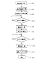
停止時:
図5に示すように、本装置Yの停止ボタン(図示せず)が押される(S11)と、給水電磁弁10が閉じ(S12)、自動三方弁2がバイパスB側に切り替わる(S13)。そのため、本装置YへのガスGの流入が止まるため、吸気配管13に配設された圧力計PIA−1で検出される圧力値は、低下する(S14)。
When stopped:
As shown in FIG. 5, when a stop button (not shown) of the apparatus Y is pressed (S11), the water supply
予め設定された圧力値P1、例えば、P1=-20kPa、に達すると、電磁弁15が開いて(S15)窒素Tが流入されると共に、ポンプ3が停止する(S16)。ポンプ3の停止により気液混合・撹拌装置4の吸引力が無くなるために、圧力計PIA−1で検出される圧力値は、供給される窒素Tによって上昇する。
When a preset pressure value P1, for example, P1 = -20 kPa, is reached, the
予め定めた圧力値P2、例えば、P2=0kPaになる(S17)と、電磁弁15を閉じて(S17)窒素供給を止めるとともに、前記バルブ12を閉じて(S19)、本装置Yを停止させる(S20)。なお、本実施の形態では、圧力計PIA−1の値によって電磁弁15を開閉しているが、図6に示すように、タイマー設定T3,T4(S24,S27)によって動作させても良く、又、併用でも良い。
When a predetermined pressure value P2, for example, P2 = 0 kPa (S17), the
かかる動作によって自動三方弁2がバイパスB側に切り替わった後、吸気配管13内に残った有毒ガスを除外する。又、通常運転時には、負圧になっている吸気配管13に停止時に液体槽1の液Wが逆流し、吸気配管13へ水分が付着するのを防でいる。
After the automatic three-
なお、本装置Yには、安全確保のために各種インターロックにより装置停止が働く様になるが、故障信号によって停止する際も前記図5、図6のフローに従って停止することは言うまでもない。 The apparatus Y is stopped by various interlocks to ensure safety. Needless to say, the apparatus Y is stopped according to the flow shown in FIGS.
1 液体槽
2 自動三方弁
4 気液混合撹拌装置
5 循環路
6 洗浄部
8 給水ライン
12 自動バルブ
13 吸気配管
14 排気口
14c チューブ
16 乾燥用気体配管
21 ガス導入パイプ
Y 有毒ガスの除害装置
DESCRIPTION OF SYMBOLS 1
12 Automatic valve
13 Intake piping
14 Exhaust vent
14c tube
16 Gas piping for drying
21 Gas introduction pipe Y Toxic gas abatement equipment
Claims (13)
前記吸気配管へ前記有毒ガスを導入する前に、該配管内に乾燥用気体を供給して管内乾燥を行うことを特徴とする有毒ガスの除害方法。 In the method of detoxification by mixing toxic gas introduced from the intake pipe into the water in the liquid tank;
Before introducing the toxic gas into the intake pipe, a drying gas is supplied into the pipe for drying in the pipe.
前記吸気配管へ洗浄流体を供給して管内洗浄を行う行程と、
前記管内洗浄完了後、前記配管内に乾燥用気体を供給して管内乾燥を行う行程と、
前記管内乾燥完了後、前記吸気配管へ前記有毒ガスを供給する行程と、
を備えていることを特徴とする有毒ガスの除害方法。 In the method of detoxification by mixing toxic gas introduced from the intake pipe into the water in the liquid tank;
A process of supplying cleaning fluid to the intake pipe and cleaning the pipe;
After completion of the in-pipe cleaning, a process of supplying a drying gas into the pipe and performing in-pipe drying;
A step of supplying the toxic gas to the intake pipe after completion of drying in the pipe;
A toxic gas abatement method comprising:
運転中に、前記吸気配管内の詰まり圧力を検出する行程と、
前記詰まり圧力検出時に、前記有毒ガスの供給を停止しすると共に、前記吸気配管へ洗浄流体を供給して管内洗浄を行う行程と、
前記管内洗浄完了後、前記吸気配管内に乾燥用気体を供給して管内乾燥を行う行程と、
前記管内乾燥完了後、前記吸気配管へ前記有毒ガスを導入し、通常運転に復帰する行程と、
を備えていることを特徴とする有毒ガスの除害方法。 In the method of detoxification by mixing toxic gas introduced from the intake pipe into the water in the liquid tank;
A process of detecting clogging pressure in the intake pipe during operation;
When the clogging pressure is detected, the supply of the toxic gas is stopped, and a cleaning fluid is supplied to the intake pipe to clean the pipe.
After the completion of the in-pipe cleaning, a step of supplying the drying gas into the intake pipe to perform in-pipe drying;
After completion of drying in the pipe, introducing the toxic gas into the intake pipe and returning to normal operation;
A toxic gas abatement method comprising:
前記吸気配管内を乾燥させる管内乾燥手段を備えていることを特徴とする有毒ガスの除害装置。 In a toxic gas removal device that removes toxic gas introduced from the intake pipe by mixing it with water in the liquid tank;
A poisonous gas removing apparatus comprising a pipe drying means for drying the inside of the intake pipe.
前記吸気配管内を乾燥させる管内乾燥手段と、
前記吸気管内を洗浄する管内洗浄手段と、
を備えていることを特徴とする有毒ガスの除害装置。 In a toxic gas removal device that removes toxic gas introduced from the intake pipe by mixing it with water in the liquid tank;
In-pipe drying means for drying the inside of the intake pipe;
In-pipe cleaning means for cleaning the inside of the intake pipe;
A toxic gas abatement device comprising:
運転中に、前記吸気配管内の圧力を検出する管内詰まり検出手段と、
前記管内詰まり検出手段の検出結果に基づき、前記吸気管内を洗浄する管内洗浄手段と、
前記管内洗浄完了後、前記吸気配管内を乾燥させる管内乾燥手段と、
を備えていることを特徴とする有毒ガスの除害装置。 In a toxic gas removal device that removes toxic gas introduced from the intake pipe by mixing it with water in the liquid tank;
In-clogging detection means for detecting the pressure in the intake pipe during operation,
In-pipe cleaning means for cleaning the inside of the intake pipe based on the detection result of the in-pipe clogging detection means,
In-pipe drying means for drying the inside of the intake pipe after completion of the pipe cleaning,
A toxic gas abatement device comprising:
前記吸気配管内を乾燥させるための気体を流入させる乾燥用配管と、該気体の流入を制御する弁とを有し、
少なくとも装置起動時、若しくは、再起動時に、該気体を前記吸気配管内に流入せしめ、その後に有毒ガスを導入することを特徴とする有毒ガスの除害装置。 In a device that removes toxic gas introduced from the intake pipe by mixing it with water;
A drying pipe for introducing a gas for drying the inside of the intake pipe, and a valve for controlling the inflow of the gas;
A poisonous gas abatement apparatus characterized by causing the gas to flow into the intake pipe and then introducing a toxic gas at least when the apparatus is activated or restarted.
前記吸気配管内を洗浄させるための液体を流入させる洗浄用配管と、該液体の流入を制御する弁とを有し、
吸気圧力上昇時には、有毒ガスの流入を制限して前記液体を前記吸気配管内に流入せしめて管内洗浄し、その後、管内乾燥手段により前記吸気配管内を乾燥させて管内乾燥した後、有毒ガスを再度導入するようにしたことを特徴とする有毒ガスの除害装置。 An apparatus for detoxifying by mixing toxic gas introduced from an intake pipe into water, a drying pipe for introducing a gas for drying the inside of the intake pipe, and a valve for controlling the inflow of the gas In the toxic gas abatement device possessed;
A cleaning pipe for introducing a liquid for cleaning the inside of the intake pipe, and a valve for controlling the inflow of the liquid;
When the intake pressure rises, the inflow of toxic gas is restricted and the liquid is allowed to flow into the intake pipe to clean the inside of the pipe. A poisonous gas abatement device characterized by being introduced again.
前記吸気配管内を乾燥させる管内乾燥手段と、
前記排気口内の処理済ガスを冷却するガス冷却手段と、
を備えていることを特徴とする有毒ガスの除害装置。 A liquid tank for storing the processing liquid, a gas-liquid mixing / stirring device provided in the liquid tank, an exhaust port provided in the upper part of the liquid tank, and a processing of the liquid tank in the gas-liquid mixing / stirring device A toxic gas abatement apparatus comprising: a circulation path for supplying a liquid; and an intake pipe for sucking the toxic gas into the gas-liquid mixing / stirring device;
In-pipe drying means for drying the inside of the intake pipe;
Gas cooling means for cooling the treated gas in the exhaust port;
A toxic gas abatement device comprising:
7. The toxic gas abatement apparatus according to claim 5, wherein the in-pipe cleaning means is a cleaning section provided between the automatic valve of the intake pipe and the gas introduction pipe.
Priority Applications (1)
| Application Number | Priority Date | Filing Date | Title |
|---|---|---|---|
| JP2004228351A JP2005296918A (en) | 2004-03-15 | 2004-08-04 | Method for detoxifying poisonous gas and its apparatus |
Applications Claiming Priority (2)
| Application Number | Priority Date | Filing Date | Title |
|---|---|---|---|
| JP2004072386 | 2004-03-15 | ||
| JP2004228351A JP2005296918A (en) | 2004-03-15 | 2004-08-04 | Method for detoxifying poisonous gas and its apparatus |
Publications (1)
| Publication Number | Publication Date |
|---|---|
| JP2005296918A true JP2005296918A (en) | 2005-10-27 |
Family
ID=35329107
Family Applications (1)
| Application Number | Title | Priority Date | Filing Date |
|---|---|---|---|
| JP2004228351A Pending JP2005296918A (en) | 2004-03-15 | 2004-08-04 | Method for detoxifying poisonous gas and its apparatus |
Country Status (1)
| Country | Link |
|---|---|
| JP (1) | JP2005296918A (en) |
Cited By (3)
| Publication number | Priority date | Publication date | Assignee | Title |
|---|---|---|---|---|
| WO2009084696A1 (en) * | 2007-12-28 | 2009-07-09 | Ryncosmos, Llc. | Method of removing harmful substances |
| JP2011125816A (en) * | 2009-12-18 | 2011-06-30 | Tosetsu:Kk | Gas-liquid mixture stirring device |
| JP2012210572A (en) * | 2011-03-31 | 2012-11-01 | Tosetsu:Kk | Gas liquid mixing stirring device |
Citations (3)
| Publication number | Priority date | Publication date | Assignee | Title |
|---|---|---|---|---|
| JP2001176854A (en) * | 1999-12-16 | 2001-06-29 | Sumitomo Seika Chem Co Ltd | System for processing exhaust gas of dry etching |
| JP2002530576A (en) * | 1998-11-25 | 2002-09-17 | ユニヴァーシティー オブ ダンディー | Method and apparatus for removing particulate matter |
| JP2002346336A (en) * | 2001-05-28 | 2002-12-03 | Tousetsu:Kk | Apparatus for detoxifying poisonous gas |
-
2004
- 2004-08-04 JP JP2004228351A patent/JP2005296918A/en active Pending
Patent Citations (3)
| Publication number | Priority date | Publication date | Assignee | Title |
|---|---|---|---|---|
| JP2002530576A (en) * | 1998-11-25 | 2002-09-17 | ユニヴァーシティー オブ ダンディー | Method and apparatus for removing particulate matter |
| JP2001176854A (en) * | 1999-12-16 | 2001-06-29 | Sumitomo Seika Chem Co Ltd | System for processing exhaust gas of dry etching |
| JP2002346336A (en) * | 2001-05-28 | 2002-12-03 | Tousetsu:Kk | Apparatus for detoxifying poisonous gas |
Cited By (4)
| Publication number | Priority date | Publication date | Assignee | Title |
|---|---|---|---|---|
| WO2009084696A1 (en) * | 2007-12-28 | 2009-07-09 | Ryncosmos, Llc. | Method of removing harmful substances |
| JP2009160492A (en) * | 2007-12-28 | 2009-07-23 | Ryncosmos Llc | Method of removing harmful substances |
| JP2011125816A (en) * | 2009-12-18 | 2011-06-30 | Tosetsu:Kk | Gas-liquid mixture stirring device |
| JP2012210572A (en) * | 2011-03-31 | 2012-11-01 | Tosetsu:Kk | Gas liquid mixing stirring device |
Similar Documents
| Publication | Publication Date | Title |
|---|---|---|
| JP2003305348A (en) | Ozone water generation system and method for controlling the same | |
| JP2010516458A (en) | Filter module drain / flush sequence and system | |
| US11219868B2 (en) | Device for cleaning and method for cleaning water treatment membrane, and water treatment system | |
| JP4564529B2 (en) | Drain pipe cleaning method and drain pipe cleaning device | |
| KR102024871B1 (en) | Device for removing residual ozone gas | |
| JPH08281039A (en) | Air cleaner | |
| WO2006087899A1 (en) | Dry cleaning apparatus | |
| JP2005296918A (en) | Method for detoxifying poisonous gas and its apparatus | |
| JP4850350B2 (en) | Toxic gas removal method and apparatus | |
| JP4805463B2 (en) | Toxic gas abatement equipment | |
| JP2004130205A (en) | Backwashing method and backwashing device for filtration membrane using ozone-containing water | |
| JP2006116388A (en) | Air diffuser and operation method of air diffuser | |
| JP4348691B2 (en) | How to prevent clogging of reverse osmosis membrane | |
| JP4215584B2 (en) | Oil / water separator | |
| KR102611042B1 (en) | A semiconductor waste gas treatment scrubber that has both the desorption and discharge functions of the adhering powder | |
| JP2796996B2 (en) | Bathtub sterilization method | |
| JP2003273061A (en) | Treating method and treating system | |
| JP3009688B2 (en) | Bathtub cleaning equipment | |
| JP6543493B2 (en) | Water treatment equipment | |
| JP3132032U (en) | Ejector and abatement device | |
| JP2529203Y2 (en) | Bath jet equipment | |
| JP4691531B2 (en) | Gas purification method and gas purification device | |
| JP2012147743A (en) | Apparatus for treating living tissue | |
| JP2006187728A (en) | Air diffuser | |
| JP2009248018A (en) | Wet detoxification method and its apparatus |
Legal Events
| Date | Code | Title | Description |
|---|---|---|---|
| A621 | Written request for application examination |
Free format text: JAPANESE INTERMEDIATE CODE: A621 Effective date: 20070727 |
|
| A977 | Report on retrieval |
Free format text: JAPANESE INTERMEDIATE CODE: A971007 Effective date: 20081219 |
|
| A131 | Notification of reasons for refusal |
Free format text: JAPANESE INTERMEDIATE CODE: A131 Effective date: 20100601 |
|
| A521 | Written amendment |
Free format text: JAPANESE INTERMEDIATE CODE: A523 Effective date: 20100712 |
|
| A02 | Decision of refusal |
Free format text: JAPANESE INTERMEDIATE CODE: A02 Effective date: 20100817 |