JP2005296912A - Scum removal apparatus - Google Patents
Scum removal apparatus Download PDFInfo
- Publication number
- JP2005296912A JP2005296912A JP2004142944A JP2004142944A JP2005296912A JP 2005296912 A JP2005296912 A JP 2005296912A JP 2004142944 A JP2004142944 A JP 2004142944A JP 2004142944 A JP2004142944 A JP 2004142944A JP 2005296912 A JP2005296912 A JP 2005296912A
- Authority
- JP
- Japan
- Prior art keywords
- trough
- weir
- scum
- water surface
- water
- Prior art date
- Legal status (The legal status is an assumption and is not a legal conclusion. Google has not performed a legal analysis and makes no representation as to the accuracy of the status listed.)
- Granted
Links
- XLYOFNOQVPJJNP-UHFFFAOYSA-N water Substances O XLYOFNOQVPJJNP-UHFFFAOYSA-N 0.000 claims abstract description 32
- 230000007246 mechanism Effects 0.000 claims abstract description 12
- 238000004062 sedimentation Methods 0.000 claims abstract description 10
- 238000005273 aeration Methods 0.000 claims abstract description 4
- 239000002184 metal Substances 0.000 claims abstract description 4
- 239000000463 material Substances 0.000 claims description 4
- 241000167880 Hirundinidae Species 0.000 claims 1
- 238000005192 partition Methods 0.000 description 6
- 238000005452 bending Methods 0.000 description 2
- 238000004891 communication Methods 0.000 description 1
- 238000000034 method Methods 0.000 description 1
- 239000011347 resin Substances 0.000 description 1
- 229920005989 resin Polymers 0.000 description 1
- 230000000630 rising effect Effects 0.000 description 1
- 229910001220 stainless steel Inorganic materials 0.000 description 1
- 239000010935 stainless steel Substances 0.000 description 1
Images
Landscapes
- Removal Of Floating Material (AREA)
Abstract
Description
本発明は、沈澱池や曝気槽などの処理池内に構成されて水面に浮ぶスカムを誘引・除去するためのスカム除去装置に関する。 The present invention relates to a scum removing device for attracting / removing scum formed in a processing pond such as a sedimentation pond or an aeration tank and floating on a water surface.
例えば、矩形をした沈澱池内には、水面の浮遊物であるスカムを誘引除去するためのスカム除去装置が設置されるが、同装置は、トラフと堰を備える。トラフは、中心軸回りに前後に回転してスカムの呑み込みと堰き止めを交互に行うスカムスキマーがあるが、ここでは、トラフが固定式のものである。同トラフは、J形断面でその低い一側が水面より低く設定され高い部分が水面より上方にあるようにして水面を境にして左右の側壁間に固定して横架されることでスカムが水とともにその長手方向に流れるようにされた金属製あるいはコンクリート製などでなるものである。堰は、トラフの前記一側に浮沈運動可能に設けられて浮上した堰止め状態から沈降することで水面上に浮遊のスカムを水とともに呑み込み前記トラフ内に流入させるようにするものである。そして、トラフ上には、前後中間を横軸支点にして動く作動アームが設けられ、この作動アームの後端を池上に固定した電動シリンダなどの駆動装置により持ち上げることにより同アームの前端に連結した堰を押し下げるようにする一方、押し下げられた堰は、駆動装置による作動アームの押し下げにより逆に浮上するものである。この際、堰はそれ自体のもつ浮上力で浮上復帰も可能とされている。 For example, a scum removing device for attracting and removing scum, which is floating on the water surface, is installed in a rectangular sedimentation basin, and the device includes a trough and a weir. The trough has a scum skimmer that rotates back and forth around the central axis and alternately scums and dams the scum. Here, the trough is fixed. The trough has a J-shaped cross section with its lower side set lower than the water surface and the higher part above the water surface. In addition, it is made of metal or concrete made to flow in the longitudinal direction. The weir is provided on the one side of the trough so as to be capable of floating and sinking, and sinks from the suspended state where it floats, so that the floating scum is swallowed together with water and flows into the trough. On the trough, an operating arm is provided that moves around the horizontal axis as the fulcrum. The rear end of the operating arm is connected to the front end of the arm by lifting it with a driving device such as an electric cylinder fixed on the pond. While the weir is pushed down, the pushed-down weir rises conversely when the operating arm is pushed down by the driving device. At this time, the weir can be lifted and returned by its own floating force.
ところで、前記作動アーム上には、手動アームが池上に延びるように設けられて、駆動装置とは別に堰を沈降方向に作動させることが可能になっている。一方、トラフ前の堰は、トラフと同様長さでこれまでの一般長さは4m前後のものであったが、沈澱池の幅によっては、7〜8mと長くなるものもあり、その場合に堰をトラフと同様に単一本の長いままにしておくと、堰に過大な水圧が作動するため、手動アームで作動させることが無理になってきた。そのためには、堰を分割して個別に手動アームで作動させるようにすればよいのであるが、個別に作動させるようにすると、逆に本作動である駆動装置による作動も個別化して複数の駆動装置を構成する必要がでてきた。
上記に鑑み、本発明は、駆動装置は単一個のままで手動アームの操作を軽快に行うことができるようにしたスカム除去装置を提供することを目的とする。By the way, a manual arm is provided on the operating arm so as to extend on the pond, and the weir can be operated in the settling direction separately from the driving device. On the other hand, the weir before the trough was the same length as the trough, and the general length so far was around 4m, but depending on the width of the sedimentation basin, there are some that become as long as 7-8m. If the weir is left as long as a single trough, excessive water pressure will act on the weir, making it impossible to operate with a manual arm. To that end, it is only necessary to divide the weirs and individually operate them with the manual arm. However, if the individual weirs are operated individually, the operation by the driving device, which is the main operation, is also individualized and a plurality of driving is performed. It has become necessary to configure the device.
In view of the above, an object of the present invention is to provide a scum removing device that can easily operate a manual arm with a single driving device.
上記課題を解決するため、請求項1記載の発明は、少なくとも一側が沈澱池や曝気槽などの処理池内の水面より低く設定されて同水面を境にして固定して両側壁間に横架されることでスカムが水とともにその長手方向に流れるようにされた金属製あるいはコンクリート製などでなる樋状で長尺状をなす単一本のトラフと、同トラフの前記一側に浮沈運動可能に設けられて浮上した堰止め状態から沈降することで水面上に浮遊のスカムを水とともに呑み込み前記トラフ内に流入させるようにする堰と、この堰を連動させるべく設けられた駆動装置と、前記堰を沈降作動させるために立設される手動アームとを備えたスカム除去装置であって、前記堰は、単一本のトラフに対し、前記長手方向に対応して左右に分割状で独立した作動が可能に配備されて、両堰が一方向連動機構を介して前記駆動装置により同時に連動可能である一方手動アームにより個別に独立しても連動可能にもなっていることを特徴とする。
請求項2記載の発明は、請求項1記載のものにおいて、一方向連動機構は、ワイヤーロープ・リンクチェーン・プレートチェーンなどの条材を備える。In order to solve the above-mentioned problem, the invention according to claim 1 is characterized in that at least one side is set lower than the water surface in a treatment pond such as a sedimentation basin or an aeration tank, and is fixed across the water surface and is placed between both side walls. This allows the scum to move along with water in the longitudinal direction of a single trough that is made of metal or concrete, and has a long and slender shape. A weir that sinks floating scum with water and flows into the trough by sinking from a dammed state that has been levitated and provided, a driving device provided to interlock the weir, and the weir A scum removing device having a manual arm that is erected in order to cause a settling operation, wherein the weir is independent of a single trough and is divided into left and right parts corresponding to the longitudinal direction. Can be deployed Is in both weir, characterized in that it is also the possible cooperation be independently separately by one manipulation arm can be interlocked simultaneously by said driving device through a one-way interlocking mechanism.
According to a second aspect of the present invention, in the first aspect, the one-way interlocking mechanism includes a strip material such as a wire rope, a link chain, and a plate chain.
本発明によれば、駆動装置は単一個のままで手動アームの操作を軽快に行うことができるようにしたスカム除去装置を提供することができる。 According to the present invention, it is possible to provide a scum removing device in which the manual arm can be easily operated with a single drive device.
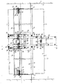
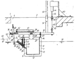
図1および図2は、本発明に係るスカム除去装置の一実施形態を示す。図1および図2に示すように、1は矩形の沈澱池(処理池)で、図1の上下に示す側壁2,2は沈澱池1の左右に対応し、その間隔は約7.8mとされ、図1および図2の左右に対応する方向は数十mの長いものである。3は上壁で、図示個所には開口4が開けられている。 1 and 2 show an embodiment of a scum removing device according to the present invention. As shown in FIGS. 1 and 2, reference numeral 1 denotes a rectangular sedimentation basin (treatment pond), and the
図1の6,6は連動トラフで、各側壁2に挿通固定されている。これらの連通トラフ6,6間にそれぞれフランジ7を介してトラフ8が横架固定されている。このトラフ8は、図2のように断面がJ形をなす角型のもので、その一側(前側)の前壁9は、水面10よりも低くされてその前端に前縁部11が形成される一方、前壁9の下端からは水平な底壁12が一体折り曲げにて形成され、かつ、底壁12の後端からは同じく一体折り曲げにより垂直な後壁13が上部を水面10より突き出す形で設けられている。14は上端フランジである。 Reference numerals 6 and 6 in FIG. 1 denote interlocking troughs that are inserted and fixed to the
こうしたトラフ8は、単一本でその長手方向の長さが略7.4mで、従来のもの(4m前後のもの)より2倍弱の非常に長いものとされている。同トラフ8は従来のものに比し2倍半あるいは3倍…のように超ロングタイプの場合もある。 Such a
トラフ8の前縁部11には、左右両端位置にトラフ8側の端部固定仕切り板16,16が固定されるとともに、長手方向中間を挟む左右に一定寸法離間する位置には、同じく上方に立ち上がる中央固定仕切り板17が左右一対固定されている。各中央固定仕切り板17は、前縁部11から立ち上がるアングル型の中央支柱18を介しても固定されている。 On the
20は堰で、図1に示すように、中間を離間させた状態で左右一対分割式に設けられている。この堰20は、図2のような矩形断面をした偏平中空体でそれ自体が浮力を発生するものでなり、その両端に略三角形(扇形)をした端板21を溶接一体化させて内部が密閉されるとともに内部には浸水した際にも浮力が確約されるように発泡樹脂22が充填されてなる。そして、端板21は、同板面に直交する可動仕切り板23を備え、これら可動仕切り板23は、それぞれ前記した固定仕切り板16,17の前方において離間して対向状とされ、その間には、図1のように蛇行状をしたゴム製の側部シール24…が介装固定されている。これらのシール24により堰20が浮沈運動しても前後に弾性変形しながら前方からの水を堰き止めた状態に維持する。また、堰20は、それぞれ両端の回転支持軸25を介して浮沈運動するとともに、前縁部11に取り付けられ同縁部11から斜め前方へ向けて伸びたゴム製の前部シール26に連結されて前方からの水の浸入を阻止しながら弾性変形をするものになっている。
中央支柱18の上端と後壁13の上端との間には、左右一対をなす渡架材27が渡されるとともに、これら渡架材27を介して左右対向状に突設された受材28間には、アーム軸29が通されてその外周の左右一対のアームパイプ30が独立して回転可能に設けられている。各アームパイプ30には、作動アーム32が上下に回転運動するように設けられている。作動アーム32は、図2のように、その後側にストッパ33を備えて上端フランジ14上に当って水平に規定するようになっている。ストッパ33は上下調節可能なタイプとされている。 Between the upper end of the
作動アーム32の先端には、板軸35が設けられてクラッチ板36が回転自在に支持されるとともに、同クラッチ板36は、図2において左回りに付勢されるように板軸35回りにバネ37を備える。そして、クラッチ板36には、通孔が開けられ、同通孔にはロッド38が挿通されている。ロッド38は、堰20の端部前底から突出するブラケット39に回転自在に連結されるとともに、クラッチ板36の通孔を挟む上下に前後をなして配備された係合板40に係脱自在とされている。受材28からは前方に向けてステー41が突設され、同ステー41の前端に備えた押さえストッパ42によりクラッチ板36の後端が押さえ付けられるようになっている。 A
一方、池上壁3上には、架台43が設けられ、同架台43には、駆動源44である電動シリンダが上下にロッド45を作用させるように取り付けられている。駆動源44およびロッド45は単一本であるが、ロッド45の下端には、水平な中継板46が設けられるとともに、中継板46の左右両端と各作動アーム32間には、ワイヤ(リンクチェーンやプレートチェーンなどでもよい)でなる線条材47が連結されて一方向連動機構48が構成されている。作動アーム32の後端より少し前寄りには、それぞれ手動アーム50を差し込むアーム受パイプ51が設けられている。 On the other hand, a gantry 43 is provided on the pond wall 3, and an electric cylinder, which is a drive source 44, is attached to the gantry 43 so that a
図1および図2は、左右の堰20,20の上部が水面10より浮き出したスカム堰き止め状態を示している。この状態では、線条材47が緩み、作動アーム32が図2の右回りに重力付勢されてストッパ33がトラフ8上に当った状態にあるとともに堰20は浮力で浮上しロッド38はクラッチ板36の通孔内で自由に上下できる状態にある。この自由に上下できる状態は、作動アーム32が水平でしかも左回りに付勢されたクラッチ板36が押さえストッパ42により水平に押さえ付けられていることにより前後の係合板40に係合していないことから得られる。この状態では、水面10の上下変動があってもロッド38が上下に自由に動くことができるので堰20は水位に追従することができる。 1 and 2 show a scum damming state in which the upper portions of the left and
一方、駆動源44の作動によりロッド45が引き上げられると、中継板46を介して左右の線条材47が引き上げられ、これにより、左右の作動アーム32はその後部を同時に持ち上げられ、逆に前部は下げられるようになる。作動アーム32の前部が下がりはじめると、クラッチ板36の後端が押さえストッパ42から外れ始めると同時にバネ37の作用でクラッチ板36が図2の左回りに持ち上げられるので、係合板40がロッド38の表面に係合するようになる。その結果、作動アーム32の前部がそれ以上下がるとロッド38が押し下げられて堰20は水面10より没することになり、堰20が水面10から数cm下がることで、水面のスカムが水とともに堰20上を通過してトラフ8内に誘引されることになる。トラフ8内に誘引されたスカム水は、底壁12が長手方向一方向に低くなっているので、低い方向へと流されて処理される。 On the other hand, when the
駆動源44によりロッド45が下がると、線条材47が緩み、作動アーム32は水平に戻される。その際、堰20の浮力や作動アーム32が後部を重くしていることで、堰20から作動アーム32が復帰するが、クラッチ板36が押さえストッパ42に当って図2の左回りに押さえ付けられることで水平に付勢されてその時点でロッド38と係合板40との係合関係はなくなる。 When the
一方、こうした作動では左右の堰20,20が同時に作動するが、手動アーム50が差し込まれて図2の左回りに操作されたときは、左右の手動アーム50,50は個別に独立して操作することができる。すなわち、線条材47が左右で独立して緩むことができる一方向連動機構48を採用するからである。 On the other hand, in such an operation, the left and
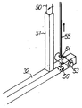
図3は他の実施形態を示す。作動アーム32の後端に横軸53を回転自在に備えてその孔54内にロッド状の線条材55を挿通して上下し得るように構成したものである。線条材55の下端には、持ち上げた際に横軸53に係合するように当り56を備え付けてある。 FIG. 3 shows another embodiment. A
尚、図2に仮想線で示すように、定支点軸60回りにアーム61を備え、同アーム61の後端に一方向連動機構62を介して作動アーム32の先端に結合してもよい。この場合、アーム61の左側の先端には、下向き湾曲状に突出する板材や曲げパイプなどの連動部材を備えて、池内で循環駆動するフライトにこの連動部材が持ち上げられることで作動アーム32が引下げられるように構成することができる。この方式では、駆動源44などは省略する。
また、前記トラフ8は、ステンレス製とされるが、現場の都合でコンクリートトラフになることもある。
さらに、トラフ8は、多少断面形状をすることがある。
また、堰20は、前記実施形態では2分割であったが、3分割以上でもよい。
さらに、前記実施形態では、クラッチ機構を介して堰20を作動させるものであったが、クラッチ機構のないものでもよい。
また、堰20は1枚板状など他の形状でもよい。
さらに、一方向連動機構48、62は、例えば、ワイヤのみで構成していたが、ワイヤとロッドを組み合わせたり、折れ曲がり自在な複数本のロッドにて構成することもできる。2, an
Although the
Furthermore, the
Moreover, although the
Furthermore, in the said embodiment, although the
The
Furthermore, although the one-
1 沈澱池
2 側壁
8 トラフ
9 前壁
10 水面
20 堰
32 作動アーム
44 駆動源
48,62 一方向連動機構DESCRIPTION OF SYMBOLS 1
Claims (2)
Priority Applications (1)
| Application Number | Priority Date | Filing Date | Title |
|---|---|---|---|
| JP2004142944A JP4437208B2 (en) | 2004-04-08 | 2004-04-08 | Scum remover |
Applications Claiming Priority (1)
| Application Number | Priority Date | Filing Date | Title |
|---|---|---|---|
| JP2004142944A JP4437208B2 (en) | 2004-04-08 | 2004-04-08 | Scum remover |
Publications (2)
| Publication Number | Publication Date |
|---|---|
| JP2005296912A true JP2005296912A (en) | 2005-10-27 |
| JP4437208B2 JP4437208B2 (en) | 2010-03-24 |
Family
ID=35329102
Family Applications (1)
| Application Number | Title | Priority Date | Filing Date |
|---|---|---|---|
| JP2004142944A Expired - Fee Related JP4437208B2 (en) | 2004-04-08 | 2004-04-08 | Scum remover |
Country Status (1)
| Country | Link |
|---|---|
| JP (1) | JP4437208B2 (en) |
Cited By (2)
| Publication number | Priority date | Publication date | Assignee | Title |
|---|---|---|---|---|
| CN105366763A (en) * | 2015-11-10 | 2016-03-02 | 安庆柳溪工业设备有限公司 | Slag scraper |
| KR102411599B1 (en) * | 2022-02-18 | 2022-06-22 | (주)동일캔바스엔지니어링 | Floatable scum skimmer |
-
2004
- 2004-04-08 JP JP2004142944A patent/JP4437208B2/en not_active Expired - Fee Related
Cited By (2)
| Publication number | Priority date | Publication date | Assignee | Title |
|---|---|---|---|---|
| CN105366763A (en) * | 2015-11-10 | 2016-03-02 | 安庆柳溪工业设备有限公司 | Slag scraper |
| KR102411599B1 (en) * | 2022-02-18 | 2022-06-22 | (주)동일캔바스엔지니어링 | Floatable scum skimmer |
Also Published As
| Publication number | Publication date |
|---|---|
| JP4437208B2 (en) | 2010-03-24 |
Similar Documents
| Publication | Publication Date | Title |
|---|---|---|
| US4693821A (en) | Weir for waste water treatment systems | |
| JP4437208B2 (en) | Scum remover | |
| JP4603211B2 (en) | Lifting overflow dam | |
| JP2006021181A (en) | Scum skimming apparatus | |
| KR100627641B1 (en) | Sedimentation basin with improved sedimentation efficiency | |
| JP2012024748A (en) | Scum removing device | |
| JP2606630Y2 (en) | Scum scraping device | |
| JP5895268B2 (en) | Scum remover | |
| JP2008260007A (en) | Scum removing device | |
| JP4055193B2 (en) | Float removal device | |
| JPH0220072Y2 (en) | ||
| JP2004283814A (en) | Suspension removal device | |
| JP4522319B2 (en) | Scum remover | |
| JP2585537Y2 (en) | Scum removal equipment for treatment ponds such as oxygenation | |
| JPH1115U (en) | Scum removal device | |
| JP2803024B2 (en) | Back rake type automatic dust remover | |
| JP2532560Y2 (en) | Scum processing device | |
| JPH10263U (en) | Scum removal device | |
| JP3959751B2 (en) | Scum remover | |
| JP2008212899A (en) | Scum remover | |
| JPH08257556A (en) | Scum removal device | |
| JPH0737390U (en) | Scum removal device | |
| CN119980848A (en) | A municipal bridge water discharge device | |
| JPH0645686U (en) | Scum pulling device | |
| JPH1085737A (en) | Suspended matter removal device |
Legal Events
| Date | Code | Title | Description |
|---|---|---|---|
| A621 | Written request for application examination |
Free format text: JAPANESE INTERMEDIATE CODE: A621 Effective date: 20070402 |
|
| A521 | Written amendment |
Free format text: JAPANESE INTERMEDIATE CODE: A523 Effective date: 20080411 |
|
| A977 | Report on retrieval |
Free format text: JAPANESE INTERMEDIATE CODE: A971007 Effective date: 20091124 |
|
| TRDD | Decision of grant or rejection written | ||
| A01 | Written decision to grant a patent or to grant a registration (utility model) |
Free format text: JAPANESE INTERMEDIATE CODE: A01 Effective date: 20091201 |
|
| A01 | Written decision to grant a patent or to grant a registration (utility model) |
Free format text: JAPANESE INTERMEDIATE CODE: A01 |
|
| A61 | First payment of annual fees (during grant procedure) |
Free format text: JAPANESE INTERMEDIATE CODE: A61 Effective date: 20091208 |
|
| FPAY | Renewal fee payment (event date is renewal date of database) |
Free format text: PAYMENT UNTIL: 20130115 Year of fee payment: 3 |
|
| R150 | Certificate of patent or registration of utility model |
Ref document number: 4437208 Country of ref document: JP Free format text: JAPANESE INTERMEDIATE CODE: R150 Free format text: JAPANESE INTERMEDIATE CODE: R150 |
|
| FPAY | Renewal fee payment (event date is renewal date of database) |
Free format text: PAYMENT UNTIL: 20140115 Year of fee payment: 4 |
|
| R250 | Receipt of annual fees |
Free format text: JAPANESE INTERMEDIATE CODE: R250 |
|
| R250 | Receipt of annual fees |
Free format text: JAPANESE INTERMEDIATE CODE: R250 |
|
| S111 | Request for change of ownership or part of ownership |
Free format text: JAPANESE INTERMEDIATE CODE: R313113 |
|
| R350 | Written notification of registration of transfer |
Free format text: JAPANESE INTERMEDIATE CODE: R350 |
|
| R250 | Receipt of annual fees |
Free format text: JAPANESE INTERMEDIATE CODE: R250 |
|
| R250 | Receipt of annual fees |
Free format text: JAPANESE INTERMEDIATE CODE: R250 |
|
| R250 | Receipt of annual fees |
Free format text: JAPANESE INTERMEDIATE CODE: R250 |
|
| R250 | Receipt of annual fees |
Free format text: JAPANESE INTERMEDIATE CODE: R250 |
|
| R250 | Receipt of annual fees |
Free format text: JAPANESE INTERMEDIATE CODE: R250 |
|
| LAPS | Cancellation because of no payment of annual fees |