JP2005296900A - Optical semiconductor catalyst-supporting fiber, air filter, air conditioner, heat exchange element, and heat exchange unit - Google Patents
Optical semiconductor catalyst-supporting fiber, air filter, air conditioner, heat exchange element, and heat exchange unit Download PDFInfo
- Publication number
- JP2005296900A JP2005296900A JP2004120840A JP2004120840A JP2005296900A JP 2005296900 A JP2005296900 A JP 2005296900A JP 2004120840 A JP2004120840 A JP 2004120840A JP 2004120840 A JP2004120840 A JP 2004120840A JP 2005296900 A JP2005296900 A JP 2005296900A
- Authority
- JP
- Japan
- Prior art keywords
- heat exchange
- air
- filter
- fiber
- exchange element
- Prior art date
- Legal status (The legal status is an assumption and is not a legal conclusion. Google has not performed a legal analysis and makes no representation as to the accuracy of the status listed.)
- Pending
Links
- 0 CCCC(CCN)C** Chemical compound CCCC(CCN)C** 0.000 description 1
Images


Landscapes
- Disinfection, Sterilisation Or Deodorisation Of Air (AREA)
- Exhaust Gas Treatment By Means Of Catalyst (AREA)
- Air Filters, Heat-Exchange Apparatuses, And Housings Of Air-Conditioning Units (AREA)
- Filtering Materials (AREA)
- Catalysts (AREA)
- Central Air Conditioning (AREA)
Abstract
【課題】 本発明の課題は、高価な特殊バインダを使用せずに安価に製造することができる光半導体触媒担持繊維を提供することにある。
【解決手段】 光半導体触媒担持繊維834は、光触媒機能を有するアパタイト835を担持する。
【選択図】 図9PROBLEM TO BE SOLVED: To provide an optical semiconductor catalyst-supporting fiber that can be produced at low cost without using an expensive special binder.
An optical semiconductor catalyst-supporting fiber 834 supports an apatite 835 having a photocatalytic function.
[Selection] Figure 9
Description
本発明は、光半導体触媒担持繊維、エアフィルタ、空気調和装置、熱交換エレメント、および熱交換ユニットに関する。 The present invention relates to an optical semiconductor catalyst-supporting fiber, an air filter, an air conditioner, a heat exchange element, and a heat exchange unit.
従来、酸化チタンなどの光半導体触媒が繊維などに担持され、空清フィルタ用途などに展開されている。ところで、光半導体触媒はバンドギャップ以上のエネルギーをもつ光(例えば、紫外線など)が照射されると、荷電子帯にある電子が伝導帯に励起され、荷電子帯に正孔が、伝導体に電子が生成する。その結果、荷電子帯側では酸化反応が、伝導体側では還元反応が起こりやすくなる。そして、この状態で空気や水などが光半導体触媒の表面に接触すると化学反応が起こり、OH−、O2、O2 −、およびH2O2などの活性酸素が生成される。すると、その活性酸素は、光半導体触媒の近傍に存在する種々の有機物を分解する。つまり、このような光半導体触媒をそのまま有機繊維に担持した場合、光半導体触媒が活性化されると自身を担持する有機繊維を浸食することなる(例えば、特許文献1参照)。したがって、光半導体触媒を有機繊維に担持する場合、通常、光半導体触媒の表面を有機繊維に接触させないようにするために、特殊なバインダを必要とする(例えば、特許文献2参照)。
しかし、このような特殊バインダは、コスト高を招く大きな要因となる。
本発明の課題は、高価な特殊バインダを使用せずに安価に製造することができる光半導体触媒担持繊維を提供することにある。
However, such a special binder is a major factor incurring high costs.
An object of the present invention is to provide an optical semiconductor catalyst-supporting fiber that can be manufactured at low cost without using an expensive special binder.
第1発明に係る光半導体触媒担持繊維は、光触媒機能を有するアパタイトを担持する。なお、ここにいう「光触媒機能を有するアパタイト」とは、例えば、カルシウムヒドロキシアパタイトのカルシウム原子の一部がイオン交換などの手法によってチタン原子に置換されたアパタイトなどである。
ここでは、光半導体触媒担持繊維が、光触媒機能を有するアパタイトを担持する。光触媒機能を有するアパタイトは、菌やウィルスなどに対して二酸化チタンよりも高い分解能力を示すにもかかわらず、活性時に樹脂をほとんど浸食しない。このため、光触媒機能を有するアパタイトを繊維に担持させるのに高価な特殊バインダを使用する必要がない。したがって、この光半導体触媒担持繊維は、安価に製造することができる。
The optical semiconductor catalyst-carrying fiber according to the first invention carries apatite having a photocatalytic function. The “apatite having a photocatalytic function” mentioned here is, for example, apatite in which a part of calcium atoms of calcium hydroxyapatite is substituted with titanium atoms by a technique such as ion exchange.
Here, the optical semiconductor catalyst-carrying fiber carries apatite having a photocatalytic function. Apatite having a photocatalytic function hardly erodes the resin when activated, although it exhibits a higher decomposability than bacteria for viruses and bacteria. For this reason, it is not necessary to use an expensive special binder for supporting the apatite having a photocatalytic function on the fiber. Therefore, this optical semiconductor catalyst-carrying fiber can be manufactured at low cost.
第2発明に係る光半導体触媒担持繊維は、芯部、被覆部、および光触媒機能を有するアパタイトを備える。被覆部は、芯部を覆う。光触媒機能を有するアパタイトは、被覆部の空気側に露出するように被覆部に担持される。
一般的に、光半導体触媒を繊維に担持させるには、光半導体触媒の粉体などを樹脂に分散した状態で射出成形するなどの手法が採られる。しかし、樹脂に異物が混入すると、その物体は脆くなる傾向が強い。
The optical semiconductor catalyst-carrying fiber according to the second invention comprises a core part, a covering part, and an apatite having a photocatalytic function. The covering portion covers the core portion. The apatite having a photocatalytic function is supported on the covering portion so as to be exposed on the air side of the covering portion.
In general, in order to support the optical semiconductor catalyst on the fiber, a technique such as injection molding in a state where the powder of the optical semiconductor catalyst is dispersed in the resin is employed. However, when a foreign substance is mixed into the resin, the object tends to become brittle.
しかし、ここでは、繊維に芯部があり、被覆層のみに光触媒機能を有するアパタイトが担持されている。このため、この芯部の強度が変わることなく、繊維全体としても強度が著しく低下するおそれがない。したがって、この光半導体触媒担持繊維は、従来の繊維よりも長期間使用し続けることができる。
第3発明に係るエアフィルタは、第1発明または第2発明に係る光半導体触媒担持繊維から形成される。なお、このエアフィルタは不織布であっても織布であってもよい。
However, here, the fiber has a core, and only the coating layer carries apatite having a photocatalytic function. For this reason, the strength of the core portion does not change, and the strength of the entire fiber does not significantly decrease. Therefore, this optical semiconductor catalyst-carrying fiber can continue to be used for a longer period than conventional fibers.
The air filter according to the third invention is formed from the optical semiconductor catalyst-carrying fiber according to the first invention or the second invention. The air filter may be a nonwoven fabric or a woven fabric.
ここでは、エアフィルタが、第1発明または第2発明に係る光半導体触媒担持繊維から形成される。このため、このエアフィルタは、従来の光半導体触媒担持繊維から形成されたエアフィルタよりも高い光触媒活性を示すことができる。また、このエアフィルタは、従来の光半導体触媒担持繊維から形成されたエアフィルタよりも高い耐久性を示すことができる。 Here, the air filter is formed from the photosemiconductor catalyst-supporting fiber according to the first invention or the second invention. For this reason, this air filter can show higher photocatalytic activity than an air filter formed from a conventional optical semiconductor catalyst-carrying fiber. Moreover, this air filter can show durability higher than the air filter formed from the conventional optical semiconductor catalyst carrying | support fiber.
第4発明に係る空気調和装置は、第3発明に係るエアフィルタを備える。
ここでは、空気調和装置が、第3発明に係るエアフィルタを備える。このため、この空気調和装置は、従来よりも高い空気清浄性を示すことができる。また、この空気調和装置では、エアフィルタの交換回数を減らすことができる。
第5発明に係る熱交換エレメントは、請求項1または請求項2に記載の光半導体触媒担持繊維から形成される。なお、ここにいう「熱交換エレメント」とは、透湿性を有する固定式の熱交換エレメントである
ここでは、熱交換エレメントが、第1発明または第2発明に係る光半導体触媒担持繊維から形成される。このため、この熱交換エレメントは、従来の光半導体触媒担持繊維から形成された熱交換エレメントよりも高い光触媒活性を示すことができる。また、この熱交換エレメントは、従来の光半導体触媒担持繊維から形成された熱交換エレメントよりも高い耐久性を示すことができる。
An air conditioner according to a fourth invention includes the air filter according to the third invention.
Here, the air conditioner includes the air filter according to the third invention. For this reason, this air conditioning apparatus can show air cleanliness higher than before. Further, in this air conditioner, the number of replacements of the air filter can be reduced.
A heat exchange element according to a fifth aspect of the present invention is formed from the optical semiconductor catalyst-carrying fiber according to
第6発明に係る熱交換ユニットは、第5発明に係る熱交換エレメントを備える。
ここでは、熱交換ユニットが、第5発明に係る熱交換エレメントを備える。このため、この熱交換ユニットは、従来よりも高い空気清浄性を示すことができる。また、この空気調和装置では、熱交換エレメントの交換回数を減らすことができる。
A heat exchange unit according to a sixth aspect of the invention includes the heat exchange element according to the fifth aspect of the invention.
Here, the heat exchange unit includes the heat exchange element according to the fifth invention. For this reason, this heat exchange unit can show air cleanliness higher than before. Moreover, in this air conditioning apparatus, the number of exchanges of heat exchange elements can be reduced.
第1発明に係る光半導体触媒担持繊維は、安価に製造することができる。
第2発明に係る光半導体触媒担持繊維は、従来の繊維よりも長期間使用し続けることができる。
第3発明に係るエアフィルタは、従来の光半導体触媒担持繊維から形成されたエアフィルタよりも高い光触媒活性を示すことができる。また、このエアフィルタは、従来の光半導体触媒担持繊維から形成されたエアフィルタよりも高い耐久性を示すことができる。
The optical semiconductor catalyst-carrying fiber according to the first invention can be manufactured at low cost.
The optical semiconductor catalyst-carrying fiber according to the second invention can be used for a longer period than the conventional fiber.
The air filter according to the third aspect of the invention can exhibit a higher photocatalytic activity than an air filter formed from a conventional optical semiconductor catalyst-carrying fiber. Moreover, this air filter can show durability higher than the air filter formed from the conventional optical semiconductor catalyst carrying | support fiber.
第4発明に係る空気調和装置は、従来よりも高い空気清浄性を示すことができる。また、この空気調和装置では、エアフィルタの交換回数を減らすことができる。
第5発明に係る熱交換エレメントは、従来の光半導体触媒担持繊維から形成された熱交換エレメントよりも高い光触媒活性を示すことができる。また、この熱交換エレメントは、従来の光半導体触媒担持繊維から形成された熱交換エレメントよりも高い耐久性を示すことができる。
The air conditioning apparatus according to the fourth aspect of the invention can exhibit higher air cleanliness than before. Further, in this air conditioner, the number of replacements of the air filter can be reduced.
The heat exchange element according to the fifth aspect of the invention can exhibit a higher photocatalytic activity than a heat exchange element formed from a conventional optical semiconductor catalyst-carrying fiber. Moreover, this heat exchange element can show durability higher than the heat exchange element formed from the conventional optical semiconductor catalyst carrying | support fiber.
第6発明に係る熱交換ユニットは、従来よりも高い空気清浄性を示すことができる。また、この空気調和装置では、熱交換エレメントの交換回数を減らすことができる。 The heat exchange unit according to the sixth aspect of the invention can exhibit higher air cleanliness than before. Moreover, in this air conditioning apparatus, the number of exchanges of heat exchange elements can be reduced.
<第1実施形態>
[空気清浄機の全体構成]
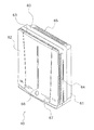
本発明の一実施の形態が採用される空気清浄機40の外観図を図1に示す。
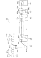
空気清浄機40は、ビルや住宅などの室内空気を清浄し清浄後の空気を室内に送風することにより、室内を快適な環境に保つ。この空気清浄機40は、ケーシング60、送風機構70(図2参照)、制御部50(図4参照)、およびフィルタユニット80(図2参照)を備えている。
<First Embodiment>
[Overall configuration of air purifier]
FIG. 1 shows an external view of an
The
[空気清浄機の構成要素]
(1)ケーシング
ケーシング60は、空気清浄機40の外表面を構成し、送風機構70、制御部50、およびフィルタユニット80を内包する。ケーシング60は、本体部61および正面パネル62を有している。
[Components of the air cleaner]
(1) Casing The
A.本体部
本体部61は、上面吸い込み口63、側面吸い込み口64、および吹き出し口65を有している。上面吸い込み口63および側面吸い込み口64は、空気清浄機40内において室内空気を清浄するために、室内空気を空気清浄機40内に吸い込むための略矩形の開口である。上面吸い込み口63は、吹き出し口65が設けられる面と同じ本体部61上面の正面側端部に設けられる。側面吸い込み口64は、本体部61の側面に左右それぞれ設けられる一対の開口である。吹き出し口65は、本体部61上面の背面側端部に設けられる。吹き出し口65は、清浄後の空気を空気清浄機40から室内に向かって吹き出すための開口である。
A. Main Body The
B.正面パネル
正面パネル62は、本体部61の前方に設けられ、本体部61の内部に設置されるフィルタユニット80を覆っている。正面パネル62は、正面吸い込み口66および表示パネル開口67を有している。正面吸い込み口66は、正面パネル62の略中央部に設けられる室内空気を空気清浄機40内に吸い込むための略矩形の開口である。表示パネル開口67は、後述する表示パネル56がケーシング60外部から目視できるように設けられている。
B. Front Panel The
(2)送風機構
送風機構70は、各吸い込み口(上面吸い込み口63、側面吸い込み口64および正面吸い込み口66)から室内空気を吸い込み、吹き出し口65から清浄後の空気を吹き出す。この送風機構70は、ケーシング60の内方に設けられ、各吸い込み口63,64,66から吸い込んだ室内空気がフィルタユニット80を通過するように構成されている。また、送風機構70は、図2に示されるように、ファンモータ71および送風ファン72を備えている。この送風ファン72は、ファンモータ71によって回転駆動される。ファンモータ71としては、インバータ回路により周波数制御されるインバータモータが採用される。送風ファン72としては、遠心ファンが採用される。
(2) Blower Mechanism The
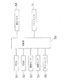
(3)制御部
空気清浄機40は、さらに、マイクロプロセッサで構成される制御部50を備えている。図4に示されるように、制御部50には、制御プログラムや各種パラメータが格納されるROM51、処理中の変数などを一時的に格納するRAM52などが接続されている。
また、制御部50には、温度センサ53、湿度センサ54、およびダストセンサ55などの各種センサ類が接続されており、各センサの検出信号が入力される。ダストセンサ55は、導入される空気中に光を照射し、空気中に含まれる煙、ホコリ、花粉、その他の粒子によって乱射されて受光素子に到達した光量を検出して、粉塵などの粒子濃度を測定することができる。
(3) Control part The
In addition, various sensors such as a
さらに、制御部50には、表示パネル56が接続されている。表示パネル56は、運転モード、各種センサによるモニタ情報、タイマ情報、メンテナンス情報などを表示し、使用者などが外部から表示パネル開口67を介して目視できるようになっている。また、この表示パネル56は、液晶表示パネル・LED・その他の表示素子またはこれらの組み合わせで構成することが可能である。
Further, a
さらに、制御部50は、ファンモータ71に接続されており、使用者の操作や各種センサの検出結果などに応じて、これらの装置の稼働を制御することができる。
(4)フィルタユニット
フィルタユニット80は、ケーシング60の内部に設けられ、各吸い込み口63,64,66から吸い込んだ室内空気に含まれる微粒子を除去する。図2に示されるように、フィルタユニット80は、プレフィルタ81、放電部82、光触媒フィルタ83、およびプラズマ触媒フィルタ84を有している。フィルタユニット80は、各吸い込み口63,64,66から吸い込んだ室内空気がプレフィルタ81、放電部82、光触媒フィルタ83、プラズマ触媒フィルタ84の順にフィルタユニット80内を通過するように構成されている。
Furthermore, the
(4) Filter unit The
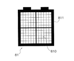
A.プレフィルタ
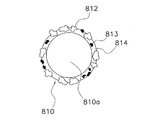
プレフィルタ81は、送風機構70によりケーシング60内に吸い込まれる空気から比較的大きな塵埃などを除去するためのフィルタである。プレフィルタ81は、ネット部810と、フレーム811とを有している(図5参照)。ネット部810は、ポリプロピレン(以下、PPという)製の糸状の樹脂網であって、ケーシング60内に吸い込まれる空気に含まれる比較的大きな塵埃などが付着する。また、ネット部810を構成する繊維は、図6に示されるように、PPによって構成される芯810aと同じくPPによって構成される被覆層814とからなる。被覆層814には、可視光線型の光触媒812とカテキン813とが空気側に露出するように担持されている。可視光線型の光触媒812は、可視光線により光触媒作用が活性化される酸化チタンなどを含んでおり、ネット部810に付着する塵埃などに含まれるカビ菌や細菌などの菌やウィルスを除去する。カテキンは、ポリフェノールの一種であって、エピカテキン、エピガロカテキン、エピカテキンガレート、エピガロカテキンガレートなどの総称である。このカテキンは、ネット部810に付着する塵埃などに含まれるカビ菌や細菌などの菌の繁殖を抑制したりウィルスを不活化したりする。
A. Prefilter The
B.放電部
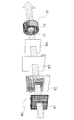
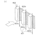
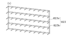
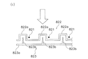
放電部82は、図3(a)、図3(b)、および図3(c)に示されるように、主に、対向電極822、イオン化線821、およびストリーマ放電電極823から構成される。対向電極822は、方形波形状の断面を有する金属板であって、実質的に電極として機能する実電極部822aと複数のスリット部822bとから成る。なお、スリット部822b、空気を後方側に流す役割を果たす。イオン化線821は、対向電極822の空気流れ方向上流側に配置される。なお、このとき、イオン化線821は、実電極部822a間に1つずつ配置される。また、このイオン化線821は、微小径のタングステン線材などによって形成され、放電電極として用いられる。ストリーマ放電電極823は、電極棒823aと針電極823bとから成る。針電極823bは、電極棒823aにほぼ直交するように固定される。そして、このストリーマ放電電極823は、図3(c)に示されるように、対向電極822の空気流れ方向下流側に配置される。なお、このとき、ストリーマ放電電極823は、針電極823bが対向電極822の実電極部822aと対向するように配置される。
B. As shown in FIG. 3A, FIG. 3B, and FIG. 3C, the
なお、これらの電極821,822,823のうち、対向電極822とイオン化線821とは、プレフィルタ81を通過した空気中に浮遊している比較的小さな塵埃を耐電させる役割を担う。一方、対向電極822とストリーマ放電電極823とは、後述するチタンアパタイト担持フィルタ831に供給する活性種を生成する役割を担う。以下、それぞれの電極の組合せについて詳述する。
Of these
(対向電極とイオン化線)
この放電部82において、イオン化線821と実電極部822aとの間に高電圧が印加されると、両電極821,822間に放電が生じる。この結果、両電極821,822間を通過する塵埃などがプラス電荷に帯電される。そして、帯電された塵埃は、スリット部822bを介して後方に供給され、後述する静電フィルタ830によって静電吸着される。また、この際、塵埃に含まれるウィルスや菌なども帯電されるため、後述するチタンアパタイトへのウィルスや菌の吸着効率が高まる。
(Counter electrode and ionization wire)
In the
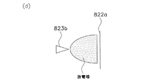
(対向電極とストリーマ放電電極)
この放電部82において、ストリーマ放電電極823と対向電極822との間に直流、交流、またはパルスの放電電圧が印加されると、両電極822,823間に図3(d)に示されるようなストリーマ放電が生じる。このようにして、ストリーマ放電が生じると、放電場に低温プラズマが生成する。そして、この低温プラズマにより、高速電子、イオン、オゾン、ヒドロキシラジカルなどのラジカル種や、その他の励起分子(励起酸素分子、励起窒素分子、励起水分子)などが生成される。そして、これらの活性種は、空気流れに乗ってチタンアパタイト担持フィルタ831に供給される。
(Counter electrode and streamer discharge electrode)
In this
なお、これらの活性種は、非常にエネルギーレベルが高く、チタンアパタイト担持フィルタ831に到達する前であっても、空気に含まれるアンモニア類や、アルデヒド類、窒素酸化物など小さな有機分子を分解・消臭する能力を有する。
C.光触媒フィルタ
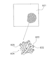
光触媒フィルタ83の断面図の一部を図7に示す。光触媒フィルタ83は、複数回分の長さを巻き込んだロール状とされており、使用中の面が汚れた場合に引き出して汚れた部分をカットするような構成となっている。この光触媒フィルタ83は、静電フィルタ830およびチタンアパタイト担持フィルタ831を張り合わせて形成されている。なお、この光触媒フィルタ83は、静電フィルタ830が送風機構70による空気流れの上流側に、チタンアパタイト担持フィルタ831が空気流れの下流側に面するように配置される。静電フィルタ830は、放電部82で帯電させられた塵埃などを吸着する。チタンアパタイト担持フィルタ831には、静電フィルタ830を通過する塵埃などが付着する。なお、このチタンアパタイト担持フィルタ831は、図8および図9に示されるように、チタンアパタイト粒子835を担持させたPPの繊維834から形成されている。なお、この繊維834は、上記と同様に、芯832と被覆層833とを有し、被覆層833にチタンアパタイト粒子835を担持している。なお、チタンアパタイトとは、カルシウムヒドロキシアパタイトの一部のカルシウム原子がイオン交換などの手法によってチタン原子に置換されたアパタイトである。このチタンアパタイトは、塵埃などに含まれるウィルスやカビ菌、細菌などを特異的に吸着する性質を有する。そして、このチタンアパタイトは、放電部82から供給される活性種により光触媒機能が活性化され、ウィルスやカビ菌、細菌などを不活化または死滅させる。
These active species have a very high energy level, and even before reaching the titanium apatite-carrying
C. Photocatalyst filter A part of a cross-sectional view of the
D.プラズマ触媒フィルタ
プラズマ触媒フィルタ84には、チタンアパタイト担持フィルタ831と同様に、アナターゼ型の二酸化チタンを担持させたPPの繊維から形成されている。プラズマ触媒フィルタ84では、光触媒フィルタ83に吸着されなかった空気中のウィルスや菌などを吸着する。このプラズマ触媒フィルタ84では、吸着された菌やウィルスなどが活性種により活性化された二酸化チタンによって死滅あるいは不活化される。
D. Plasma Catalyst Filter The
[フィルタを形成する繊維の製造装置および製造方法]
上記フィルタ81,83,84を形成する繊維を製造するための溶融紡糸装置90を図10に示す。この溶融防止装置90は、図10に示されるように、主に、第1乾燥装置91a、第2乾燥装置91b、第1吐出装置92a、第2吐出装置92b、射出ノズル93、冷却装置94、繰出装置95、引取装置96、トンネルヒータ97、熱処理装置98、および巻取装置99から構成される。
[Manufacturing apparatus and manufacturing method of fiber forming filter]
FIG. 10 shows a
第1乾燥装置91aには、高融点のポリプロピレン樹脂のペレットが供給される。そして、この第1乾燥装置91aでは、そのペレットが、水分含有率が一定値以下になるまで加熱乾燥される。一方、第2乾燥装置91bには、あらかじめチタンアパタイト粒子835(図9参照)が分散された低融点のポリプロピレン樹脂のペレットが供給される。そして、この第2乾燥装置91bでは、そのペレットが、水分含有率が一定値以下になるまで加熱乾燥される。
High melting point polypropylene resin pellets are supplied to the
第1吐出装置92aには、第1乾燥装置91aにおいて十分に乾燥されたペレットが供給される。第1吐出装置92aは、主に、ヒータ(図示せず)、スクリュー921、およびシリンダ922から構成される。この第1吐出装置92aでは、ヒータによってペレットが融解され、融解されたポリプロピレン(以下、融解PPという)がスクリュー921によりシリンダ922内を射出ノズル93側に向かって移動する。一方、第2吐出装置92bには、第2乾燥装置91bにおいて十分に乾燥されたペレットが供給される。第2吐出装置92bは、第1吐出装置92aと同様に、主に、ヒータ(図示せず)、スクリュー921、およびシリンダ922から構成される。この第2吐出装置92bでは、ヒータによってペレットが融解され、融解されたチタンアパタイト含有ポリプロピレン(以下、TA含有融解PPという)がスクリュー921によりシリンダ922内を射出ノズル93側に向かって移動する。
Pellets sufficiently dried in the
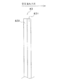
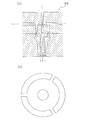
射出ノズル93には、第1吐出装置92aおよび第2吐出装置92bから供給される融解PPおよびTA含有融解PPが供給される。射出ノズル93は、図11(a)に示されるような側断面構造および図11(b)に示されるような形状の吐出口を有する。この射出ノズル93において、融解PPは、第1経路(図11(a)の実線矢印参照)を流れる。一方、TA含有融解PPは、第2経路(図11(a)の破線矢印参照)を流れる。そして、融解PPとTA含有融解PPとは、この射出ノズル93から排出された後に、TA含有融解PPが融解PPを覆うようなかたちで一体化されて(以下、このようにして一体化された融解PPとTA含有融解PPとを複合融解物という)、冷却装置94に送られる。
The
冷却装置94は、複合融解物を、冷却液を利用して冷却・固化し、繊維化する(以下、このようにしてできた繊維を複合繊維という)。そして、複合繊維は、冷却液のタンク内に設置されるディップローラ94aおよび排出ローラ94bを介して、繰出装置95に送られる。
繰出装置95は、繰出ローラ95aを備えており、一定速度で複合繊維をトンネルヒータ97に繰り出す。一方、引取装置96は、引取ローラ96aを備えており、トンネルヒータ97から出てくる複合繊維を、繰出装置95の繰り出し速度よりも速い速度で引き取る。この結果、複合繊維は、繰出装置95と引取装置96との間で、加熱延伸されることになる。この加熱延伸時には、複合繊維の外層(チタンアパタイト粒子835を含有するポリプロピレン樹脂の層)が薄膜化し、内包されているチタンアパタイト粒子835の一部がその表面に露出する(以下、この状態にある繊維をチタンアパタイト露出繊維834(図9参照)という)。チタンアパタイト露出繊維834は、その後、熱処理装置98に導かれる。熱処理装置98はヒータ(図示せず)を有し、その内部は所定の温度になるように加熱されている。この熱処理装置98では、チタンアパタイト露出繊維834は、ガイドローラ98aに沿って移動されながら熱処理される。この熱処理によって、チタンアパタイト露出繊維834の芯832の結晶化が進み、その強度が一定値以上に保たれる。そして、熱処理装置98から出たチタンアパタイト露出繊維834は、巻取装置99の巻取ローラ99aによって巻き取られる。
The
The
以上の工程を経て製造されたチタンアパタイト露出繊維834は、図9に示されるような形状を呈することになる。
[フィルタの製造方法]
上記フィルタ81,83,84は、上記のチタンアパタイト露出繊維834を織ることなく熱融着させることによって不織布として製造される。
The titanium apatite exposed
[Filter manufacturing method]
The
[本空気清浄機の特徴]
(1)
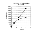
第1実施形態に係る空気清浄機40では、光触媒フィルタ83を形成する繊維にチタンアパタイト粒子835が担持される。チタンアパタイトは、図12に示されるように、アセトアルデヒドに対して、従来のアナターゼ型の二酸化チタンよりも優れた分解処理性能を発揮する。なお、図12のグラフにおいて、縦軸は二酸化炭素濃度であり、横軸は時間である。つまり、アセトアルデヒドの分解により生じる二酸化炭素の濃度を測定することにより間接的に分解処理性能を測定していることになる。なお、この測定は、チタンアパタイトの表面積と二酸化チタンの表面積とを一致させて行われている。また、図12のグラフから明らかなように、チタンアパタイトの方が二酸化チタンよりも高い分解処理性能を示す。また、チタンアパタイトは3時間が経過しても一定の反応速度でアセトアルデヒドを分解し続けるのに対し、二酸化チタンは3時間を経過するとその分解能力がほぼ飽和し、両者の分解処理性能の差が著しくなる。このため、この空気清浄機40は、菌やウィルスなどに対して、従来のアナターゼ型の二酸化チタンを利用した空気清浄機よりも優れた分解処理能力を実現することができる。
[Features of this air cleaner]
(1)
In the
また、図13に示されるように、アナターゼ型の二酸化チタンが菌やウィルスだけでなく自身を担持する基材(ウレタン樹脂)をも浸食するのに対し、チタンアパタイトは、基材をほとんど浸食しない。このため、チタンアパタイトは、従来のアナターゼ型の二酸化チタンを有機物に担持する際に使用されていた高価な特殊バインダを使用する必要がない。したがって、このチタンアパタイトを利用すれば、菌やウィルスなどに対して、優れた分解処理能力を提供することができるだけでなく、安価に光触媒機能を有する繊維を製造することができる。 As shown in FIG. 13, anatase-type titanium dioxide erodes not only bacteria and viruses but also a base material (urethane resin) supporting itself, whereas titanium apatite hardly erodes the base material. . For this reason, titanium apatite does not require the use of an expensive special binder that has been used when organic anatase-type titanium dioxide is supported on an organic substance. Therefore, if this titanium apatite is used, it is possible not only to provide an excellent decomposition treatment ability against bacteria and viruses, but also to produce a fiber having a photocatalytic function at low cost.
(2)
第1実施形態に係る空気清浄機40では、光触媒フィルタ83を構成する繊維834が芯832と被覆層833とからなり、その被覆層833にはチタンアパタイト粒子835が空気側に露出するように担持されている。一般に、樹脂に粒子フィラーなどが充填されると、その樹脂が脆くなる傾向が強い。しかし、この繊維834は、芯832を有しているため、そのおそれがほとんどない。また、チタンアパタイト粒子835が空気側に露出していることによりチタンアパタイトがその光触媒機能を十分に発揮することができる。
(2)
In the
[変形例]
(A)
第1実施形態に係る空気清浄機40では、チタンアパタイトの光触媒機能が、活性種により活性化されたが、これに代えて、紫外線ランプなどを採用することによりチタンアパタイトの光触媒機能を活性化させてもよい。
[Modification]
(A)
In the
(B)
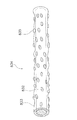
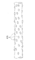
第1実施形態に係る空気清浄機40では、光触媒フィルタ83を形成する繊維として芯832を有する繊維834が採用されたが、図14に示されるような一部のチタンアパタイト粒子835が内部にほぼ均一に分散された繊維が採用されてもよい。なお、このような場合であっても一部のチタンアパタイトは繊維834の表面に露出している。
(B)
In the
(C)
第1実施形態では、本発明を空気清浄機40に適用しているが、図15に示すような冷暖房を行う空気調和機200に本発明を適用してもよい。
この空気調和機200は、調和された空気を室内に供給するための装置であって、室内の壁面などに取り付けられる室内機201と、室外に設置される室外機202とを備えている。室内機201には、室内の空気を空気調和機200内に取り込むための吸い込み口205が設けられており、この吸い込み口205の内側にフィルタユニット(図示せず)が装備される。このフィルタユニットに対して本発明を適用した場合にも、フィルタユニットに付着および吸着されるウィルスやカビ菌、細菌などが除去されるため、悪臭の発生や空気の汚染が起こることを抑えられる。
(C)
In 1st Embodiment, although this invention is applied to the
The
(D)
第1実施形態に係る空気清浄機40では、プラズマ触媒フィルタ84に、チタンアパタイト担持フィルタ831と同様に、アナターゼ型の二酸化チタンを担持させたPPの繊維から形成されていたが、これに代えて、二酸化チタンをプラズマフィルタ84の片面または両面に塗布してもよい。
(D)
In the
<第2実施形態>
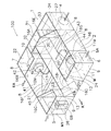
本発明の一実施形態に係る全熱交換ユニットの内部構造を示す斜視図を図16に、上面図を図17に、側面図を図18に、分解斜視図を図19に示す。なお、この全熱交換ユニット100は、図16に示されるように、屋外からの給気SA(実線白抜矢印)と室内からの排気EA(ハッチング付き矢印)との間で熱交換エレメント12を介して熱交換させつつ換気するための装置である。
Second Embodiment
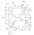
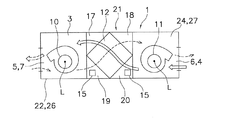
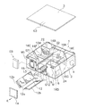
FIG. 16 is a perspective view showing the internal structure of the total heat exchange unit according to the embodiment of the present invention, FIG. 17 is a top view, FIG. 18 is a side view, and FIG. 19 is an exploded perspective view. As shown in FIG. 16, the total
[全熱交換ユニットの構成]
本全熱交換ユニット100は、図16、図17、図18、および図19に示されるように、主に、ケーシング1、熱交換エレメント12、エアフィルタ12b、ファン10,11、ダンパ34、および電装品ボックスEBから構成される。
[全熱交換ユニットの構成要素]
(1)ケーシング
ケーシング1は、図16および図19に示されるように、箱体2と、この箱体2の上面を覆う蓋体3とから構成される。そして、このケーシング1には、熱交換エレメント室21、排気用ファンモータ収容室41、排気用ファン収容室22、給気用ファンモータ収容室43、給気用ファン収容室24、給気連通室45、排気連通室46、室外側吸込室26、室内側吸込室27、およびバイパス室31が設けられる。以下、上述した各室について詳述する。
[Configuration of total heat exchange unit]
As shown in FIGS. 16, 17, 18, and 19, the total
[Components of the total heat exchange unit]
(1) Casing The
A.熱交換エレメント室
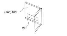
熱交換エレメント室21は、図16および図18に示されるように、直方体形状の空間であって、熱交換エレメント12を収容する。なお、この熱交換エレメント室21は、箱体2の底板、仕切板16A〜16E(図16、図20、および図21参照)、および蓋体3などによって仕切られて形成される。また、箱体2の底板、仕切板16A〜16E、および蓋体3には、それぞれガイド部G1,G2,G3が取り付けられる。箱体2の底板に取り付けられるガイド部G1は、第1ガイド部G11と第2ガイド部G12とを有する。第1ガイド部G11は、熱交換エレメント12の挿脱時に熱交換エレメント12の下部の稜線を案内する。一方、第2ガイド部G12は、第1ガイド部G11を挟んで対をなしており、一対のエアフィルタ12bの端縁をそれぞれ案内する。仕切板16A〜16Eに取り付けられるガイド部G2は、第1ガイド部G21と第2ガイド部G22とを有する。第1ガイド部G21は、熱交換エレメント12の挿脱時に熱交換エレメント12の側部の稜線を案内する。一方、第2ガイド部G22は、エアフィルタ12bの端縁を案内する。蓋体3に取り付けられるガイド部G3は、熱交換エレメント12の挿脱時に熱交換エレメント12の上部の稜線を案内する。
A. Heat Exchange Element Chamber As shown in FIGS. 16 and 18, the heat
なお、この熱交換エレメント室21に熱交換エレメント12が収容されると、その周囲に略三角柱形状の4つの空間17,18,19,20が生成する。以下、図16および図18中、図番17により示される空間を第1空間、図番18により示される空間を第2空間、図番19により示される空間を第3空間、図番20により空間を第4空間という。
B.排気用ファン収容室
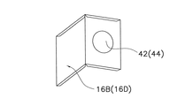
排気用ファン収容室22は、図16および図19に示されるように、排気用ファン10を収容する。また、この排気用ファン収容室22は、図16に示されるように、仕切板16Bに形成された開口42を介して排気用ファンモータ収容室41に連通する。また、この排気用ファン収容室22は、図16に示されるように、側壁に排気用の室外側吹出口7を有している。
In addition, when the
B. Exhaust Fan Housing Chamber The exhaust
C.排気用ファンモータ収容室
排気用ファンモータ収容室41は、図16および図19に示されるように、排気用ファンモータ10Mを収容する。また、この排気用ファンモータ収容室41は、図16に示されるように、蓋体3と熱交換エレメント12の一の稜線とで仕切られる開口23を介して第1空間17に連通する。
C. Exhaust Fan Motor Housing Chamber The exhaust fan
D.給気用ファン収容室
給気用ファン収容室24は、図16および図19に示されるように、給気用ファン11を収容する。また、給気用ファン収容室24は、図16に示されるように、仕切板16Dに形成された開口44を介して給気用ファンモータ収容室43に連通する。また、この給気用ファン収容室24は、図16に示されるように、側壁に給気用の室内側吹出口6を有している。
D. Air supply fan storage chamber The air supply
E.給気用ファンモータ収容室
給気用ファンモータ収容室43は、図16および図19に示されるように、給気用ファンモータ11Mを収容する。また、この給気用ファンモータ収容室43は、蓋体3と熱交換エレメント12の一の稜線とで仕切られる開口25を介して第2空間18に連通する。
F.室外側吸込室
室外側吸込室26は、図16に示されるように、側壁に給気用の室外側吸込口5を有している。また、この室外側吸込室26は、図16および図20に示されるように、仕切板16Cの開口29を介して給気連通室45に連通する。
E. Air supply fan motor storage chamber The air supply fan
F. As shown in FIG. 16, the
G.室内側吸込室
室内側吸込室27は、図16に示されるように、側壁に排気用の室内側吸込口4を有している。また、この室内側吸込室27は、図16に示されるように、仕切板16Eの開口30を介して排気連通室46に連通する。
H.給気連通室
給気連通室45は、仕切板16Fによって仕切られており、排気用ファンモータ収容室41の下方に位置する。また、この給気連通室45は、図16に示されるように、第3空間19に連通する。
G. Indoor Side Suction Chamber As shown in FIG. 16, the indoor
H. Air supply communication chamber The air
I.排気連通室
排気連通室46は、仕切板16Gによって仕切られており、給気用ファンモータ収容室43の下方に位置する。また、この排気連通室46は、図16に示されるように、第4空間20に連通する。
J.バイパス室
バイパス室31は、熱交換エレメント室21の反抜取り方向側に位置している。そして、このバイパス室31は、開口32を介して第1空間17に連通する。また、このバイパス室31は、開口33を介して室内側吸込室27に連通する。この結果、排気用ファン収容室22と室内側吸込室27とは、排気用ファンモータ収容室41、第1空間17、およびバイパス室31を介して連通することとなる。
I. Exhaust communication chamber The
J. et al. Bypass chamber The
(2)熱交換エレメント
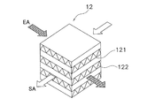
熱交換エレメント12は、図16および図17に示されるように、略直方体の形状をしており、排気通路8と給気通路9との交差部に設けられている。この熱交換エレメント12は、図22に示されるように、プリーツ状の特殊クラフト紙(以下、スペーサ紙という)122と平膜状の特殊クラフト紙(以下、仕切紙という)121とを交互に方向を変えながら積層した構造を有している。この熱交換エレメント12がこのような構造をとっているため、この熱交換エレメント12では、排気EAの流路と給気SAの流路とが一段ごとに交互に配置されるかたちになる。なお、この熱交換エレメント12では、給気SAおよび排気EAの顕熱および潜熱は、この仕切紙121を介して交換される。なお、このスペーサ紙122および仕切紙121には、第1実施形態の光触媒フィルタと同様に、チタンアパタイト粒子が担持されている。このチタンアパタイトは、カルシウムヒドロキシアパタイトのカルシウム原子の一部がイオン交換などの手法によってチタン原子に置換されたアパタイトであって、優れた有機物(特に菌やウィルスなど)の吸着性能を示すとともに光半導体触媒としての性質をも示し、エネルギーレベルの高い波長の光(例えば、紫外線など)や活性種などが照射あるいは供給されると、光半導体触媒として代表的なアナターゼ型の二酸化チタンよりも優れた汚物分解処理性能を示す。
(2) Heat Exchange Element As shown in FIGS. 16 and 17, the
なお、この熱交換エレメント12の端面には取り出しのための把手12aが設けられており、図19に示されるように蓋14を取り外せば、ケーシング1のメンテナンス面Mに開口される挿脱用の開口13から、その長辺に沿って長手方向に挿脱できるようになっている。
(3)エアフィルタ
エアフィルタ12bは、図19に示されるように、熱交換エレメント12の第3空間19に接する面と第4空間20に接する面とを覆うように熱交換エレメント12に取り付けられる。このエアフィルタ12bは、ポリテトラフルオロエチレン繊維から成る不織布である。なお、このエアフィルタ12bは、比較的大きな塵埃を主に捕集するためのフィルタであって、菌やウィルスなどの微少な生体粒子を捕捉することはできない。
Note that a
(3) Air Filter The
(4)ストリーマ放電器
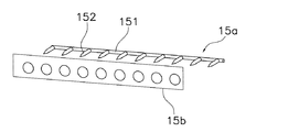
ストリーマ放電器15は、第3空間19および第4空間20にそれぞれ設けられており、高速電子、イオン、オゾン、ヒドロキシラジカルなどのラジカルや、その他の励起分子(励起酸素分子、励起窒素分子、励起水分子)などの活性種を熱交換エレメント12内部に供給することによって、熱交換エレメント12内部に担持されているチタンアパタイトの光触媒機能を活性化させる。このストリーマ放電器15は、放電電極15aと対向電極15bとから構成される。放電電極15aは、図23に示されるように、電極棒151と複数の針電極152とから構成される。なお、針電極152は、電極棒151にほぼ直交するように固定される。対向電極15bは、板状の電極であって、その面直角方向に空気が通過する複数の開口を有している。そして、放電電極15aの電極棒151と対向電極15bとは、ほぼ平行に配置される。その結果、放電電極15aの針電極152は、対向電極15bとほぼ直角をなす。また、放電電極15aと対向電極15bとは、直流、交流、またはパルスの高圧電源(図示せず)に接続されている。そして、放電電極15aと対向電極15bとに放電電圧が印加されると、放電電極15aの針電極152と対向電極との間でストリーマ放電が生じる。このようにして、ストリーマ放電が生じると、放電場に低温プラズマが生成する。そして、この低温プラズマにより、高速電子、イオン、オゾン、ヒドロキシラジカルなどのラジカルや、その他の励起分子(励起酸素分子、励起窒素分子、励起水分子)などが生成される。なお、これらの活性種は、空気流れに乗って対向電極15bの開口を通って熱交換エレメント12内部に供給されることとなる。
(4) Streamer discharger The
なお、このストリーマ放電器15は、後述する熱交換エレメント清浄モードにおいてのみ通電される。
(5)ファン
排気用ファン10および給気用ファン11は、図17および図18に示されるように、それぞれシロッコファン(ロータ)からなり、発泡樹脂(例えば発泡スチロール)製の渦巻き状をしたファンケーシング(図示せず)内に収容されている。なお、各ファン10,11の回転軸線Lは、熱交換エレメント12の抜取り方向Kと平行である。
The
(5) Fan As shown in FIGS. 17 and 18, the
(6)ダンパ
ダンパ34は、室内側吸込室27内に配置されている。このダンパ34は、例えば電動モータ(図示せず)などによって回動し、開口30と開口33とのいずれか一方を開放し他方を閉塞する。
(7)電装品ボックス
電装品ボックスEBは、メンテナンス面Mの排気用ファン10と対向する部分M1に配置されている。この電装品ボックスEBには、電装品として、図示しない制御基板などが収容されている。なお、この制御基板は、図示しないワイヤードリモコンに通信接続されており、このワイヤードリモコンから送信されてくる信号に基づいてファン10,11およびダンパ34の動作を制御する。
(6) Damper The
(7) Electrical component box The electrical component box EB is disposed in a portion M1 of the maintenance surface M facing the
[給排気の流れ]
この全熱交換ユニット100には、全熱交換換気モード、普通換気モード、および熱交換エレメント清浄モードの3つの運転モードが設けられている。以下、それぞれの運転モードについて詳述する。
(1)全熱交換換気モード
この全熱交換ユニット100では、熱交換エレメント12を用いた全熱交換換気を行う場合、ダンパ34によって開口30が開放される。なお、上述したように、このとき、開口33は閉塞される。そして、この状態で各ファン10,11が運転されると、室内空気がダクトを介して室内側吸込口4から室内側吸込室27に吸い込まれ、開口30→排気連通室46→第4空間20→エアフィルタ12b→熱交換エレメント12→第1空間17→開口23→排気用ファンモータ収容室41→排気用ファン収容室22に至る排気通路8を通り、室外側吹出口7から吹き出されダクトを介して室外に排出されると同時に、室外空気がダクトを介して室外側吸込口5から室外側吸込室26に吸い込まれ、給気連通室45→第3空間19→エアフィルタ12b→熱交換エレメント12→第2空間18→開口25→給気用ファンモータ収容室43→開口44→給気用ファン収容室24に至る給気通路9を通り、室内側吹出口6から吹き出されダクトを介して室内に給気される。
[Flow of supply and exhaust]
The total
(1) Total heat exchange ventilation mode In this total
(2)通常換気モード
春秋などの冷暖房を必要としない中間期には、熱交換を行わない通常換気が行われる。
この全熱交換ユニット100では、通常換気が行われる場合、ダンパ34によって開口33が開放される。なお、上述したように、このとき、開口30は閉塞される。そして、この状態で各ファン10,11が運転されると、室内空気がダクトを介して室内側吸込口4から室内側吸込室27に吸い込まれ、開口33→バイパス室31→開口32→第1空間17→開口23→排気用ファンモータ収容室41→排気用ファン収容室22に至るバイパス通風路を通り、室外側吹出口7から吹き出され、ダクトを介して室外に排出されると同時に、室外空気がダクトを介して室外側吸込口5から室外側吸込室26に吸い込まれ、給気連通室45→第3空間19→エアフィルタ12b→熱交換エレメント12→第2空間18→開口25→給気用ファンモータ収容室43→開口44→給気用ファン収容室24に至る給気通路9を通り、室内側吹出口6から吹き出されダクトを介して室内に給気される(給気の流れは全熱交換換気の場合と同じである。)。
(2) Normal ventilation mode Normal ventilation without heat exchange is performed in the middle period that does not require air conditioning such as spring and autumn.
In the total
(3)熱交換エレメント清浄モード
エアフィルタ清浄モードでは、ファン10,11の回転数が送風量を極力抑えた状態になるように制御されると同時に、ストリーマ放電器15が、通電される。
[全熱交換ユニットの特徴]
(1)
第2実施形態に係る全熱交換ユニット100では、熱交換エレメント12を形成する繊維にチタンアパタイトが担持される。このため、この全熱交換ユニット100は、菌やウィルスなどに対して、従来のアナターゼ型の二酸化チタンを利用した熱交換ユニットよりも優れた分解処理能力を実現することができる。
(3) Heat Exchange Element Cleaning Mode In the air filter cleaning mode, the
[Characteristics of total heat exchange unit]
(1)
In the total
また、チタンアパタイトは、従来のアナターゼ型の二酸化チタンを有機物に担持する際に使用されていた高価な特殊バインダを使用する必要がない。したがって、このチタンアパタイトを利用すれば、菌やウィルスなどに対して、優れた分解処理能力を提供することができるだけでなく、安価に光触媒機能を有する繊維を製造することができる。
(2)
第1実施形態に係る全熱交換ユニット100では、熱交換エレメント12を構成する繊維が芯と被覆層とからなり、その被覆層にはチタンアパタイトが空気側に露出するように担持されている。一般に、樹脂に粒子フィラーなどが充填されると、その樹脂が脆くなる傾向が強い。しかし、この繊維は、芯を有しているため、そのおそれがほとんどない。また、チタンアパタイトが空気側に露出していることによりチタンアパタイトがその光触媒機能を十分に発揮することができる。
In addition, titanium apatite does not require the use of an expensive special binder that has been used for supporting conventional anatase-type titanium dioxide on an organic substance. Therefore, if this titanium apatite is used, it is possible not only to provide an excellent decomposition treatment ability against bacteria and viruses, but also to produce a fiber having a photocatalytic function at low cost.
(2)
In the total
[変形例]
第1実施形態に係る全熱交換ユニット100では、熱交換エレメント12を構成する繊維が芯と被覆層とからなり、その被覆層にはチタンアパタイトが空気側に露出するように担持されていたが、これに加えて、エアフィルタ12bを構成する繊維も同様の形態でチタンアパタイトを担持してもよい。
[Modification]
In the total
本発明に係る光半導体触媒担持繊維は、従来の光半導体触媒担持繊維よりも安価に製造することができ、空気の清浄化のみならず水などの液体などの清浄化にも適用できる。 The photo-semiconductor catalyst-supporting fiber according to the present invention can be manufactured at a lower cost than conventional photo-semiconductor catalyst-supporting fibers, and can be applied not only to cleaning air but also to cleaning liquids such as water.
12 熱交換エレメント
40 空気清浄機(空気調和装置)
83 光触媒フィルタ(エアフィルタ)
100 熱交換ユニット
832 芯(芯部)
833 被覆層(被覆部)
834 PP繊維(光半導体触媒担持繊維)
835 チタンアパタイト粒子(光触媒機能を有するアパタイト)
12
83 Photocatalytic filter (air filter)
100
833 Coating layer (coating part)
834 PP fiber (fiber supporting optical semiconductor catalyst)
835 Titanium apatite particles (apatite with photocatalytic function)
Claims (6)
前記芯部(832)を覆う被覆部(833)と、
前記被覆部(833)の空気側に露出するように前記被覆部(833)に担持される光触媒機能を有するアパタイト(835)と、
を備える、光半導体触媒担持繊維(834)。 A core (832);
A covering portion (833) covering the core portion (832);
An apatite (835) having a photocatalytic function carried on the covering portion (833) so as to be exposed to the air side of the covering portion (833);
An optical semiconductor catalyst-carrying fiber (834).
Priority Applications (2)
| Application Number | Priority Date | Filing Date | Title |
|---|---|---|---|
| JP2004120840A JP2005296900A (en) | 2004-04-15 | 2004-04-15 | Optical semiconductor catalyst-supporting fiber, air filter, air conditioner, heat exchange element, and heat exchange unit |
| CNU2005200118279U CN2841143Y (en) | 2004-04-15 | 2005-04-15 | Semiconductor photocatalyst-carrying fibers, air filters, air conditioners, heat exchange elements, and heat exchange components |
Applications Claiming Priority (1)
| Application Number | Priority Date | Filing Date | Title |
|---|---|---|---|
| JP2004120840A JP2005296900A (en) | 2004-04-15 | 2004-04-15 | Optical semiconductor catalyst-supporting fiber, air filter, air conditioner, heat exchange element, and heat exchange unit |
Publications (1)
| Publication Number | Publication Date |
|---|---|
| JP2005296900A true JP2005296900A (en) | 2005-10-27 |
Family
ID=35329091
Family Applications (1)
| Application Number | Title | Priority Date | Filing Date |
|---|---|---|---|
| JP2004120840A Pending JP2005296900A (en) | 2004-04-15 | 2004-04-15 | Optical semiconductor catalyst-supporting fiber, air filter, air conditioner, heat exchange element, and heat exchange unit |
Country Status (2)
| Country | Link |
|---|---|
| JP (1) | JP2005296900A (en) |
| CN (1) | CN2841143Y (en) |
Cited By (3)
| Publication number | Priority date | Publication date | Assignee | Title |
|---|---|---|---|---|
| JP2007229672A (en) * | 2006-03-03 | 2007-09-13 | Satoo Techno:Kk | Gas reforming method, gas reforming net, gas reforming sheet, gas reforming piping, and fuel cell |
| JP2007262621A (en) * | 2006-03-29 | 2007-10-11 | Fujitsu Ltd | Fiber having photocatalytic activity, fabric using the fiber, and fabric product using the fabric |
| CN107178821A (en) * | 2017-07-18 | 2017-09-19 | 唐山精研实业有限责任公司 | Using low valley power storage heating, sterilization, reduce PM2.5 device |
Citations (6)
| Publication number | Priority date | Publication date | Assignee | Title |
|---|---|---|---|---|
| JPH11342310A (en) * | 1998-03-31 | 1999-12-14 | Mitsubishi Paper Mills Ltd | Functional electret filter, method for producing the same, and air cleaning device |
| JP2000042364A (en) * | 1998-08-03 | 2000-02-15 | Daikin Ind Ltd | Photocatalytic element |
| JP2001302220A (en) * | 2001-03-30 | 2001-10-31 | Fujitsu Ltd | Metal-modified apatite material and method for producing the same |
| JP2003175338A (en) * | 2001-12-12 | 2003-06-24 | Fujitsu Ltd | Method of forming metal-modified apatite film having photocatalytic function and metal-modified apatite coating material |
| JP2003313728A (en) * | 2002-04-25 | 2003-11-06 | Mitsubishi Rayon Co Ltd | Deodorant fiber, method for producing the same, and woven / knitted fabric |
| JP2004052147A (en) * | 2002-07-18 | 2004-02-19 | Izumi Tile Carpet Kk | Deodorant/antimicrobial textile product or deodorant/antimicrobial textile processed product using apatite coating-type photocatalytic titanium oxide |
-
2004
- 2004-04-15 JP JP2004120840A patent/JP2005296900A/en active Pending
-
2005
- 2005-04-15 CN CNU2005200118279U patent/CN2841143Y/en not_active Expired - Lifetime
Patent Citations (6)
| Publication number | Priority date | Publication date | Assignee | Title |
|---|---|---|---|---|
| JPH11342310A (en) * | 1998-03-31 | 1999-12-14 | Mitsubishi Paper Mills Ltd | Functional electret filter, method for producing the same, and air cleaning device |
| JP2000042364A (en) * | 1998-08-03 | 2000-02-15 | Daikin Ind Ltd | Photocatalytic element |
| JP2001302220A (en) * | 2001-03-30 | 2001-10-31 | Fujitsu Ltd | Metal-modified apatite material and method for producing the same |
| JP2003175338A (en) * | 2001-12-12 | 2003-06-24 | Fujitsu Ltd | Method of forming metal-modified apatite film having photocatalytic function and metal-modified apatite coating material |
| JP2003313728A (en) * | 2002-04-25 | 2003-11-06 | Mitsubishi Rayon Co Ltd | Deodorant fiber, method for producing the same, and woven / knitted fabric |
| JP2004052147A (en) * | 2002-07-18 | 2004-02-19 | Izumi Tile Carpet Kk | Deodorant/antimicrobial textile product or deodorant/antimicrobial textile processed product using apatite coating-type photocatalytic titanium oxide |
Cited By (3)
| Publication number | Priority date | Publication date | Assignee | Title |
|---|---|---|---|---|
| JP2007229672A (en) * | 2006-03-03 | 2007-09-13 | Satoo Techno:Kk | Gas reforming method, gas reforming net, gas reforming sheet, gas reforming piping, and fuel cell |
| JP2007262621A (en) * | 2006-03-29 | 2007-10-11 | Fujitsu Ltd | Fiber having photocatalytic activity, fabric using the fiber, and fabric product using the fabric |
| CN107178821A (en) * | 2017-07-18 | 2017-09-19 | 唐山精研实业有限责任公司 | Using low valley power storage heating, sterilization, reduce PM2.5 device |
Also Published As
| Publication number | Publication date |
|---|---|
| CN2841143Y (en) | 2006-11-29 |
Similar Documents
| Publication | Publication Date | Title |
|---|---|---|
| KR100577214B1 (en) | Ventilation combined air cleaner | |
| JP4561710B2 (en) | Deodorizing function regeneration device | |
| JP5218308B2 (en) | Deodorizing function regeneration device | |
| KR20090058446A (en) | Air cleaning and humidification unit | |
| CA2548699A1 (en) | Air quality device | |
| JP2005296901A (en) | Cleaning treatment material, air filter, air conditioner, heat exchange element, and heat exchange unit | |
| KR20170051173A (en) | apparatus and method for both humidification and air cleaning | |
| JP2001248865A (en) | Air-cleaning device with ventilation function | |
| WO2007010972A1 (en) | Air-conditioning equipment | |
| JP2005300111A (en) | Air purification unit, air conditioning apparatus, and air conditioning system | |
| JP2011012822A (en) | Air conditioner | |
| JP2005076906A (en) | Air conditioner | |
| JP2005164069A (en) | Air cleaning system and air cleaning device | |
| TWI507646B (en) | Air cleaner | |
| JP4124218B2 (en) | Heat exchange unit | |
| JP2005296900A (en) | Optical semiconductor catalyst-supporting fiber, air filter, air conditioner, heat exchange element, and heat exchange unit | |
| JP2006017359A (en) | Air cleaner | |
| JP6020805B2 (en) | Air cleaner | |
| JP4830697B2 (en) | Air cleaner | |
| JP4124217B2 (en) | Heat exchange unit | |
| JP2015021629A (en) | Air conditioner | |
| WO2005100873A1 (en) | Heat exchanging unit | |
| JP2011005348A (en) | Dehumidifier | |
| JP3749118B2 (en) | Air purifier | |
| JP2008012060A (en) | Air cleaner |
Legal Events
| Date | Code | Title | Description |
|---|---|---|---|
| A621 | Written request for application examination |
Free format text: JAPANESE INTERMEDIATE CODE: A621 Effective date: 20060223 |
|
| A977 | Report on retrieval |
Free format text: JAPANESE INTERMEDIATE CODE: A971007 Effective date: 20081119 |
|
| A131 | Notification of reasons for refusal |
Free format text: JAPANESE INTERMEDIATE CODE: A131 Effective date: 20081202 |
|
| A521 | Request for written amendment filed |
Free format text: JAPANESE INTERMEDIATE CODE: A523 Effective date: 20090120 |
|
| A131 | Notification of reasons for refusal |
Free format text: JAPANESE INTERMEDIATE CODE: A131 Effective date: 20091027 |
|
| A521 | Request for written amendment filed |
Free format text: JAPANESE INTERMEDIATE CODE: A523 Effective date: 20091218 |
|
| RD02 | Notification of acceptance of power of attorney |
Free format text: JAPANESE INTERMEDIATE CODE: A7422 Effective date: 20091218 |
|
| A02 | Decision of refusal |
Free format text: JAPANESE INTERMEDIATE CODE: A02 Effective date: 20101221 |