JP2005296797A - Coating header, thin film forming apparatus provided with the same, and reverse printing device - Google Patents

Coating header, thin film forming apparatus provided with the same, and reverse printing device Download PDF

Info

Publication number
JP2005296797A
JP2005296797A JP2004116678A JP2004116678A JP2005296797A JP 2005296797 A JP2005296797 A JP 2005296797A JP 2004116678 A JP2004116678 A JP 2004116678A JP 2004116678 A JP2004116678 A JP 2004116678A JP 2005296797 A JP2005296797 A JP 2005296797A
Authority
JP
Japan
Prior art keywords
coating
header
liquid
thin film
coated
Prior art date
Legal status (The legal status is an assumption and is not a legal conclusion. Google has not performed a legal analysis and makes no representation as to the accuracy of the status listed.)
Withdrawn
Application number
JP2004116678A
Other languages
Japanese (ja)
Inventor
Masakazu Aoki
将一 青木
Masahiro Sugihara
正浩 杉原
Masahiro Matsubara
正浩 松原
Current Assignee (The listed assignees may be inaccurate. Google has not performed a legal analysis and makes no representation or warranty as to the accuracy of the list.)
Mitsubishi Heavy Industries Ltd
Original Assignee
Mitsubishi Heavy Industries Ltd
Priority date (The priority date is an assumption and is not a legal conclusion. Google has not performed a legal analysis and makes no representation as to the accuracy of the date listed.)
Filing date
Publication date
Application filed by Mitsubishi Heavy Industries Ltd filed Critical Mitsubishi Heavy Industries Ltd
Priority to JP2004116678A priority Critical patent/JP2005296797A/en
Publication of JP2005296797A publication Critical patent/JP2005296797A/en
Withdrawn legal-status Critical Current

Links

Images

Abstract

<P>PROBLEM TO BE SOLVED: To provide a material liquid coating header for a thin film forming apparatus by which the material liquid is stably applied to a material to be coated with a uniform thickness and a coating rate is improved, and to provide the thin film forming apparatus provided with the coating header, and a reverse printing device. <P>SOLUTION: The coating header for the thin film forming apparatus is used for forming a thin film on a coating surface of the material to be coated by applying the liquid coating liquid on the coating surface. A lip downstream side surface in a lip part of the tip of the coating header for supplying the coating liquid to the material to be coated is worked to be inclined to the coating surface side at an angle ranging from 0° to 20° to the center line of the coating header and the lip part is arranged upward to be adjacent to the coating surface of the material to be coated which is inclined downward at an angle ranging from 20° to 65°. Thus, the material liquid does not interlock to apply the coating liquid (a) with a stable bead shape, thereby preventing the occurrence of problems such as a ring pattern to improve a coating precision and a coating rate. <P>COPYRIGHT: (C)2006,JPO&NCIPI

Description

本発明は、相対的に移動する被塗工材の塗工面に対し液状の材料液を供給することにより移動方向に沿って被塗工材に材料液を塗工する薄膜形成装置の塗工ヘッダ、およびそれを備えた薄膜形成装置と反転印刷装置に関する。   The present invention relates to a coating header of a thin film forming apparatus that applies a material liquid to a coating material along a moving direction by supplying a liquid material liquid to a coating surface of the coating material to be moved relatively. And a thin film forming apparatus and a reverse printing apparatus including the same.

最近、液晶表示装置等が広く普及するようになり、この液晶表示装置のガラス板やそのガラス基板に貼られる保護板等の基材に材料液を塗工して、極薄い薄膜を形成する必要が出てきた。そのような場合に用いられる薄膜形成装置の一般的な例の概要構成図を図12に示し説明する。   Recently, liquid crystal display devices and the like have become widespread, and it is necessary to form a very thin thin film by applying a material solution to a substrate such as a glass plate of the liquid crystal display device or a protective plate attached to the glass substrate. Came out. A schematic configuration diagram of a general example of a thin film forming apparatus used in such a case will be described with reference to FIG.

図12において、100は薄膜形成装置であり、塗工ヘッダ101と、塗工ヘッダ101に材料液(塗工液)aを供給する図示しない材料液供給装置と、塗工ヘッダ移動装置102と、各種基板等の基材(被薄膜形成材)110とが所定位置にセットされる台枠103を有している。また。その上方に位置して、塗工ヘッダ101から供給された材料液aを基材110に転写する薄膜塗工ローラ(被塗工材であるシリンダ状部材)104と、薄膜塗工ローラ104を移動するための図示しないローラ移動装置と、薄膜塗工ローラ104を回転するための図示しないローラ回転駆動装置とを備えて構成されている。   In FIG. 12, 100 is a thin film forming apparatus, a coating header 101, a material liquid supply apparatus (not shown) for supplying a material liquid (coating liquid) a to the coating header 101, a coating header moving apparatus 102, A base frame 103 on which a base material (film forming material) 110 such as various substrates is set at a predetermined position is provided. Also. A thin film coating roller (a cylinder-shaped member that is a material to be coated) 104 that transfers the material liquid a supplied from the coating header 101 to the base material 110 and a thin film coating roller 104 are positioned above it. And a roller rotation device (not shown) for rotating the thin film coating roller 104.

薄膜形成装置100における塗工工程を図12により説明すると、図12(a)に示すように、薄膜塗工ローラ104を、先ずローラ移動装置により塗工ヘッダ101の上方に移動させる。このとき、薄膜塗工ローラ104は回転停止状態とされ、塗工ヘッダ101は薄膜塗工ローラ104と接触しない下降位置とされている。   The coating process in the thin film forming apparatus 100 will be described with reference to FIG. 12. As shown in FIG. 12A, the thin film coating roller 104 is first moved above the coating header 101 by the roller moving device. At this time, the thin film coating roller 104 is in a rotation stopped state, and the coating header 101 is in a lowered position where it does not contact the thin film coating roller 104.

次いで、(b)に示すように、塗工ヘッダ移動装置102を作動させて塗工ヘッダ101を薄膜塗工ローラ104と接触する上昇位置にとするとともに、ローラ回転駆動装置を作動させて薄膜塗工ローラ104を回転させる。これにより、薄膜塗工ローラ104の周面104aに材料液aが塗工される。   Next, as shown in (b), the coating header moving device 102 is operated to bring the coating header 101 into the raised position where it contacts the thin film coating roller 104, and the roller rotation driving device is operated to operate the thin film coating device. The work roller 104 is rotated. Thereby, the material liquid a is applied to the peripheral surface 104 a of the thin film coating roller 104.

薄膜塗工ローラ104の周面104aの全周に亘って材料液が塗工されると、塗工ヘッダ移動装置102の作動により、(c)に示すように、塗工ヘッダ101が薄膜塗工ローラ104と接触しない下降位置とされ、また、ローラ回転駆動装置を停止して薄膜塗工ローラ104の回転を停止させ、薄膜塗工ローラ104の塗工工程が完了する。   When the material liquid is applied over the entire circumference of the peripheral surface 104a of the thin film application roller 104, the application header 101 is moved into the thin film application as shown in FIG. The lower position is set so as not to contact the roller 104, and the roller rotation driving device is stopped to stop the rotation of the thin film coating roller 104, and the coating process of the thin film coating roller 104 is completed.

そして、ローラ移動装置の作動により薄膜塗工ローラ104を基材110へと移動させるとともにローラ回転駆動装置を作動させて薄膜塗工ローラ104を回転させる。薄膜塗工ローラ104の高さ位置は、その最下の周面位置が基材110の上面と一致するように設定されており、(d)に示すように、薄膜塗工ローラ104を基材110上で移動させることにより、薄膜塗工ローラ104の周面104a上の材料液が基材110上に転写されることになる。   Then, the thin film coating roller 104 is moved to the substrate 110 by the operation of the roller moving device, and the thin film coating roller 104 is rotated by operating the roller rotation driving device. The height position of the thin film coating roller 104 is set so that the position of the lowermost peripheral surface thereof coincides with the upper surface of the base material 110, and as shown in FIG. The material liquid on the peripheral surface 104 a of the thin film coating roller 104 is transferred onto the substrate 110 by being moved on the substrate 110.

上記のような薄膜塗工装置100に用いられ、ガラス基板等の基材(被薄膜形成材)110に極薄い薄膜を形成するための塗工ヘッダとしては、従来、(1)表面張力利用型や、(2)毛細菅現象利用型(例えば、特開2001−62370公報:特許文献1)が提案されている。   Conventionally, as a coating header for forming an extremely thin thin film on a base material (film forming material) 110 such as a glass substrate, which is used in the thin film coating apparatus 100 as described above, conventionally, (1) surface tension utilizing type And (2) a type using a capillary wrinkle phenomenon (for example, Japanese Patent Laid-Open No. 2001-62370: Patent Document 1) has been proposed.

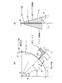
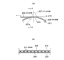
(1)表面張力利用型: 図13は従来の表面張力利用型の塗工ヘッダを用いた薄膜形成装置の一例の構成及び作動を説明するための模式的な要部側断面図である。   (1) Surface Tension Utilizing Type: FIG. 13 is a schematic side sectional view for explaining the configuration and operation of an example of a thin film forming apparatus using a conventional surface tension utilizing type coating header.

この薄膜形成装置200では、図13(a)に示すように、薄膜を形成する材料液(塗工液)aをポンプPにより液供給管202を介して塗工ヘッダとしての円柱体201の空洞(内部)201aへ供給する。この円柱体201の上部には、20μm程度の径の孔が多数形成されたポーラス部(塗工部)203が、周方向に10mm程度の幅をもって形成されており、このポーラス部203においては、円柱体201の外周面と内周面とが連通した状態となっている。したがって、ポンプPにより上記の内部201aへと供給された材料液aは、ポーラス部203において外周面へ供給されるようになるが、この外周面へ供給された材料液aの内、過剰に供給された材料液aは、円柱体201の姿勢がポーラス部203を鉛直上方に向けた姿勢に設定されているため、ポーラス部203を出た後、下方に落下するようになる。   In this thin film forming apparatus 200, as shown in FIG. 13A, a material liquid (coating liquid) a for forming a thin film is pumped by a pump P through a liquid supply pipe 202 to form a hollow body of a cylindrical body 201 as a coating header. (Internal) Supply to 201a. A porous portion (coating portion) 203 in which a large number of holes having a diameter of about 20 μm are formed is formed with a width of about 10 mm in the circumferential direction at the upper portion of the cylindrical body 201. In the porous portion 203, The outer peripheral surface and the inner peripheral surface of the cylindrical body 201 are in communication with each other. Therefore, the material liquid a supplied to the inner part 201a by the pump P is supplied to the outer peripheral surface in the porous portion 203. However, the material liquid a supplied to the outer peripheral surface is excessively supplied. Since the posture of the cylindrical body 201 is set to a posture in which the porous portion 203 is directed vertically upward, the material liquid “a” thus dropped falls downward after exiting the porous portion 203.

この結果、ポーラス部203にはその外周面に一定高さ(例えば400μm程度)の材料液aの隆起が得られるようになる。そして、図13(b)に示すように、基材(被薄膜形成材)210を、ポーラス部203における材料液aの隆起に接触させつつ移動させることで、基材210に材料液aの液溜まり(液ビード:液膜)204が形成される。   As a result, the porous portion 203 can be raised on the outer peripheral surface thereof with the material liquid a having a certain height (for example, about 400 μm). And as shown in FIG.13 (b), the base material (thin film forming material) 210 is moved in contact with the bulge of the material liquid a in the porous portion 203, whereby the liquid of the material liquid a is transferred to the base material 210. A pool (liquid bead: liquid film) 204 is formed.

なお、円柱体201の外周面から落下した材料液aは、円柱体201の下方に配置された液タンク205により回収され、液回収管206を介してポンプPに吸引され、再び円柱体201へと供給されることとなる。   The material liquid a dropped from the outer peripheral surface of the cylindrical body 201 is collected by a liquid tank 205 disposed below the cylindrical body 201, sucked by the pump P through the liquid recovery pipe 206, and returned to the cylindrical body 201 again. Will be supplied.

(2)毛細管現象利用型(キャピラリーコータ型): 図14は従来の毛細管現象利用型の塗工ヘッダを用いた薄膜形成装置の一例の構成及び作動を説明するための模式的な要部側断面図である。   (2) Capillary Phenomenon Utilization Type (Capillary Coater Type): FIG. 14 is a schematic side cross-sectional view for explaining the configuration and operation of an example of a thin film forming apparatus using a conventional capillary phenomenon utilization type coating header. FIG.

この薄膜形成装置300では、非塗工作業時には、塗工ヘッダ301を材料液層302に沈めておき、塗工作業時には、塗工ヘッダ301の先端を、上記材料液層302から基材(被薄膜形成材)310に向けて突出させるようになっている。塗工ヘッダ301には基材310の移動方向に対し略直角方向に配向して開口するスリット303が形成されており、上記材料液層302を形成する材料液aが、毛細現象によりこのスリット303内を伝って塗工ヘッダ301の先端で隆起して液ビード(液溜まり)304を形成する。この液ビード304は材料液aの表面張力によりその隆起高さひいてはその量がほぼ一定に保たれる。   In the thin film forming apparatus 300, the coating header 301 is submerged in the material liquid layer 302 during the non-coating operation, and the tip of the coating header 301 is moved from the material liquid layer 302 to the substrate (covered) during the coating operation. It protrudes toward the (thin film forming material) 310. The coating header 301 is formed with a slit 303 that is oriented and opened in a direction substantially perpendicular to the moving direction of the substrate 310, and the material liquid a that forms the material liquid layer 302 is caused by the capillary phenomenon. A liquid bead (liquid pool) 304 is formed by rising at the tip of the coating header 301 through the inside. This liquid bead 304 is kept substantially constant in height by extension of its height due to the surface tension of the material liquid a.

そして、塗工ヘッダ301の先端に液溜まり304が形成された状態で、塗工ヘッダ301に対し所定の隙間(ギャップ)をあけつつ且つ基材310を液溜まり304に接触させて基材310を移動させることで、基材310に材料液aが塗工される。   Then, with the liquid pool 304 formed at the tip of the coating header 301, the base material 310 is brought into contact with the liquid pool 304 while leaving a predetermined gap (gap) with respect to the coating header 301. By moving it, the material liquid a is applied to the base material 310.

このような塗工作業時は、基材310に塗工される分、液溜まり304が減少することとなるが、この減少した分だけ材料液aが、毛細管現象により自然と一定に液溜まり304に供給されるしくみとなっている。   During such a coating operation, the liquid pool 304 is reduced by the amount applied to the base material 310, but the material liquid a is naturally and constantly pooled 304 by the capillary phenomenon. It is a mechanism to be supplied to.

塗工作業は、図14において(a)〜(f)の順に行われ、先ず、塗工開始前においては、(a)に示すように、塗工ヘッダ301は液タンク305内に沈められており、この液タンク305の上部は蓋306に蓋われている。   The coating work is performed in the order of (a) to (f) in FIG. 14. First, before the start of coating, as shown in (a), the coating header 301 is submerged in the liquid tank 305. The upper part of the liquid tank 305 is covered with a lid 306.

次いで、(b)に示すように、蓋306がスライドして液タンク305が開放され、塗工ヘッダ301が液タンク305から基材310側へ突出した状態とされる。この時、液タンク305内の材料液aが、毛細管現象により、塗工ヘッダ301に形成されたスリット303を上昇して塗工ヘッダ301の先端で隆起して液溜まり304を形成する。   Next, as shown in (b), the lid 306 slides to open the liquid tank 305, and the coating header 301 protrudes from the liquid tank 305 to the substrate 310 side. At this time, the material liquid a in the liquid tank 305 rises up the slit 303 formed in the coating header 301 by the capillary phenomenon and rises at the tip of the coating header 301 to form a liquid pool 304.

そして、このような塗工ヘッダ301の状態において、(c)、(d)、(e)に示すように、基材310を塗工ヘッダ301の先端の液溜まり304に接触させながら、基材301のセットされるステージ307と一体に図中左側へとスライドさせて行き、この過程で、基材310に塗工薄膜308が次第に形成されていく。(f)に示すように、基材310が液溜まり304を通過して塗工が完了すると、塗工ヘッダ301は液タンク305内の材料液層302に沈められた後、蓋306がスライドして液タンク305を蓋い、塗工作業が完了する。   And in such a state of the coating header 301, as shown in (c), (d), (e), the base material 310 is brought into contact with the liquid pool 304 at the tip of the coating header 301, The substrate 301 is slid to the left in the drawing integrally with the stage 307 on which 301 is set. In this process, the coating thin film 308 is gradually formed on the substrate 310. As shown in (f), when the base material 310 passes through the liquid pool 304 and the coating is completed, the coating header 301 is submerged in the material liquid layer 302 in the liquid tank 305, and then the lid 306 slides. Then, the liquid tank 305 is covered and the coating operation is completed.

しかしながら、上述した2つのタイプの従来の薄膜形成装置用の塗工ヘッダには依然以下のような問題があった。   However, the above-described two types of conventional coating headers for thin film forming apparatuses still have the following problems.

(1)表面張力利用型
図15は上述した図13に示すような従来の表面張力利用型の塗工ヘッダとしての円柱体201の問題の説明図であって、(a)は基材210と円柱体201のポーラス部(塗工部)203との最接近部(以下、ニップ部という)の模式的な側面視による断面図であり、(b)は(a)の模式的なA−A矢視断面図である。
(1) Surface Tension Utilization Type FIG. 15 is an explanatory view of the problem of the cylindrical body 201 as a conventional surface tension utilization type coating header as shown in FIG. It is sectional drawing by typical side view of the closest part (henceforth nip part) with the porous part (coating part) 203 of the cylindrical body 201, (b) is typical AA of (a). It is arrow sectional drawing.

図15(a)中の破線207は、基材210とポーラス部203とのニップ部周辺で材料液膜208、209が受ける圧力の圧力分布線を示し、図15(a)中で上にあるほど高い圧力を示している。基材210とポーラス部203との隙間が狭いほど材料液aが受ける圧力は高くなることから、ニップ部において材料液aが絞られる(これを液絞りという)ため材料液aの圧力は急上昇する一方、ニップ部下流側では基材210とポーラス部203との隙間が急に広がるため、材料液の圧力は負圧となる(圧力分布線207における符号207aで示す部分を参照)。   A broken line 207 in FIG. 15A indicates a pressure distribution line of the pressure received by the material liquid films 208 and 209 around the nip portion between the base material 210 and the porous portion 203, which is on the upper side in FIG. The higher pressure is shown. The narrower the gap between the substrate 210 and the porous portion 203, the higher the pressure received by the material liquid a. Therefore, since the material liquid a is squeezed at the nip (this is called liquid squeezing), the pressure of the material liquid a rapidly increases. On the other hand, since the gap between the substrate 210 and the porous portion 203 suddenly widens on the downstream side of the nip portion, the pressure of the material liquid becomes negative (see the portion indicated by reference numeral 207a in the pressure distribution line 207).

この負圧の発生のため、ニップ部下流側で液膜分裂の際、すなわちポーラス部の材料液膜208の一部が基材210へ材料液膜209として移動する際、上記負圧の作用により材料液膜208、209のメニスカスが基材210とポーラス部203との隙間に引き込まれるような現象が発生し、図15(b)に示すように、材料液膜208、209に規則的なリングパターンと呼ばれる円柱体201円周方向に延びる筋状のムラ(円柱体201軸方向に数mm程度のピッチで繰り返される液厚の凹凸)が発生しやすい。図15(b)中の符号211はリングパターンを形成し基材210に正常に塗工されない余剰液(余剰な材料液)である。リングパターンの凹凸のピッチや高さは、材料液aの表面張力や粘度及びニップ部下流側で発生する負圧207aの程度により異なったものとなる。   Due to the generation of the negative pressure, when the liquid film is split on the downstream side of the nip portion, that is, when a part of the material liquid film 208 in the porous portion moves to the base material 210 as the material liquid film 209, the negative pressure acts as described above. A phenomenon occurs in which the meniscus of the material liquid films 208 and 209 is drawn into the gap between the base 210 and the porous portion 203, and as shown in FIG. 15B, a regular ring is formed on the material liquid films 208 and 209. It is easy to generate streak-like unevenness called a pattern that extends in the circumferential direction of the cylinder 201 (liquid thickness unevenness repeated at a pitch of about several mm in the axis direction of the cylinder 201). Reference numeral 211 in FIG. 15B denotes an excess liquid (excess material liquid) that forms a ring pattern and is not normally applied to the substrate 210. The pitch and height of the unevenness of the ring pattern differ depending on the surface tension and viscosity of the material liquid a and the degree of the negative pressure 207a generated on the downstream side of the nip portion.

このようなリングパターンが発生すると、基材210が印刷版である場合には、この印刷版を使用して印刷された印刷物にリングパターンに応じた濃淡ムラが生じ、不良印刷物となる。また、その問題のほかに、表面張力利用型の塗工ヘッダの一般的傾向として、塗工速度はある程度高速化できるが、薄膜形成の精度を十分に上げられない、という問題もあった。   When such a ring pattern is generated, if the substrate 210 is a printing plate, unevenness in density corresponding to the ring pattern is generated on a printed material printed using the printing plate, resulting in a defective printed material. In addition to this problem, the general tendency of surface tension-based coating headers is that the coating speed can be increased to some extent, but the accuracy of thin film formation cannot be sufficiently increased.

(2)毛細管現象利用型(キャピラリーコータ型)
図16は上述した図14に示すような従来の毛細管現象利用型の塗工ヘッダ301の問題の説明図であって、(a)は基材310と塗工ヘッダ301との最接近部(以下、ニップ部という)の模式的な側面視による断面図であり、(b)は(a)の模式的なB−B矢視断面図である。
(2) Capillary phenomenon type (capillary coater type)
FIG. 16 is an explanatory view of the problem of the conventional capillary phenomenon-based coating header 301 as shown in FIG. 14, wherein (a) is the closest part (hereinafter referred to as the base material 310 and the coating header 301). FIG. 2 is a cross-sectional view taken along a schematic side view of a nip portion), and FIG.

毛細管現象利用型の塗工ヘッダ301も、上記の表面張力利用型の塗工ヘッダとしての円柱体201と同様の課題を有する。つまり、塗工ヘッダ301の基材310移動方向下流側では、それまで塗工ヘッダ301の上面により規定されていた空間が急激に広がるので、負圧部309が発生し、材料液aの液溜まり304の一部が基材310上の塗工薄膜308へと移動する液膜分裂の際、材料液aのメニスカスが塗工ヘッダ301側に引き込まれてしまう。この結果、(b)に示すような基材310移動方向に対して直角方向において数mmピッチで凹凸が繰り返されるリングパターンが発生しやすくなるのである。(b)中の符号311はリングパターンを形成し基材310に正常に塗工されない余剰液(余剰な材料液)である。   The capillary phenomenon-based coating header 301 also has the same problems as the cylindrical body 201 as the surface tension-based coating header. That is, on the downstream side of the coating header 301 in the movement direction of the base material 310, the space defined by the upper surface of the coating header 301 is rapidly expanded so that a negative pressure portion 309 is generated and the liquid material a is pooled. At the time of liquid film splitting in which part of 304 moves to the coating thin film 308 on the substrate 310, the meniscus of the material liquid a is drawn to the coating header 301 side. As a result, a ring pattern in which irregularities are repeated at a pitch of several mm in the direction perpendicular to the direction of movement of the base material 310 as shown in FIG. Reference numeral 311 in (b) is an excess liquid (excess material liquid) that forms a ring pattern and is not normally applied to the substrate 310.

また、この毛細管現象利用型の塗工ヘッダ301では、スリット303の幅(スリット開口幅)と塗工ヘッダ301の先端から基材310の表面までの距離との関係を制御できれば、均一な薄膜の形成(リングパターンの発生を抑制すること)は可能であるが、上記スリット開口幅を装置幅方向[図15(a)において紙面に垂直な方向]に亘って均一に加工するのが難しく、塗工ヘッダ301と基材310との距離に応じてスリット開口幅を適切に調整するのは現実的には難しいという問題があった。また、その問題のほかに、毛細管現象利用型の塗工ヘッダの一般的傾向として、薄膜形成の精度を上げることができ美麗な塗膜が得やすいが、塗工速度が低いという問題があり、材料液aの供給を単に毛細管現象によらずポンプ等圧送手段を用いることである程度速度向上ができるが薄膜精度との関係から限界がある。   Further, in this coating header 301 utilizing capillary action, if the relationship between the width of the slit 303 (slit opening width) and the distance from the tip of the coating header 301 to the surface of the substrate 310 can be controlled, a uniform thin film can be formed. It is possible to form (suppress the generation of the ring pattern), but it is difficult to uniformly process the slit opening width in the apparatus width direction [direction perpendicular to the paper surface in FIG. There is a problem that it is actually difficult to appropriately adjust the slit opening width according to the distance between the work header 301 and the base material 310. In addition to that problem, as a general tendency of capillary action type coating headers, it is easy to obtain a beautiful coating film that can improve the accuracy of thin film formation, but there is a problem that the coating speed is low, The supply of the material liquid a can be improved to some extent by simply using a pump-feeding means irrespective of the capillary phenomenon, but there is a limit in relation to the thin film accuracy.

以上、従来の(1)表面張力利用型、及び(2)毛細管現象利用型の塗工ヘッダにつき、平板状の基材(被薄膜形成材)に直接薄膜を形成する場合を説明したが、シリンダ状の基材(被薄膜形成材)210、310に薄膜を塗工する場合や、図12で説明したような、被塗工材としての薄膜塗工ローラに一旦塗工した上で薄膜塗工ローラから基材(被薄膜形成材)210、310に転写するときの薄膜塗工ローラへの塗工の場合は、被塗工材(基材または薄膜塗工ローラ等)がシリンダ状物であり、そのシリンダ状物をその軸芯線を中心に回転させつつ、円柱体201又は塗工ヘッダ301により塗工を行うことにより、シリンダ状物の周面に連続的に薄膜を形成するが、同様に上記のリングパターンや薄膜精度、塗工速度の問題を有するものであった。   As described above, the conventional (1) surface tension type and (2) capillary phenomenon type coating headers have been described in the case where a thin film is directly formed on a flat substrate (film forming material). When a thin film is applied to the base materials (film forming materials) 210 and 310, or a thin film coating roller once applied to a thin film coating roller as a coating material as described in FIG. In the case of coating onto a thin film coating roller when transferring from a roller to a substrate (film forming material) 210, 310, the material to be coated (such as a substrate or a thin film coating roller) is a cylinder. The thin film is continuously formed on the peripheral surface of the cylindrical object by coating with the cylindrical body 201 or the coating header 301 while rotating the cylindrical object about the axis. The ring pattern, thin film accuracy, and coating speed It was.

特開2001−62370公報(第2頁、図5、6)JP 2001-62370 A (2nd page, FIGS. 5 and 6)

以上のように、(1)表面張力利用型及び(2)毛細管現象利用型の何れの塗工ヘッダ201、301においても、塗工薄膜の厚みが塗工方向に対する幅方向において不均一になりやすく、リングパターンに応じた濃淡ムラが生じ、不良印刷物(損紙)となる問題があった。   As described above, in any of the coating headers 201 and 301 of (1) surface tension utilization type and (2) capillary action utilization type, the thickness of the coating thin film tends to be uneven in the width direction with respect to the coating direction. In addition, there is a problem that unevenness in density according to the ring pattern occurs, resulting in defective printed matter (damaged paper).

なお、上記問題点の説明においても、被塗工材として平板状の基材(被薄膜形成材)210、310に塗工膜を形成する例を説明したが、リングパターンは被塗工材(基材または薄膜塗工ローラ等)がシリンダ状物の場合にも発生し、シリンダ状の基材(被薄膜形成材)に薄膜を塗工する場合であっても同様であり、また、図12で説明したと同様に、薄膜塗工ローラに一旦塗工した上で薄膜塗工ローラから基材(被薄膜形成材)210、310に転写する場合の、薄膜塗工ローラへの塗工の場合も同様のリングパターンが生じ、その結果、基材(被薄膜形成材)210、310上のリングパターンの問題を発生する。   In the description of the above problem, the example in which the coating film is formed on the flat base materials (thin film forming materials) 210 and 310 as the coating material has been described. This also occurs when the base material or the thin film coating roller is a cylindrical object, and the same applies to the case where a thin film is applied to the cylindrical base material (film forming material). In the same manner as described in the above, in the case of coating on the thin film coating roller when the thin film coating roller is once coated and then transferred from the thin film coating roller to the base material (film forming material) 210, 310 , A similar ring pattern is generated, and as a result, a problem of the ring pattern on the base materials (thin film forming materials) 210 and 310 occurs.

本発明はこのような問題を解決するためになされたものであり、被塗工材(基材または薄膜塗工ローラ等)に均一の厚みで、安定した材料液を塗工でき、塗工速度の向上を可能とする、薄膜形成装置用の材料液の塗工ヘッダと、それを用いた薄膜形成装置を提供することを課題とする。   The present invention has been made to solve such problems, and can apply a stable material solution to a material to be coated (such as a base material or a thin film coating roller) with a uniform thickness, and a coating speed. It is an object of the present invention to provide a coating header of a material liquid for a thin film forming apparatus and a thin film forming apparatus using the same.

本発明は、上記の課題を解決するためになされ、下記の(1)から(8)の手段を提供するものであり、以下、特許請求の範囲に記載の順に説明する。   The present invention has been made to solve the above-described problems, and provides the following means (1) to (8), and will be described below in the order of the claims.

(1)その第1の手段として、液状の材料液を被塗工材の塗工面に塗布し、同塗工面に薄膜を形成する薄膜形成装置用の塗工ヘッダであって、前記材料液を前記被塗工材に供給する前記塗工ヘッダ先端のリップ部におけるリップ下流側面が同塗工ヘッダ中心線に対して0°ないし20°の範囲で前記塗工面側に傾斜して加工されてなることを特徴とする塗工ヘッダを提供する。   (1) As the first means, it is a coating header for a thin film forming apparatus that applies a liquid material solution to a coated surface of a material to be coated and forms a thin film on the coated surface. The lip downstream side surface of the lip portion at the tip of the coating header supplied to the coating material is processed by being inclined toward the coating surface within a range of 0 ° to 20 ° with respect to the coating header center line. A coating header is provided.

(2)第2の手段としては、第1の手段の塗工ヘッダにおいて、下方に向き水平方向に対して20°ないし65°の塗工面角度をつけた前記被塗工材の塗工面に、前記リップ部を上向きに近接配置されてなることを特徴とする塗工ヘッダを提供する。   (2) As the second means, in the coating header of the first means, the coating surface of the material to be coated with a coating surface angle of 20 ° to 65 ° with respect to the horizontal direction facing downward, Provided is a coating header characterized in that the lip portion is closely arranged upward.

(3)また、第3の手段として、第1の手段または第2の手段の塗工ヘッダにおいて、同塗工ヘッダはその中心方向を、前記リップ部が近接配置された箇所の前記塗工面に垂直に向け配置されてなることを特徴とする塗工ヘッダを提供する。   (3) Further, as a third means, in the coating header of the first means or the second means, the coating header has its center direction on the coating surface at the location where the lip portion is disposed in proximity. Provided is a coating header characterized by being arranged vertically.

(4)第4の手段として、第1の手段ないし第3の手段のいずれかの塗工ヘッダにおいて、前記液状の材料液が揮発性の材料液であることを特徴とする塗工ヘッダを提供する。   (4) As a fourth means, in the coating header of any one of the first means to the third means, a coating header is provided in which the liquid material liquid is a volatile material liquid To do.

(5)第5の手段として、第1の手段ないし第4の手段のいずれかの塗工ヘッダにおいて、前記被塗工材は平板状被塗工材であり、前記リップ部が近接配置される前記塗工面は同平板状被塗工材の下面であることを特徴とする塗工ヘッダを提供する。   (5) As a fifth means, in the coating header of any one of the first means to the fourth means, the material to be coated is a flat material to be coated, and the lip portion is disposed in proximity. The coating surface is a lower surface of the flat plate-shaped material to be coated, and provides a coating header.

(6)第6の手段として、第1の手段ないし第4の手段のいずれかの塗工ヘッダにおいて、前記被塗工材はシリンダ状被塗工材であり、前記リップ部が近接配置される塗工面は同シリンダ状被塗工材の下側周面であることを特徴とする塗工ヘッダを提供する。   (6) As a sixth means, in the coating header of any one of the first means to the fourth means, the coated material is a cylindrical coated material, and the lip portion is disposed in proximity. The coating surface is a lower peripheral surface of the cylindrical coated material, and provides a coating header.

(7)第7の手段として、第1の手段ないし第6の手段のいずれかの塗工ヘッダを備えてなることを特徴とする薄膜形成装置を提供する。   (7) As a seventh means, there is provided a thin film forming apparatus comprising the coating header of any one of the first means to the sixth means.

(8)第8の手段として、第1の手段ないし第4の手段、または第6の手段のいずれかの塗工ヘッダを備えてなることを特徴とする反転印刷装置を提供する。   (8) As an eighth means, there is provided a reverse printing apparatus comprising the coating header of any one of the first means to the fourth means or the sixth means.

(1)特許請求の範囲に記載の請求項1の発明によれば、リップ下流側面がシャープエッジまたはそれに近い形状のため、リップ上流側面への液拡張濡れが抑制され、材料液固着が発生しない条件となり、被塗工材に均一の厚みで、安定したビード形状で材料液を塗工でき、リングパターンの問題を回避し塗工速度向上が可能となる。   (1) According to the invention of claim 1, since the lip downstream side surface has a sharp edge or a shape close thereto, liquid expansion wetting to the lip upstream side surface is suppressed, and material liquid adhesion does not occur. The material liquid can be applied to the material to be coated in a uniform bead shape with a stable bead shape, avoiding the problem of the ring pattern and improving the coating speed.

(2)請求項2の発明によれば、請求項1の発明の作用効果に加え、鉛直方向液引出し力が大きくなり液ビードが安定、塗工開始前の液だれが防止されて膜厚誤差の増大が防止されるので、さらに、材料液固着が発生しない条件となり、被塗工材に均一の厚みで、安定したビード形状で材料液aを塗工でき、リングパターンの問題を回避し塗工速度向上が可能となる。   (2) According to the invention of claim 2, in addition to the function and effect of the invention of claim 1, the vertical liquid drawing force is increased, the liquid bead is stable, and dripping before the start of coating is prevented, resulting in film thickness error. In addition, the material liquid is not fixed, and the material liquid a can be applied to the material to be coated with a uniform thickness and a stable bead shape, avoiding ring pattern problems and coating. The work speed can be improved.

(3)請求項3の発明によれば、通常の塗工面と垂直な配置方向に取付けた塗工ヘッダにおいて請求項1または請求項2の発明の作用効果をさらに奏することができる。   (3) According to the invention of claim 3, the effect of the invention of claim 1 or claim 2 can be further exerted in the coating header attached in the arrangement direction perpendicular to the normal coating surface.

(4)請求項4の発明によれば、特に、材料液の固着が生じやすかった揮発性の材料液を塗工する場合において、請求項1ないし請求項3のいずれかの発明の作用効果を顕著に奏することができる。   (4) According to the invention of claim 4, particularly in the case of applying a volatile material liquid in which the material liquid is easily fixed, the effect of the invention of any one of claims 1 to 3 is achieved. It can play remarkably.

(5)請求項5の発明によれば、請求項1ないし請求項4のいずれかの発明の作用効果を、平板状被塗工材の下面を塗工面として奏することができる。   (5) According to the invention of claim 5, the effect of the invention of any one of claims 1 to 4 can be achieved with the lower surface of the flat coated material as the coating surface.

(6)請求項6の発明によれば、請求項1ないし請求項4のいずれかの発明の作用効果を、シリンダ状被塗工材の下側周面を塗工面として奏することができる。   (6) According to the invention of claim 6, the effect of the invention of any one of claims 1 to 4 can be achieved with the lower peripheral surface of the cylindrical coated material as the coating surface.

(7)請求項7の発明によれば、薄膜形成装置において、請求項1ないし請求項6のいずれかの発明の作用効果を奏し、基材または薄膜塗工ローラ等の被塗工材に、均一の厚みで、安定した液ビード形状で、材料液を塗工でき、リングパターンの問題を回避し、塗工精度、塗工速度向上が可能な薄膜形成装置となる。   (7) According to the invention of claim 7, in the thin film forming apparatus, the effect of the invention of any one of claims 1 to 6 is achieved, and the coated material such as a base material or a thin film coating roller, With a uniform thickness and a stable liquid bead shape, the material liquid can be applied, a ring pattern problem can be avoided, and a thin film forming apparatus capable of improving coating accuracy and coating speed.

(8)請求項8の発明によれば、反転印刷装置において、請求項1ないし請求項4、または請求項6のいずれかの発明の作用効果を奏し、塗布胴等の被塗工材に、均一の厚みで、安定した液ビード形状で材料液を塗布でき、リングパターン等の問題を回避し、塗工精度、塗工速度向上が可能な反転印刷装置となる   (8) According to the invention of claim 8, in the reversal printing apparatus, the effects of the invention of any one of claims 1 to 4 or claim 6 are achieved, It is a reversal printing device that can apply a material liquid in a uniform liquid bead shape with a uniform thickness, avoid problems such as ring patterns, and improve coating accuracy and coating speed.

本発明を実施するための最良の形態として、以下に実施例1から実施例3を説明する。   Examples 1 to 3 will be described below as the best mode for carrying out the present invention.

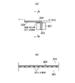
本発明の実施例1に係る塗工ヘッダを図1に基づき説明する。図1(a)はシリンダ状被塗工材に対する本実施例の塗工ヘッダの配置図であり、(b)は本実施例の塗工ヘッダの拡大断面図である。本実施例の塗工ヘッダは、図12に示すと同様の薄膜形成装置に用いられる塗工ヘッダであり、薄膜形成装置全体は図12を参照することとし、改めて図示することは省略する。なお、本実施例において、薄膜形成装置100は図12に図示のものに限定されることなく、種々の態様のものであってよい。   The coating header which concerns on Example 1 of this invention is demonstrated based on FIG. FIG. 1A is an arrangement view of a coating header of this embodiment with respect to a cylindrical coated material, and FIG. 1B is an enlarged cross-sectional view of the coating header of this embodiment. The coating header of the present embodiment is a coating header used in the same thin film forming apparatus as shown in FIG. 12, and the entire thin film forming apparatus will be referred to FIG. 12, and will not be illustrated again. In this embodiment, the thin film forming apparatus 100 is not limited to the one shown in FIG.

図1において、1は本実施例の塗工ヘッダであり、10は塗工ヘッダ1により材料液(塗工液)aの薄膜を塗工されるシリンダ状被塗工材である。材料液aは揮発性の材料液も含むものとする。シリンダ状被塗工材10は、例えば、各種基板等の基材(被薄膜形成材)であり、または、材料液aを基材に転写する薄膜塗工ローラ等であって、シリンダ状に形成され、その軸芯線O回りに図中矢印方向に回転しつつ、その周面10a(塗工面)に近接する塗工ヘッダ1によって塗工され、周面10a上に材料液aの液ビード4が形成される。   In FIG. 1, reference numeral 1 denotes a coating header of the present embodiment, and reference numeral 10 denotes a cylindrical coated material to be coated with a thin film of a material liquid (coating liquid) a by the coating header 1. The material liquid a includes a volatile material liquid. The cylindrical coating material 10 is, for example, a base material (film forming material) such as various substrates, or a thin film coating roller that transfers the material liquid a to the base material, and is formed in a cylinder shape. Then, while rotating in the direction of the arrow in the drawing around the axis O, it is applied by the coating header 1 close to the peripheral surface 10a (coating surface), and the liquid bead 4 of the material liquid a is formed on the peripheral surface 10a. It is formed.

塗工ヘッダ1は、図14で説明したと同様に毛細管現象利用型の塗工ヘッダであり、その内部に設けられスリット13を有し、スリット13は塗工ヘッダ1の先端部(以下、「リップ部」という)1aに開口を有し、毛細管現象を利用して材料液aをシリンダ状被塗工材10の周面10aに供給する。なお、毛細管現象による以上に塗工速度を増大させる必要のある場合は材料液aをポンプ等により加圧して供給することがある。   The coating header 1 is a capillary phenomenon-based coating header as described with reference to FIG. 14, and has a slit 13 provided therein. The slit 13 is a tip of the coating header 1 (hereinafter, “ 1a) having an opening, and supplying the material liquid a to the peripheral surface 10a of the cylindrical coating material 10 by utilizing capillary action. In addition, when it is necessary to increase the coating speed more than by the capillary phenomenon, the material liquid a may be supplied under pressure by a pump or the like.

塗工ヘッダ1のリップ部1aが位置するシリンダ状被塗工材10の下側の周面10aの点の、シリンダ状被塗工材10の下側の周面10aの真下の位置からの角度、すなわちシリンダ状被塗工材10の軸芯Oと塗工ヘッダ1とを結ぶ線と鉛直方向Yとのなす角度をθとすると、塗工ヘッダ1のリップ部1aに相対し、塗工されるシリンダ状被塗工材10の周面10a(塗工面)の傾斜角度、すなわち接線方向の角度は、水平方向Xに対してθとなる(以下、「塗工面角度θ」という)。   The angle of the point on the lower peripheral surface 10a of the cylindrical coating material 10 where the lip 1a of the coating header 1 is located from the position directly below the lower peripheral surface 10a of the cylindrical coating material 10 In other words, when the angle formed between the line connecting the axis O of the cylindrical coating material 10 and the coating header 1 and the vertical direction Y is θ, the coating is performed opposite to the lip portion 1a of the coating header 1. The angle of inclination of the peripheral surface 10a (coating surface) of the cylindrical coated material 10, that is, the angle in the tangential direction is θ with respect to the horizontal direction X (hereinafter referred to as “coating surface angle θ”).

本実施例において、塗工ヘッダ1のリップ部1a(以下、単に「塗工ヘッダ1」とも記載する)は、シリンダ状被塗工材10の下側の周面10aの真下の位置から鉛直方向Yに対してθ回った点の周面10aに位置しており、θは、θ1=25°からθ2=65°の範囲、θ=25〜65°に設定される。すなわち塗工面角度θ=25〜65°に設定される。   In the present embodiment, the lip portion 1a of the coating header 1 (hereinafter also simply referred to as “coating header 1”) is perpendicular to the position directly below the lower peripheral surface 10a of the cylindrical coated material 10. It is located on the peripheral surface 10a at a point θ turned with respect to Y, and θ is set in the range of θ1 = 25 ° to θ2 = 65 °, θ = 25 to 65 °. That is, the coating surface angle θ is set to 25 to 65 °.

なお、通常、塗工ヘッダ1は、塗工ヘッダ中心線Cを略シリンダ状被塗工材10の軸芯線Oに向けて、リップ部1aが近接配置された箇所の周面10a(塗工面)の方向、すなわち同箇所の接線方向と略垂直に配向されるから、塗工ヘッダ中心線Cの鉛直方向Yに対する角度もθ=25〜65°の範囲になる。   Normally, the coating header 1 has a peripheral surface 10a (coating surface) at a location where the lip portion 1a is disposed close to the coating header center line C toward the axis O of the substantially cylindrical coating material 10. The direction of the coating header center line C with respect to the vertical direction Y is also in the range of θ = 25 to 65 °.

塗工ヘッダ1の断面形状は図1(b)に示すように、シリンダ状被塗工材10の回転方向における上流側のリップ上流側面11と、下流側のリップ下流側面12の間に、塗工ヘッダ中心線Cに沿ってスリット13が形成されている。スリット13はリップ部1aにおいて、周面10aに面してシリンダ状被塗工材10の軸方向に延在する開口を有し、そこから周面10aへの材料液aの供給を行う。   As shown in FIG. 1B, the cross-sectional shape of the coating header 1 is applied between the upstream lip upstream side surface 11 and the downstream lip downstream side surface 12 in the rotation direction of the cylindrical coating material 10. A slit 13 is formed along the work header center line C. The slit 13 has an opening extending in the axial direction of the cylindrical coating material 10 facing the peripheral surface 10a in the lip portion 1a, and supplies the material liquid a to the peripheral surface 10a therefrom.

スリット13の開口幅dは例えば0.5〜0.8mmであり、スリット13を挟むリップ上流側面11側とリップ下流側面12側の先端部材厚さはそれぞれ5mm程度である。リップ下流側面12は塗工ヘッダ中心線Cに対し、角度αの周面10a(塗工面)側に傾斜した面をなすように加工されており、α=0〜20°の範囲、さらに好ましくはα=5〜20°の範囲としてある。   The opening width d of the slit 13 is, for example, 0.5 to 0.8 mm, and the tip member thicknesses on the lip upstream side surface 11 side and the lip downstream side surface 12 side sandwiching the slit 13 are each about 5 mm. The lip downstream side surface 12 is processed so as to form a surface inclined to the peripheral surface 10a (coating surface) side at an angle α with respect to the coating header center line C, and more preferably in a range of α = 0 to 20 °. α is in the range of 5 to 20 °.

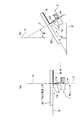
本発明の実施例2に係る塗工ヘッダを図2(a)に基づき説明する。図2(a)は平板状被塗工材に対する本実施例の塗工ヘッダの配置図である。本実施例の塗工ヘッダも、実施例1と同じく、図12に示すと同様の薄膜形成装置に用いられる塗工ヘッダ1であり、平板状被塗工材に対するものである以外は、塗工ヘッダ1の構造も薄膜形成装置全体も実施例1で記載したと同様であり、繰り返しの記載は省略する。   The coating header which concerns on Example 2 of this invention is demonstrated based on Fig.2 (a). FIG. 2A is a layout view of the coating header of this embodiment with respect to the flat plate-shaped material to be coated. Similarly to Example 1, the coating header of this example is a coating header 1 used in the same thin film forming apparatus as shown in FIG. 12, except that it is for a flat coated material. The structure of the header 1 and the entire thin film forming apparatus are the same as those described in the first embodiment, and repeated description is omitted.

図2(a)において、20は塗工ヘッダ1により材料液aの薄膜を塗工される平板状被塗工材である。材料液aは揮発性の材料液もである含むものとする。平板状被塗工材20は、例えば、各種基板等の平板状の基材(被薄膜形成材)であり、水平軸Xに沿って配置され、水平軸X方向に移動されつつ、その下面(塗工面)に略垂直上向きに近接する塗工ヘッダ1によって塗工され、面上に材料液aの液ビード4が形成される。従って、平板状被塗工材20の水平方向Xに対する塗工面角度θ=0°である。   In FIG. 2A, reference numeral 20 denotes a flat plate-like material to be coated with a thin film of the material liquid “a” by the coating header 1. The material liquid “a” includes a volatile material liquid. The flat coating material 20 is, for example, a flat base material (film forming material) such as various substrates, and is arranged along the horizontal axis X and is moved in the horizontal axis X direction while its lower surface ( The coating bead 4 of the material liquid a is formed on the surface. Accordingly, the coating surface angle θ = 0 ° with respect to the horizontal direction X of the flat plate-shaped material 20.

なお、通常、塗工ヘッダ1は、塗工ヘッダ中心線Cを平板状被塗工材20の下面(塗工面)に略垂直に配向されるから、塗工ヘッダ中心線Cの鉛直方向Yに対する角度もθ=0°になる。   In general, the coating header 1 is oriented with the coating header center line C substantially perpendicular to the lower surface (coating surface) of the flat plate-shaped material 20, so that the coating header center line C is perpendicular to the vertical direction Y. The angle is θ = 0 °.

塗工ヘッダ1は、実施例1と同様のものであり、内部に設けられ毛細管現象を利用して材料液aを供給するスリット13を有し、塗工ヘッダ中心線Cを平板状被塗工材20に略垂直に向けてリップ部1aを近接させて設置されている。塗工ヘッダ1の断面形状は図1(b)に示すものと同じであり、リップ下流側面12は塗工ヘッダ中心線Cに対し塗工面側に傾斜する、角度αの傾斜面をなし、α=0〜20°、さらに好ましくはα=5〜20°としてある。   The coating header 1 is the same as that of the first embodiment, has a slit 13 that is provided inside and supplies the material liquid a by utilizing a capillary phenomenon, and the coating header center line C is formed into a flat plate-like coating. The lip portion 1a is placed close to the material 20 in a substantially vertical direction. The cross-sectional shape of the coating header 1 is the same as that shown in FIG. 1 (b), and the lip downstream side surface 12 is inclined toward the coating surface side with respect to the coating header center line C. = 0 to 20 °, more preferably α = 5 to 20 °.

本発明の実施例3に係る塗工ヘッダを図2(b)に基づき説明する。図2(b)は平板状被塗工材に対する本実施例の塗工ヘッダの配置図である。本実施例の塗工ヘッダも、実施例1、実施例2と同じく、図12に示すと同様の薄膜形成装置に用いられる塗工ヘッダであり、平板状被塗工材に対するものである以外は、塗工ヘッダの構造も薄膜形成装置全体も実施例1で説明したと同様であり、繰り返しの記載は省略する。本実施例が実施例2と異なるのは、平板状被塗工材20が水平方向Xに対して傾斜して配置されるものである点であり、それ以外は引例1と同様である。   The coating header which concerns on Example 3 of this invention is demonstrated based on FIG.2 (b). FIG. 2B is a layout view of the coating header of the present embodiment with respect to the flat plate-shaped material to be coated. The coating header of this example is also a coating header used in the same thin film forming apparatus as shown in FIG. 12 as in Example 1 and Example 2, except that it is for a flat coated material. The structure of the coating header and the entire thin film forming apparatus are the same as described in the first embodiment, and repeated description is omitted. The present embodiment is different from the second embodiment in that the flat plate-shaped material 20 is arranged to be inclined with respect to the horizontal direction X, and the other points are the same as those in the first embodiment.

図2(b)において、20は塗工ヘッダ1により材料液aの薄膜を塗工される平板状被塗工材である。平板状被塗工材20は、例えば、各種基板等の平板状の基材(被薄膜形成材)であり、水平軸Xに対してθ傾斜して設置され、その角度θの方向に移動しつつ、その下面(塗工面)に垂直向きに近接する塗工ヘッダ1によって塗工され、面上に材料液aの液ビード4が形成される。材料液aは揮発性の材料液もである含むものとする。したがって、平板状被塗工材20の塗工面角度はθである。   In FIG. 2 (b), reference numeral 20 denotes a flat plate-like material to be coated with a thin film of the material liquid a by the coating header 1. The flat coating material 20 is, for example, a flat base material (film forming material) such as various substrates, and is installed with an inclination of θ with respect to the horizontal axis X, and moves in the direction of the angle θ. On the other hand, coating is performed by the coating header 1 that is close to the lower surface (coating surface) in the vertical direction, and a liquid bead 4 of the material liquid a is formed on the surface. The material liquid “a” includes a volatile material liquid. Therefore, the coating surface angle of the flat coated material 20 is θ.

本実施例において、塗工面角度θは、θ=25〜65°の範囲になるように設置してある。なお、通常、塗工ヘッダ1は、塗工ヘッダ中心線Cを平板状被塗工材20の下面(塗工面)と略垂直に配向されるから、塗工ヘッダ中心線Cの鉛直方向Yに対する角度もθ=25〜65°の範囲になる。   In this embodiment, the coating surface angle θ is set to be in the range of θ = 25 to 65 °. In general, the coating header 1 is oriented with the coating header center line C substantially perpendicular to the lower surface (coating surface) of the flat plate-shaped material 20, so that the coating header center line C is perpendicular to the vertical direction Y. The angle is also in the range of θ = 25 to 65 °.

塗工ヘッダ1は、実施例1と同様のものであり、内部に設けられ毛細管現象を利用して材料液aを供給するスリット13を有し、塗工ヘッダ中心線Cを平板状被塗工材20に略垂直に向けてリップ部1aを近接させて設置されている。塗工ヘッダ1の断面形状は図1(b)に示すものと同じであり、リップ下流側面12は塗工ヘッダ中心線Cに対し塗工面側に傾斜する、角度αの傾斜面をなし、α=0〜20°、さらに機械工作上、好ましくはα=5〜20°としてある。   The coating header 1 is the same as that of the first embodiment, has a slit 13 that is provided inside and supplies the material liquid a by utilizing a capillary phenomenon, and the coating header center line C is formed into a flat plate-like coating. The lip portion 1a is placed close to the material 20 in a substantially vertical direction. The cross-sectional shape of the coating header 1 is the same as that shown in FIG. 1 (b), and the lip downstream side surface 12 is inclined toward the coating surface side with respect to the coating header center line C. = 0 to 20 °, and further on the machine work, preferably α = 5 to 20 °.

上記の各実施例に係る塗工ヘッダ1の形状と、配置の特徴についてまとめて以下説明する。   The shape of the coating header 1 according to each of the above embodiments and the characteristics of the arrangement will be described together below.

(1)塗工ヘッダのリップ部形状(先端形状)について:
本発明者の研究により、塗工ヘッダ1のリップ部1aの形状が、材料液(塗工液)aの塗工状態の安定化に影響することが判明し、研究・試験の結果、リップ部形状の最適化につき下記のことを見出した。
(1) About the lip shape (tip shape) of the coating header:
As a result of research by the present inventor, it has been found that the shape of the lip portion 1a of the coating header 1 affects the stabilization of the coating state of the material liquid (coating liquid) a. The following has been found regarding the optimization of the shape.

塗工ヘッダ1の中心線Cをシリンダ状被塗工材10の周面10aに対して略垂直に向けリップ部1aを近接させ、シリンダ状被塗工材10をその軸芯O回りに回転させつつ材料液aを周面10a上に塗工したもので、基本的な試験条件は次の通りである。
・材料液(揮発性インキ):粘度≦4mPa・s
・被塗工材:シリコンブランケット
・塗工速度:0.03m/s、0.05m/s
・塗工被膜厚さ:10〜20μm
・ヘッダ、リップ部の材料:SCM材
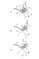
図3は、リップ部1aのリップ下流側面12が周面10a(塗工面)側に傾斜し、塗工ヘッダ1中心線Cとなす角度(リップ下流側面角度)αを変えて塗工した試験結果の例であり、塗工状態図である。
The center line C of the coating header 1 is made substantially perpendicular to the peripheral surface 10a of the cylindrical coating material 10 so that the lip 1a is brought close to the coating header 1, and the cylindrical coating material 10 is rotated around its axis O. The material liquid a was applied on the peripheral surface 10a while the basic test conditions were as follows.
・ Material liquid (volatile ink): Viscosity ≦ 4 mPa · s
・ Coating material: Silicon blanket ・ Coating speed: 0.03 m / s, 0.05 m / s
-Coating film thickness: 10-20 μm
-Material of header and lip portion: SCM material Fig. 3 shows an angle formed by the lip downstream side surface 12 of the lip portion 1a being inclined toward the peripheral surface 10a (coating surface) side and the coating header 1 center line C (lip downstream side surface angle) ) It is an example of a test result applied by changing α, and is a coating state diagram.

(リップ下流側面角度α=0度の場合) 図3(a)に示すように、リップ下流側面12が塗工ヘッダ1中心線Cに対して0°で、リップ端面に対して直角でシャープエッジとなるため、リップ上流側面11への液拡張濡れが抑制される。またリップ部1a下流側のビード位置が安定する。そのため安定した液ビード4が得られている。   (When the lip downstream side surface angle α = 0 °) As shown in FIG. 3A, the lip downstream side surface 12 is 0 ° with respect to the coating header 1 center line C, and is sharp with a right angle to the lip end surface. Therefore, the liquid expansion wetting to the lip upstream side surface 11 is suppressed. Further, the bead position on the downstream side of the lip 1a is stabilized. Therefore, a stable liquid bead 4 is obtained.

(リップ下流側面角度α=12度の場合) 図3(b)に示すように、この場合もリップ下流側面12が塗工ヘッダ1中心線Cに対して12度と、シャープエッジに近い形状のため、リップ上流側面11への液拡張濡れが抑制されており、良好で安定した液ビードが得られている。   (In the case of the lip downstream side surface angle α = 12 degrees) As shown in FIG. 3B, the lip downstream side surface 12 also has a shape close to a sharp edge, 12 degrees with respect to the center line C of the coating header 1 in this case. Therefore, the liquid expansion wetting to the lip upstream side surface 11 is suppressed, and a good and stable liquid bead is obtained.

(リップ下流側面角度α=30度の場合) 図3(c)に示すように、リップ下流側面12を塗工ヘッダ1中心線Cに対し30度と大きく、リップ下流側面角度αが大きくなると、液がリップ下流側面12に材料液aが付着しやすくなる。この付着した材料液aは揮発性インキのため、すぐ硬化してリップ部1aに固着する。この固着した材料液aに、新たに塗工した材料液aが付着し、図示のようにリップ部1a下流側のビード位置5が乱れてくる。その結果として塗工された液ビード4は不均一で安定性のない液ビードとなる。   (In the case of the lip downstream side surface angle α = 30 degrees) As shown in FIG. 3 (c), when the lip downstream side surface 12 is larger than the coating header 1 center line C by 30 degrees, and the lip downstream side surface angle α is increased, The liquid easily adheres to the material liquid a on the lip downstream side surface 12. Since the adhered material liquid a is volatile ink, it immediately cures and adheres to the lip 1a. The newly applied material liquid a adheres to the fixed material liquid a, and the bead position 5 on the downstream side of the lip 1a is disturbed as shown in the figure. As a result, the coated liquid beads 4 are non-uniform and unstable liquid beads.

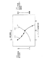
以上の試験結果をまとめたグラフを図4に示す。横軸はリップ下流側面角度αを示し、左縦軸は「(イ)材料液固着防止効果」(液ビード安定性)、右縦軸は「(ロ)リップ先端形状加工性の難易度」を示す。リップ先端形状の機械加工性の難易度は、リップ部1aの先端は非常に小さく、また硬い材料を使用するが、実際の装置に利用するためには塗工方向に対し幅方向に精度良く、均一に加工する必要があり、実際にはこの加工が困難な事から考慮したものである。   A graph summarizing the above test results is shown in FIG. The horizontal axis indicates the lip downstream side surface angle α, the left vertical axis indicates “(b) material liquid adhesion prevention effect” (liquid bead stability), and the right vertical axis indicates “(b) difficulty level of lip tip shape workability”. Show. The difficulty of the machinability of the lip tip shape is that the tip of the lip 1a is very small and uses a hard material, but in order to use it in an actual device, it is accurate in the width direction with respect to the coating direction. This is due to the fact that it is necessary to perform uniform processing, and this processing is actually difficult.

図4に示すように、(イ)材料液固着防止効果(液ビード安定性)は、リップ下流側面角度αが0°で、リップ下流側面12がシャープエッジ(直角)になるほど良いビードが得られが、リップ下流側面角度αが30°の場合は、材料液aの固着が発生し、適していない。またリップ部1aの機械加工の難易度は、シャープエッジになるほど困難になり、リップ下流側面角度αが大きくなるほど容易になる。   As shown in FIG. 4, (a) the material liquid sticking prevention effect (liquid bead stability) is such that a better bead is obtained when the lip downstream side surface angle α is 0 ° and the lip downstream side surface 12 has a sharp edge (right angle). However, when the lip downstream side surface angle α is 30 °, the material liquid a is fixed, which is not suitable. Further, the difficulty of machining the lip portion 1a becomes more difficult as the edge becomes sharper, and becomes easier as the lip downstream side surface angle α increases.

そこで、実際に機械加工でき、また良好な液ビードが得られる適正領域としては、リップ下流側面角度α=0〜20度、機械加工上から、より望ましくはα=5〜20度の範囲である。その場合、塗工する材料液aが揮発性インキ液の場合でもインキ液がリップ先端に固着しないので、良好で安定した塗工が可能となる。   Therefore, an appropriate region where the actual machining can be performed and a good liquid bead can be obtained is a lip downstream side surface angle α = 0 to 20 °, and more preferably α = 5 to 20 ° from the viewpoint of machining. . In that case, even when the material liquid a to be applied is a volatile ink liquid, the ink liquid does not adhere to the tip of the lip, so that a good and stable coating can be achieved.

(2)塗工ヘッダの配置について:
本発明者の研究により、塗工ヘッダ1により塗工される被塗工材の傾斜角度、すなわち塗工面角度θが、材料液(塗工液)aの厚み等、塗工状態の安定化に影響することが判明し、研究・試験の結果、塗工面角度θの最適化につき(また、塗工ヘッダ1は通常、塗工面に略垂直に配置されるから、塗工ヘッダ1の配置の最適化につき)、下記のことを見出した。
(2) About the layout of the coating header:
According to the inventor's research, the inclination angle of the material to be coated applied by the coating header 1, that is, the coating surface angle θ is used to stabilize the coating state such as the thickness of the material liquid (coating liquid) a. As a result of research and testing, it was found that the coating surface angle θ was optimized (and the coating header 1 is usually disposed substantially perpendicular to the coating surface, so that the optimal placement of the coating header 1 is The following was found.

図5に基づき、塗工ヘッダ1の最適配置を決定するための試験を説明する。図5は、塗工面角度θ最適化のための試験におけるシリンダ状被塗工材10に対する塗工ヘッダの配置図であり、シリンダ状被塗工材10の周面10aに対して塗工ヘッダ1の中心線Cを垂直に向け、すなわちシリンダ状被塗工材10の軸芯Oに向けて、リップ部1aを近接させ、リンダ状被塗工材10を回転させつつ、材料液aを周面10a上に塗工したもので、基本的な試験条件は次の通りである。
・材料液(揮発性インキ):粘度≦4mPa・s
・被塗工材:シリコンブランケット
・塗工速度:0.03m/s、0.05m/s
・塗工被膜厚さ:10〜20μm
・ヘッダ、リップ部の材料:SCM材
塗工ヘッダ1は、シリンダ状被塗工材10の真下の位置で上向き配置の場合、すなわち、シリンダ状被塗工材10の塗工面角度θ=0°、鉛直方向Yに対する塗工ヘッダ1の方向Cの角度θ=0°の位置から、シリンダ状被塗工材10の真横の位置で水平向き配置の場合、すなわち、塗工面角度θ=90°、周面10a上の塗工ヘッダ1の位置の鉛直方向Yに対する角度θ=90°の位置まで、塗工ヘッダ1の位置を変えて、シリンダ状被塗工材10に塗工される材料液aの液ビードの塗工状況を試験した。
Based on FIG. 5, the test for determining the optimal arrangement | positioning of the coating header 1 is demonstrated. FIG. 5 is a layout diagram of the coating header with respect to the cylindrical coating material 10 in the test for optimizing the coating surface angle θ, and the coating header 1 with respect to the peripheral surface 10 a of the cylindrical coating material 10. The center line C is oriented vertically, that is, toward the axis O of the cylindrical coating material 10, the lip portion 1 a is brought close to it, and the binder-shaped coating material 10 is rotated, while the material liquid a is peripheral. The basic test conditions are as follows.
・ Material liquid (volatile ink): Viscosity ≦ 4 mPa · s
・ Coating material: Silicon blanket ・ Coating speed: 0.03 m / s, 0.05 m / s
-Coating film thickness: 10-20 μm
-Header and lip material: SCM material When the coating header 1 is arranged upward at a position directly below the cylindrical coating material 10, that is, the coating surface angle θ = 0 ° of the cylindrical coating material 10. From the position of the angle θ = 0 ° in the direction C of the coating header 1 with respect to the vertical direction Y, in the case of a horizontal orientation at a position just beside the cylindrical coated material 10, that is, the coating surface angle θ = 90 °, The material liquid a applied to the cylindrical coated material 10 by changing the position of the coating header 1 until the position of the coating header 1 on the peripheral surface 10a is at an angle θ = 90 ° with respect to the vertical direction Y. The coating condition of the liquid beads was tested.

塗工ヘッダ1から供給された材料液aがシリンダ状被塗工材10の周面10a(塗工面)に塗工される時、材料液aには、重量Gで落下する力と、シリンダ状被塗工材10の移動により材料液aの粘度に基づく塗工面に沿う方向(接線方向)の液引出し力f(以下、「塗工面方向液引出し力f」という)が作用する。   When the material liquid a supplied from the coating header 1 is applied to the peripheral surface 10a (coating surface) of the cylindrical coating material 10, the material liquid a has a force that drops with a weight G and a cylindrical shape. Due to the movement of the material to be coated 10, a liquid drawing force f (hereinafter referred to as “coating surface direction liquid drawing force f”) in the direction along the coating surface (tangential direction) based on the viscosity of the material liquid a acts.

この試験は、上記の重量Gと、塗工面方向液引出し力fの鉛直方向成分F(以下、「鉛直方向液引出し力F」という)との関係が、被塗工材に塗工される液ビードの安定性を左右すると着目したものである。   In this test, a liquid in which the relationship between the weight G and the vertical component F of the liquid drawing force f in the coating surface (hereinafter referred to as “vertical liquid drawing force F”) is applied to the material to be coated. It focuses on the stability of the bead.

図5に示すように、F=f・sinθであるから、θ=0°でF=f・sin0°=0、θ=90°でF=f・sin90°=fとなり、塗工状況の試験結果の代表例を、下記のように図6〜図8に示す。   As shown in FIG. 5, since F = f · sin θ, F = f · sin 0 ° = 0 at θ = 0 °, and F = f · sin 90 ° = f at θ = 90 °. Representative examples of the results are shown in FIGS. 6 to 8 as follows.

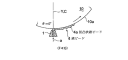
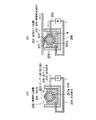
(塗工ヘッダ1をシリンダ状被塗工材10の軸芯真下に上向きに配置した場合) 図6(及び図5)に示すように、塗工ヘッダ1に相対する周面10aの接線方向の水平方向Xに対する角度が塗工面角度θであり、塗工ヘッダ1の周面10a上の位置の鉛直方向Yに対する角度もθ=0°である。従って、塗工ヘッダ1をシリンダ状被塗工材10に対し真下から塗工する場合は、鉛直方向液引出し力F=sin0°=0 であり、一方、重量Gは大きく作用し(F≪G)、しかも材料液供給速度が減少する方向に作用するので、シリンダ状被塗工材10に塗工された液ビード4は、幅方向にも、進行方向にも均一性がなく、図示のように凹凸状液ビード4aとなりやすい。   (When the coating header 1 is arranged upward directly below the axial center of the cylindrical coating material 10) As shown in FIG. 6 (and FIG. 5), the tangential direction of the peripheral surface 10a facing the coating header 1 The angle with respect to the horizontal direction X is the coating surface angle θ, and the angle with respect to the vertical direction Y of the position on the peripheral surface 10a of the coating header 1 is also θ = 0 °. Accordingly, when the coating header 1 is applied to the cylindrical coating material 10 from directly below, the vertical direction liquid drawing force F = sin 0 ° = 0, while the weight G acts greatly (F << G In addition, since it acts in the direction in which the material liquid supply speed decreases, the liquid bead 4 applied to the cylindrical coated material 10 is not uniform in both the width direction and the traveling direction, as shown in the figure. It is easy to become uneven liquid beads 4a.

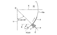
(塗工ヘッダ1をシリンダ状被塗工材10の周面上、真下の位置から鉛直方向Yに対してθ回った位置に配置した場合) 図7(及び図5)に示すように、塗工ヘッダ1に相対する周面10aの接線方向の水平方向Xに対する角度が塗工面角度θであり、塗工ヘッダ1の周面10a上の位置の鉛直方向Yに対する角度はθである。   (When the coating header 1 is arranged on the circumferential surface of the cylindrical coating material 10 at a position rotated θ from the position directly below the vertical direction Y) As shown in FIG. 7 (and FIG. 5) The angle with respect to the horizontal direction X in the tangential direction of the peripheral surface 10a facing the work header 1 is the coating surface angle θ, and the angle with respect to the vertical direction Y of the position on the peripheral surface 10a of the coating header 1 is θ.

塗工面角度θ=20°〜65°の場合は重力Gと塗工面方向液引出し力fの鉛直方向成分が発生し、鉛直方向液引出し力F=fsinθ が重量Gとほぼ同等かやや大の力(F≧G)としやすいので、液だれも発生せず、均一なビードが塗布できる。   When the coating surface angle θ = 20 ° to 65 °, vertical components of the gravity G and the liquid drawing force f in the coating surface are generated, and the vertical liquid drawing force F = fsinθ is almost equal to the weight G or slightly larger force. Since it is easy to set it as (F> = G), a dripping does not generate | occur | produce and a uniform bead can be apply | coated.

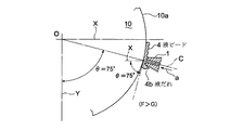
(塗工ヘッダ1をシリンダ状被塗工材10の真横に近い、真下から75°の位置に配置した場合) 図8(及び図5)に示すように、塗工ヘッダ1に相対する周面10aの接線方向の水平方向Xに対する角度が塗工面角度θ=75°であり、塗工ヘッダ1の周面10a上の位置の鉛直方向Yに対する角度もθ=75°である。この場合は、鉛直方向液引出し力F=fsin75°は、塗工面角度θ=20°〜65°の場合よりもさらに大きくなり、F>Gとなりやすいので、液ビード4の形成はさらに安定する。   (When the coating header 1 is arranged at a position close to the side of the cylinder-shaped coated material 10 and at a position of 75 ° from directly below) As shown in FIG. 8 (and FIG. 5), the circumferential surface facing the coating header 1 The angle of the tangential direction of 10a with respect to the horizontal direction X is the coating surface angle θ = 75 °, and the angle of the position on the peripheral surface 10a of the coating header 1 with respect to the vertical direction Y is also θ = 75 °. In this case, the vertical liquid drawing force F = fsin 75 ° is further larger than that in the case of the coating surface angle θ = 20 ° to 65 °, and F> G tends to be satisfied, so that the formation of the liquid bead 4 is further stabilized.

すなわち、上記のように水平位置に近づき、塗工ヘッダ1の取り付け位置の塗工面角度θ、すなわち周面10a上の角度θが大きくなり90°に近づき、塗工面角度θが90°に近づくほど、鉛直方向液引出し力Fが大きくなり、液ビード4が安定する。   That is, as it approaches the horizontal position as described above, the coating surface angle θ at the mounting position of the coating header 1, that is, the angle θ on the peripheral surface 10 a increases and approaches 90 °, and the coating surface angle θ approaches 90 °. The liquid withdrawal force F in the vertical direction is increased, and the liquid bead 4 is stabilized.

しかし、実際の運用においては、塗工面角度θが大きくなるにつれ、塗工ヘッダ1の中心線方向Cが鉛直方向Y上向きから水平方向Xへと傾くため、塗工開始前に液だれ4bが発生し、リップ部1a(塗工ヘッダ1の先端部)の裏側に回り込み、上流側のビード位置(液溜まり)が乱れる。そのため液ビード4も不均一な塗工状態となってくる。そのため、塗工面角度θが45°を越えると膜厚誤差が増大する。   However, in actual operation, as the coating surface angle θ increases, the center line direction C of the coating header 1 tilts from the vertical direction Y upward to the horizontal direction X, and therefore, dripping 4b occurs before the start of coating. Then, the lip portion 1a (the tip portion of the coating header 1) goes around to the back side, and the upstream bead position (liquid pool) is disturbed. Therefore, the liquid bead 4 is also in a non-uniform coating state. Therefore, when the coating surface angle θ exceeds 45 °, the film thickness error increases.

ちなみに、塗工ヘッダ1をシリンダ状被塗工材10に対して下向きに配置すると、重量Gが大きく作用し、しかも材料液供給速度が増大する方向に作用するので、液だれが発生し易く、安定した塗工が困難となり、通常用いられない。   By the way, when the coating header 1 is disposed downward with respect to the cylindrical coating material 10, the weight G acts greatly, and the material liquid supply speed increases, so that dripping easily occurs. Stable coating becomes difficult and is not usually used.

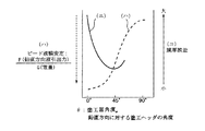
図9は、以上の試験結果をまとめたグラフであり、図9において、横軸は水平面方向Xに対する「塗工面角度θ」〔シリンダ状被塗工材10の場合は、塗工ヘッダ1の位置の鉛直方向に対する周面10a上の角度であり、塗工ヘッダ中心線Cを塗工面方向(周面10a接線方向)に対して垂直に配置した場合は、鉛直方向Yに対する塗工ヘッダの角度〕、縦軸(ハ)は塗工した液ビードのビード液膜の安定性を示し、縦軸(ニ)は液ビードの膜厚誤差を示す。   FIG. 9 is a graph summarizing the above test results. In FIG. 9, the horizontal axis represents “coating surface angle θ” with respect to the horizontal plane direction X [in the case of the cylindrical coating material 10, the position of the coating header 1. Of the coating header relative to the vertical direction Y when the coating header center line C is arranged perpendicular to the coating surface direction (tangential direction of the circumferential surface 10a). The vertical axis (c) shows the stability of the bead liquid film of the coated liquid bead, and the vertical axis (d) shows the film thickness error of the liquid bead.

また、図9に示す結果の評価を、〔表1〕にまとめて示す。   Moreover, evaluation of the result shown in FIG. 9 is collectively shown in [Table 1].

Figure 2005296797
この結果より、比較的良好な液ビード4が得られる塗工面角度θは、θ=25〜65°の領域、また望ましくは、θ=40〜50度の領域であることが判明した。すなわち、塗工ヘッダ1をシリンダ状被塗工材10の真下からθ=25〜65°、望ましくは、θ=40〜50°回った位置に取付け、鉛直方向液引出し力Fを重量G以上(F≧G)とし、上流側のビード位置を固定した方が良い。
Figure 2005296797
From this result, it was found that the coating surface angle θ at which a relatively good liquid bead 4 is obtained is in the region of θ = 25 to 65 °, and preferably in the region of θ = 40 to 50 degrees. That is, the coating header 1 is mounted at a position θ = 25 to 65 °, preferably θ = 40 to 50 °, directly below the cylindrical coating material 10, and the vertical liquid drawing force F is more than the weight G ( F ≧ G) and the upstream bead position should be fixed.

(3)以上の試験結果に示されることから、上記実施例は以下の作用効果を奏すると言える。   (3) From the above test results, it can be said that the above example has the following effects.

(シリンダ状被塗工材10の場合:実施例1) 上記したように、リップ下流側面12をリップ下流側面角度α=0〜20°、さらに好ましくはα=5〜20°の範囲となるように加工したリップ部1aを設けた塗工ヘッダ1とする。また、塗工ヘッダ1の取付位置は、塗工面角度θ=25〜65°となるように、塗工ヘッダ1の位置をシリンダ状被塗工材10に対し真下からの周面10a上の角度θ=25〜65°の領域で設置し、鉛直方向液引出し力Fを重力G以上(F≧G)とし、上流側のビード位置を固定した方が良い。   (In the case of the cylindrical coating material 10: Example 1) As described above, the lip downstream side surface 12 has a lip downstream side surface angle α = 0 to 20 °, and more preferably α = 5 to 20 °. It is set as the coating header 1 which provided the lip | rip part 1a processed into. Moreover, the attachment position of the coating header 1 is an angle on the peripheral surface 10a from directly below the position of the coating header 1 with respect to the cylindrical coating material 10 so that the coating surface angle θ = 25 to 65 °. It is better to install in the region of θ = 25 to 65 °, set the vertical liquid drawing force F to gravity G or more (F ≧ G), and fix the upstream bead position.

これにより実施例1においては、材料液固着が発生しない条件となり、シリンダ状被塗工材10に均一の厚みで、安定したビード形状で材料液aを塗工でき、リングパターンの問題を回避し塗工速度向上が可能となる。特に、材料液aの固着が生じやすかった揮発性インキを材料液aとして塗工する場合、その作用効果が顕著である。   Thus, in Example 1, the material liquid does not stick, and the material liquid a can be applied to the cylindrical coated material 10 with a uniform thickness and a stable bead shape, thereby avoiding the ring pattern problem. The coating speed can be improved. In particular, when a volatile ink that is likely to adhere to the material liquid a is applied as the material liquid a, the effect is remarkable.

(平板状被塗工材20の場合:実施例2、実施例3) 平板状被塗工材20は、ハンドリングの都合上、水平に配置し、水平方向に移動させつつ塗工する場合が多いが、その場合、実施例1のように平板状被塗工材20下面(塗工面)に対して垂直で上向きに塗工ヘッダ1を配置し、リップ下流側面角度α=0〜20°、さらに好ましくはα=5〜20°の範囲となるように加工したリップ部1aを設けた塗工ヘッダ1とする。これにより実施例2においては、材料液固着が発生しない条件となり、揮発性インキを材料液aとした場合でも、平板状被塗工材20に均一の厚みで、安定したビード形状で材料液aを塗工でき、リングパターンの問題を回避し塗工速度向上が可能となる。   (In the case of the flat coated material 20: Example 2 and Example 3) The flat coated material 20 is often disposed horizontally for the convenience of handling and coated while being moved in the horizontal direction. However, in that case, as in Example 1, the coating header 1 is arranged vertically and upward with respect to the lower surface (coating surface) of the flat plate-shaped material 20 to be coated, and the lip downstream side surface angle α = 0 to 20 °. Preferably, the coating header 1 is provided with a lip portion 1a processed so as to be in a range of α = 5 to 20 °. Thus, in Example 2, the material liquid does not stick, and even when the volatile ink is used as the material liquid a, the material liquid a has a uniform bead shape and a uniform bead shape on the flat coated material 20. The coating speed can be improved by avoiding the ring pattern problem.

平板状被塗工材20の下面(塗工面)と同下面に対する塗工ヘッダ1との関係は、シリンダ状被塗工材10における周面10a(塗工面)と同周面1aに対する塗工ヘッダ1との関係と同様である。そこで実施例3のように、実施例2と同様にリップ下流側面角度α=0〜20°、さら機械加工上に好ましくはα=5〜20°の範囲となるように加工したリップ部1aを設けた塗工ヘッダ1を用い、さらに、平板状被塗工材20を水平方向Xに対してθ傾斜して設置し塗工面角度θとし、その塗工面角度θの方向に移動させつつ、平板状被塗工材20の下面に近接する塗工ヘッダ1によって塗工する場合は、塗工面角度θ=20〜65°に設定すると、実施例1と同様に材料液固着が発生しない条件となり、被塗工材に均一の厚みで、安定したビード形状で材料液aを塗工でき、リングパターンの問題を回避し塗工速度向上が可能となる。特に、材料液aの固着が生じやすかった揮発性インキを材料液aとして塗工する場合、その作用効果が顕著である。   The relationship between the lower surface (coating surface) of the flat coated material 20 and the coating header 1 with respect to the lower surface is as follows: the peripheral surface 10a (coating surface) of the cylindrical coated material 10 and the coating header with respect to the same peripheral surface 1a. It is the same as the relationship with 1. Accordingly, as in the third embodiment, the lip portion 1a processed so that the lip downstream side surface angle α = 0 to 20 °, and more preferably in the range of α = 5 to 20 °, as in the second embodiment. Using the coating header 1 provided, the flat coated material 20 is installed with an inclination of θ with respect to the horizontal direction X to a coating surface angle θ, and is moved in the direction of the coating surface angle θ. In the case of coating with the coating header 1 close to the lower surface of the material to be coated 20, when the coating surface angle θ is set to 20 to 65 °, it becomes a condition that the material liquid is not fixed as in Example 1, The material liquid a can be applied to the material to be coated in a uniform bead shape with a uniform thickness, avoiding a ring pattern problem and improving the coating speed. In particular, when a volatile ink that is likely to adhere to the material liquid a is applied as the material liquid a, the effect is remarkable.

なお、その場合、平板状被塗工材20の下面に対し塗工ヘッダ1の中心軸方向Cを垂直に配向させて設置すれば、鉛直方向Yに対して塗工ヘッダ中心線Cのなす角度もθである。   In this case, if the central axis direction C of the coating header 1 is oriented perpendicularly to the lower surface of the flat plate-shaped workpiece 20, the angle formed by the coating header center line C with respect to the vertical direction Y is set. Is also θ.

従って、上記実施例1から実施例3のいずれかの塗工ヘッダを備えた薄膜形成装置は、基材または薄膜塗工ローラ等の被塗工材に、均一の厚みで、安定した液ビード形状で、材料液を塗工でき、リングパターンの問題を回避し塗工精度、塗工速度向上が可能な薄膜形成装置となる。   Therefore, the thin film forming apparatus including the coating header according to any of the first to third embodiments has a uniform liquid bead shape with a uniform thickness on a substrate or a material to be coated such as a thin film coating roller. Thus, the material liquid can be applied, and a thin film forming apparatus capable of improving the coating accuracy and the coating speed by avoiding the ring pattern problem.

なお、本実施例の薄膜形成装置は、図12に図示の薄膜形成装置100に限られず、図12を参照して説明すれば、図示とは逆に、薄膜塗工ローラ104を位置固定とし、基材110を移動させるものでもよく、また、基材110を塗工ヘッダ101と接触するような高さ位置に設定するとともに、その高さ位置において基材110を図中で左右に移動させる移動装置を設け、薄膜塗工ローラ104無しで塗工ヘッダ101から基材110へ直接塗工を行うものでもよく、基材110が平板状のものでなくシリンダ状のものの場合は、塗工ヘッダ101と接触した状態で回転させる回転駆動装置を設けたものでもよい。   Note that the thin film forming apparatus of the present embodiment is not limited to the thin film forming apparatus 100 illustrated in FIG. 12, and will be described with reference to FIG. 12. The base 110 may be moved, and the base 110 is set to a height position in contact with the coating header 101, and the base 110 is moved left and right in the drawing at the height. An apparatus may be provided to perform coating directly from the coating header 101 to the substrate 110 without the thin film coating roller 104. When the substrate 110 is not flat but cylindrical, the coating header 101 It may be provided with a rotation drive device that rotates in a state of contact with.

また、薄膜形成装置100は、塗工ヘッダ101が1基のものではなく、材料液の色等の種類によって塗工ヘッダ101を複数基備え、合わせて薄膜塗工ローラ104も複数基備えたものでもよい。   Further, the thin film forming apparatus 100 is not provided with a single coating header 101, but includes a plurality of coating headers 101 depending on the type of material liquid and the like, and a plurality of thin film coating rollers 104. But you can.

以上述べたように、各実施例の塗工ヘッダ1は、一般的に薄膜形成装置用の塗工ヘッダとして用いられるものであるが、特に薄膜形成装置の一つとしての反転印刷装置において、その塗工ヘッダとして、有効に実施し得るものとなる。   As described above, the coating header 1 of each embodiment is generally used as a coating header for a thin film forming apparatus. In particular, in a reverse printing apparatus as one of the thin film forming apparatuses, As a coating header, it can be effectively implemented.

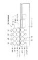
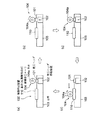
一般的にカラーフィルタ等を形成する方法としては、印刷法、フォトリソ法等の方法が知られているが、印刷法においては反転印刷装置を用いることが有効であり、以下、一般的な反転印刷装置と、反転印刷装置による印刷法で薄膜(カラーフィルタ等)を形成する原理について図10、図11により説明する。図10は一般的な反転印刷装置の概要構成図、図11(a)〜(c)は一般的な反転印刷装置の動作と原理の説明図である。   In general, methods such as a printing method and a photolithographic method are known as methods for forming a color filter, etc., but it is effective to use a reversal printing apparatus in the printing method. The principle of forming a thin film (color filter or the like) by a printing method using an apparatus and a reverse printing apparatus will be described with reference to FIGS. FIG. 10 is a schematic configuration diagram of a general reverse printing apparatus, and FIGS. 11A to 11C are explanatory views of the operation and principle of the general reverse printing apparatus.

図10に示すように反転印刷装置50の固定フレーム51には、シリコンシート52を表面に貼り付けた塗布胴53、塗布胴53表面に接して材料液として樹脂(インキ)a′を塗布(塗工)する塗布装置54を1ユニットとし、各色分、すなわち、ブラックマトリクス、レッド、グリーン、ブルーの4ユニット(ブラックマトリクス用ユニットU1、レッド用ユニットU2、グリーン用ユニットU3、ブルー用ユニットU4)分と基板シート55を設置する印刷定盤56が設けてある。また、固定フレーム51上には移動する可動フレーム57があり、可動フレーム57にはシリコンブランケット58が巻き付けてあるブランケット胴59、同ブランケット胴59と接して、凸版60を表面に取り付けた回転する版胴61を1ユニットとし、固定フレーム51の塗布胴53に対応して設けてある。   As shown in FIG. 10, the fixed frame 51 of the reverse printing apparatus 50 is coated with a coating cylinder 53 with a silicon sheet 52 attached to the surface, and a resin (ink) a ′ is applied (coated) as a material liquid in contact with the surface of the coating cylinder 53. The coating device 54 to be processed is one unit, and for each color, that is, four units of black matrix, red, green, and blue (black matrix unit U1, red unit U2, green unit U3, blue unit U4) And a printing surface plate 56 on which the substrate sheet 55 is installed. Further, there is a movable frame 57 that moves on the fixed frame 51. The movable frame 57 is in contact with a blanket cylinder 59 around which a silicon blanket 58 is wound, and a rotating plate with a relief 60 attached to the surface. The cylinder 61 is a unit, and is provided corresponding to the application cylinder 53 of the fixed frame 51.

図11は、図10に示す反転印刷装置50の動作及び原理を示す図である。塗布装置54により塗布胴53上に貼り付けてあるシリコンシート52上に着色された樹脂(インキ)a′を塗布し、この樹脂a′をブランケット胴59、上のシリコンブランケット58に転写する(a)。次に版胴61上に樹脂版を露光、現像し、所定の形状に凸部を形成した凸版60を取り付け、凸版60を押圧しブランケット58上の塗布面から凸部分の樹脂a′を除去する(b)。ブランケット58面上の残りの樹脂a′を可動フレームの移動により印刷定盤上の基板シート55上に転写する(c)。この原理によって、ブラックマトリクス、レッド、グリーン、ブルーにつき可動フレームが往復することにより基板シート55にブラックマトリクスとレッド(R)、グリーン(G)、ブルー(B)の画素のカラーフィルタ層を形成することができる。   FIG. 11 is a diagram showing the operation and principle of the reverse printing apparatus 50 shown in FIG. A colored resin (ink) a ′ is applied on the silicon sheet 52 pasted on the coating cylinder 53 by the coating device 54, and this resin a ′ is transferred to the blanket cylinder 59 and the upper silicon blanket 58 (a). ). Next, the resin plate is exposed and developed on the plate cylinder 61, and a relief plate 60 having projections formed in a predetermined shape is attached, and the relief plate 60 is pressed to remove the resin a 'at the convex portion from the coating surface on the blanket 58. (B). The remaining resin a 'on the blanket 58 surface is transferred onto the substrate sheet 55 on the printing surface plate by moving the movable frame (c). Based on this principle, the black matrix and the color filter layers of the red (R), green (G), and blue (B) pixels are formed on the substrate sheet 55 by moving the movable frame back and forth for black matrix, red, green, and blue. be able to.

以上のような反転印刷装置50において、塗布胴53は、上記実施例における「シリンダ状被塗工材10」に相当するので、塗布装置54に、上記実施例の「塗工ヘッダ1」を適用することで、上述の実施例1の塗工ヘッダ1の作用効果を反転印刷装置50において奏することができる。(なお、図10、図11は一般的な反転印刷装置を示すものであるので、図中の塗布装置54は、本発明の実施例の塗工ヘッダ1を明示するものではない。)
すなわち、上記実施例1の塗工ヘッダ1を備えた反転印刷装置50は、被塗工材となる塗布胴53に、均一の厚みで、安定した液ビード形状で、材料液としての樹脂(インキ)a′を塗布(塗工)でき、リングパターン等の問題を回避し、塗工精度、塗工速度向上が可能な反転印刷装置となる
以上、本発明を図示の実施例について説明したが、本発明は上記の実施例に限定されず、本発明の範囲内でその具体的構造に種々の変更を加えてよいことはいうまでもない。
In the reverse printing apparatus 50 as described above, the coating cylinder 53 corresponds to the “cylindrical coated material 10” in the above embodiment, and thus the “coating header 1” in the above embodiment is applied to the coating apparatus 54. By doing so, the effect of the coating header 1 of the above-described first embodiment can be exhibited in the reverse printing apparatus 50. (In addition, since FIG. 10, FIG. 11 shows a general reversal printing apparatus, the coating device 54 in a figure does not clearly show the coating header 1 of the Example of this invention.)
That is, the reversal printing apparatus 50 provided with the coating header 1 of Example 1 described above has a uniform thickness, a stable liquid bead shape, and a resin (ink) as a material liquid on the coating cylinder 53 to be coated. ) A 'can be applied (coating), avoiding problems such as ring patterns, and the reverse printing apparatus capable of improving the coating accuracy and coating speed, the present invention has been described with respect to the illustrated embodiment, It goes without saying that the present invention is not limited to the above-described embodiments, and various modifications may be made to the specific structure within the scope of the present invention.

本発明の実施例1に係る塗工ヘッダの説明図であり、(a)はシリンダ状被塗工材に対する本実施例の塗工ヘッダの配置図、(b)は本実施例の塗工ヘッダの拡大断面図である。It is explanatory drawing of the coating header which concerns on Example 1 of this invention, (a) is the arrangement | positioning figure of the coating header of a present Example with respect to a cylindrical coating material, (b) is a coating header of a present Example. FIG. (a)は、本発明の実施例2に係る塗工ヘッダの説明図であり、平板状被塗工材に対する本実施例の塗工ヘッダの配置図、(b)は、本発明の実施例3に係る塗工ヘッダの説明図であり、平板状被塗工材に対する本実施例の塗工ヘッダの配置図である。(A) is explanatory drawing of the coating header which concerns on Example 2 of this invention, the arrangement | positioning figure of the coating header of this Example with respect to a plate-shaped coating material, (b) is an Example of this invention 3 is an explanatory diagram of a coating header according to FIG. 3, and is a layout diagram of the coating header of the present embodiment with respect to a flat plate-like material to be coated. リップ下流側面角度αを変えて塗工した試験結果の例を示す塗工状態図である。It is a coating state figure which shows the example of the test result coated by changing lip downstream side surface angle (alpha). リップ下流側面角度αと、(イ)材料液固着防止効果および(ロ)リップ先端形状加工性の難易度との関係の試験結果を表すグラフである。It is a graph showing the test result of the relationship between lip downstream side surface angle (alpha), (b) difficulty of material liquid sticking prevention effect, and (b) lip tip shape workability. 塗工面角度θ最適化のための試験におけるシリンダ状被塗工材に対する塗工ヘッダの配置図である。It is a layout view of a coating header for a cylindrical coated material in a test for optimizing the coating surface angle θ. 塗工ヘッダをシリンダ状被塗工材の軸芯真下に上向きに配置した場合の、塗工状況の説明図である。It is explanatory drawing of the coating condition at the time of arrange | positioning a coating header upwards directly under the axial center of a cylindrical coating material. 塗工ヘッダをシリンダ状被塗工材の軸芯真下の位置から鉛直方向Yに対してθ回った位置に配置した場合の、塗工状況の説明図である。It is explanatory drawing of the coating condition at the time of arrange | positioning the coating header in the position which turned (theta) with respect to the vertical direction Y from the position right under the axial center of a cylindrical coating material. 塗工ヘッダをシリンダ状被塗工材の真横に近い、軸芯真下から75°の位置に配置した場合の、塗工状況の説明図である。It is explanatory drawing of the coating condition at the time of arrange | positioning a coating header at the position of 75 degrees from right under an axial center near the cylinder-shaped to-be-coated material. 水平面方向Xに対する塗工面角度θと、(ハ)塗工した液ビードのビード液膜の安定性および(ニ)液ビードの膜厚誤差との関係の試験結果を表すグラフである。It is a graph showing the test result of the relationship between the coating surface angle (theta) with respect to the horizontal surface direction X, (c) stability of the bead liquid film of the liquid bead applied, and (d) film thickness error of the liquid bead. 一般的な反転印刷装置の概要構成図である。It is a schematic block diagram of a general reverse printing apparatus. (a)から(c)は、一般的な反転印刷装置の動作と原理の説明図である。(A) to (c) are explanatory views of the operation and principle of a general reverse printing apparatus. 薄膜形成装置の一般的な例の概要構成図である。It is a schematic block diagram of the general example of a thin film forming apparatus. 従来の表面張力利用型の塗工ヘッダを用いた薄膜形成装置の一例の模式的な要部側断面図である。It is a typical principal part sectional side view of an example of the thin film formation apparatus using the conventional surface tension utilization type coating header. 従来の毛細管現象利用型の塗工ヘッダを用いた薄膜形成装置の一例の模式的な要部側断面図である。It is a typical principal part sectional side view of an example of the thin film forming apparatus using the conventional capillary phenomenon utilization type coating header. 従来の表面張力利用型の塗工ヘッダ(円柱体)の問題の説明図であり、(a)は基材と円柱体とのニップ部の模式的な側面視による断面図であり、(b)は(a)の模式的なA−A矢視断面図である。It is explanatory drawing of the problem of the conventional surface tension utilization type coating header (cylindrical body), (a) is sectional drawing by typical side view of the nip part of a base material and a cylindrical body, (b) FIG. 2A is a schematic cross-sectional view taken along line AA in (a). 従来の毛細管現象利用型の塗工ヘッダの問題の説明図であって、(a)は基材と塗工ヘッダとのニップ部の模式的な側面視による断面図であり、(b)は(a)の模式的なB−B矢視断面図である。It is explanatory drawing of the problem of the conventional capillary phenomenon utilization type coating header, Comprising: (a) is sectional drawing by typical side view of the nip part of a base material and a coating header, (b) is ( It is typical BB arrow sectional drawing of a).

符号の説明Explanation of symbols

1 塗工ヘッダ
1a ニップ部
4 液ビード
4a 凹凸状液ビード
4b 液だれ
10 シリンダ状被塗工材
10a 周面
11 リップ上流側面
12 リップ下流側面
13 スリット
20 平板状被塗工材
50 反転印刷装置
51 固定フレーム
53 塗布胴
54 塗布装置
55 基板シート
57 可動フレーム
59 ブランケット胴
61 版胴
100 薄膜形成装置
101 塗工ヘッダ
102 塗工ヘッダ移動装置
104 薄膜塗工ローラ
104a 周面
θ 塗工面角度
G 重量
F 鉛直方向液引出し力
f 塗工面方向液引出し力
DESCRIPTION OF SYMBOLS 1 Coating header 1a Nip part 4 Liquid bead 4a Irregular-shaped liquid bead 4b Liquid dripping 10 Cylinder-shaped coating material 10a Peripheral surface 11 Lip upstream side surface 12 Lip downstream side surface 13 Slit 20 Flat plate-shaped coating material 50 Reverse printing apparatus 51 Fixed frame 53 Coating cylinder 54 Coating apparatus 55 Substrate sheet 57 Movable frame 59 Blanket cylinder 61 Plate cylinder 100 Thin film forming apparatus 101 Coating header 102 Coating header moving apparatus 104 Thin film coating roller 104a Circumferential surface θ Coating surface angle G Weight F Vertical Directional liquid withdrawal force f Coating surface direction liquid withdrawal force

Claims (8)

液状の材料液を被塗工材の塗工面に塗布し、同塗工面に薄膜を形成する薄膜形成装置用の塗工ヘッダであって、前記材料液を前記被塗工材に供給する前記塗工ヘッダ先端のリップ部におけるリップ下流側面が同塗工ヘッダ中心線に対して0°ないし20°の範囲で前記塗工面側に傾斜して加工されてなることを特徴とする塗工ヘッダ。   A coating header for a thin film forming apparatus that applies a liquid material liquid to a coated surface of a material to be coated and forms a thin film on the coated surface, the coating liquid supplying the material liquid to the material to be coated A coating header characterized in that a lip downstream side surface at a lip portion at a tip of the processing header is processed by being inclined toward the coating surface side in a range of 0 ° to 20 ° with respect to the center line of the coating header. 請求項1に記載の塗工ヘッダにおいて、下方に向き水平方向に対して20°ないし65°の塗工面角度をつけた前記被塗工材の塗工面に、前記リップ部を上向きに近接配置されてなることを特徴とする塗工ヘッダ。   The coating header according to claim 1, wherein the lip portion is arranged close to the coating surface of the material to be coated with a coating surface angle of 20 ° to 65 ° with respect to the horizontal direction facing downward. Coating header characterized by comprising. 請求項1または請求項2に記載の塗工ヘッダにおいて、同塗工ヘッダはその中心方向を、前記リップ部が近接配置された箇所の前記塗工面に垂直に向け配置されてなることを特徴とする塗工ヘッダ。   The coating header according to claim 1 or 2, wherein the coating header is arranged such that a center direction thereof is oriented perpendicularly to the coating surface at a location where the lip portion is disposed close to the coating header. Coating header to be. 請求項1ないし請求項3のいずれかに記載の塗工ヘッダにおいて、前記液状の材料液が揮発性の材料液であることを特徴とする塗工ヘッダ。   The coating header according to any one of claims 1 to 3, wherein the liquid material liquid is a volatile material liquid. 請求項1ないし請求項4のいずれかに記載の塗工ヘッダにおいて、前記被塗工材は平板状被塗工材であり、前記リップ部が近接配置される前記塗工面は同平板状被塗工材の下面であることを特徴とする塗工ヘッダ。   5. The coating header according to claim 1, wherein the material to be coated is a plate-shaped material to be coated, and the coating surface on which the lip portion is disposed in proximity is the same. A coating header, characterized by being the lower surface of the work material. 請求項1ないし請求項4のいずれかに記載の塗工ヘッダにおいて、前記被塗工材はシリンダ状被塗工材であり、前記リップ部が近接配置される塗工面は同シリンダ状被塗工材の下側周面であることを特徴とする塗工ヘッダ。   5. The coating header according to claim 1, wherein the material to be coated is a cylindrical material to be coated, and the coating surface on which the lip portion is disposed in proximity is the same. Coating header characterized by being the lower peripheral surface of the material. 請求項1ないし請求項6のいずれかに記載の塗工ヘッダを備えてなることを特徴とする薄膜形成装置。   A thin film forming apparatus comprising the coating header according to any one of claims 1 to 6. 請求項1ないし請求項4、または請求項6のいずれかに記載の塗工ヘッダを備えてなることを特徴とする反転印刷装置。
A reverse printing apparatus comprising the coating header according to any one of claims 1 to 4 and claim 6.
JP2004116678A 2004-04-12 2004-04-12 Coating header, thin film forming apparatus provided with the same, and reverse printing device Withdrawn JP2005296797A (en)

Priority Applications (1)

Application Number Priority Date Filing Date Title
JP2004116678A JP2005296797A (en) 2004-04-12 2004-04-12 Coating header, thin film forming apparatus provided with the same, and reverse printing device

Applications Claiming Priority (1)

Application Number Priority Date Filing Date Title
JP2004116678A JP2005296797A (en) 2004-04-12 2004-04-12 Coating header, thin film forming apparatus provided with the same, and reverse printing device

Publications (1)

Publication Number Publication Date
JP2005296797A true JP2005296797A (en) 2005-10-27

Family

ID=35328991

Family Applications (1)

Application Number Title Priority Date Filing Date
JP2004116678A Withdrawn JP2005296797A (en) 2004-04-12 2004-04-12 Coating header, thin film forming apparatus provided with the same, and reverse printing device

Country Status (1)

Country Link
JP (1) JP2005296797A (en)

Cited By (4)

* Cited by examiner, † Cited by third party
Publication number Priority date Publication date Assignee Title
DE102013215265A1 (en) 2013-08-02 2015-02-05 Windmöller & Hölscher Kg doser
DE102013215264A1 (en) 2013-08-02 2015-02-05 Windmöller & Hölscher Kg inking
DE102013215267A1 (en) 2013-08-02 2015-02-05 Windmöller & Hölscher Kg doser
US9873937B2 (en) 2009-05-22 2018-01-23 Samsung Display Co., Ltd. Thin film deposition apparatus

Cited By (7)

* Cited by examiner, † Cited by third party
Publication number Priority date Publication date Assignee Title
US9873937B2 (en) 2009-05-22 2018-01-23 Samsung Display Co., Ltd. Thin film deposition apparatus
US10689746B2 (en) 2009-05-22 2020-06-23 Samsung Display Co., Ltd. Thin film deposition apparatus
US11624107B2 (en) 2009-05-22 2023-04-11 Samsung Display Co., Ltd. Thin film deposition apparatus
US11920233B2 (en) 2009-05-22 2024-03-05 Samsung Display Co., Ltd. Thin film deposition apparatus
DE102013215265A1 (en) 2013-08-02 2015-02-05 Windmöller & Hölscher Kg doser
DE102013215264A1 (en) 2013-08-02 2015-02-05 Windmöller & Hölscher Kg inking
DE102013215267A1 (en) 2013-08-02 2015-02-05 Windmöller & Hölscher Kg doser

Similar Documents

Publication Publication Date Title
EP1342508B1 (en) Coating apparatus and coating method
JP2005296797A (en) Coating header, thin film forming apparatus provided with the same, and reverse printing device
JP2010005543A (en) Reverse gravure coating method and device using this method
JP2006281103A (en) Ink supply apparatus, pattern formation method, pattern formation apparatus, color filter formation method, and pattern formation apparatus
US7862864B2 (en) Bar coating method and apparatus
JP2003190870A (en) Method for coating cylindrical body surface and fixation roller formed by the method
JP2006255660A (en) Coating method and coater
JP2007181811A (en) Production method for improving uniformity of quality of coating layer
JPH0677709B2 (en) Transfer device
JP2013166089A (en) Method for applying coating material and coating apparatus
JP2013208826A (en) Thin film printing method and thin film printer
JP4353681B2 (en) Die head for coating
JP3482112B2 (en) Coating method and device
JP2006218433A (en) Method and device of blade coating
JP2009233501A (en) Roll coating method and roll coating apparatus
CN219856474U (en) Liquid supply mechanism and printing device comprising same
JP3881268B2 (en) Coating method and coating apparatus
JP2005058869A (en) Material liquid application header for thin film forming apparatus and thin film forming apparatus
JP2019130859A (en) Doctor blade and printing device
JP5367322B2 (en) Coating equipment
JP2006198475A (en) Blade coating method and disk coating method using this
JP2017021386A (en) Alignment film printing plate and manufacturing method of liquid crystal display device
JP2006205010A (en) Blade coater and printing surface coater for disk
JPH10202156A (en) Roll coater
JP2009028638A (en) Coating method and coating apparatus

Legal Events

Date Code Title Description
A300 Withdrawal of application because of no request for examination

Free format text: JAPANESE INTERMEDIATE CODE: A300

Effective date: 20070703