JP2005296659A - Sewing machine with oil tank and oil-tank immersion body for sewing machine - Google Patents
Sewing machine with oil tank and oil-tank immersion body for sewing machine Download PDFInfo
- Publication number
- JP2005296659A JP2005296659A JP2005112071A JP2005112071A JP2005296659A JP 2005296659 A JP2005296659 A JP 2005296659A JP 2005112071 A JP2005112071 A JP 2005112071A JP 2005112071 A JP2005112071 A JP 2005112071A JP 2005296659 A JP2005296659 A JP 2005296659A
- Authority
- JP
- Japan
- Prior art keywords
- sewing machine
- immersion body
- machine according
- oil
- oil tank
- Prior art date
- Legal status (The legal status is an assumption and is not a legal conclusion. Google has not performed a legal analysis and makes no representation as to the accuracy of the status listed.)
- Pending
Links
- 238000007654 immersion Methods 0.000 title claims abstract description 67
- 238000009958 sewing Methods 0.000 title claims abstract description 42
- 239000012780 transparent material Substances 0.000 claims abstract description 6
- 230000003287 optical effect Effects 0.000 claims description 20
- 238000005461 lubrication Methods 0.000 claims description 2
- 238000012544 monitoring process Methods 0.000 abstract description 9
- 230000001050 lubricating effect Effects 0.000 abstract 1
- 239000003921 oil Substances 0.000 description 85
- 239000011521 glass Substances 0.000 description 3
- 239000010721 machine oil Substances 0.000 description 3
- 230000000694 effects Effects 0.000 description 2
- 238000003780 insertion Methods 0.000 description 2
- 230000037431 insertion Effects 0.000 description 2
- 239000000463 material Substances 0.000 description 2
- 230000003247 decreasing effect Effects 0.000 description 1
- 230000002950 deficient Effects 0.000 description 1
- 238000002347 injection Methods 0.000 description 1
- 239000007924 injection Substances 0.000 description 1
- 238000007689 inspection Methods 0.000 description 1
- 239000000314 lubricant Substances 0.000 description 1
- 239000004033 plastic Substances 0.000 description 1
- 229920003023 plastic Polymers 0.000 description 1
- 229920003229 poly(methyl methacrylate) Polymers 0.000 description 1
- 229920003217 poly(methylsilsesquioxane) Polymers 0.000 description 1
- 239000004926 polymethyl methacrylate Substances 0.000 description 1
- 238000009420 retrofitting Methods 0.000 description 1
- 230000035945 sensitivity Effects 0.000 description 1
- 230000008054 signal transmission Effects 0.000 description 1
- 229920003002 synthetic resin Polymers 0.000 description 1
- 239000000057 synthetic resin Substances 0.000 description 1
Images

Classifications
-
- D—TEXTILES; PAPER
- D05—SEWING; EMBROIDERING; TUFTING
- D05B—SEWING
- D05B71/00—Lubricating or cooling devices
-
- B—PERFORMING OPERATIONS; TRANSPORTING
- B43—WRITING OR DRAWING IMPLEMENTS; BUREAU ACCESSORIES
- B43K—IMPLEMENTS FOR WRITING OR DRAWING
- B43K23/00—Holders or connectors for writing implements; Means for protecting the writing-points
- B43K23/008—Holders comprising finger grips
Landscapes
- Engineering & Computer Science (AREA)
- Mechanical Engineering (AREA)
- Textile Engineering (AREA)
- Sewing Machines And Sewing (AREA)
Abstract
Description
本発明は、請求項1のプレアンブル部分に従うオイルタンク付きミシンに関する。さらに本発明は、請求項14に従うミシンのオイルタンク浸漬体に関する。
The invention relates to a sewing machine with an oil tank according to the preamble part of claim 1. Furthermore, the present invention relates to an oil tank immersion body of a sewing machine according to
ミシンは、潤滑剤、具体的にはオイルを供給しなければならない多数のベアリングを有する。このために、ミシンは、管路によって潤滑点に接続する少なくとも1つのオイルタンクを有する。主に用いられる管路は芯管路−すなわちホースに芯が挿入されている−であり、このタイプの管路はオイルをゆっくり連続的に流れさせ、また下方のみならず限られた程度で上方にも輸送できる。もちろん、オイルはオイルタンク内で常に十分に利用できなければならない。しかしながら、オイルタンクのレベルを監視することはかなり厄介であり、オイルタンクは普通はミシンの筐体内に一体化している。従って、時々、筐体や筐体に対応する部分を開け、レベルをチェックする必要がある。 The sewing machine has a large number of bearings which have to be supplied with a lubricant, in particular oil. For this purpose, the sewing machine has at least one oil tank that is connected to the lubrication point by a conduit. The main line used is the core pipe line, i.e. the core is inserted into the hose, and this type of pipe allows the oil to flow slowly and continuously and not only below but also to a limited extent. Can also be transported. Of course, the oil must always be fully available in the oil tank. However, monitoring the level of the oil tank is rather cumbersome and the oil tank is usually integrated within the sewing machine housing. Therefore, it is sometimes necessary to open a case or a part corresponding to the case and check the level.
特許文献1が、スタンダード又はアームのベースプレートの上に位置するオイルタンクの場合、ミシン筐体に、筐体を分解せずにオイルのレベルをチェックすることができる検査ガラスを備えることを教示している。しかしながら、検査ガラスを介してオイルタンクのレベルを識別することは幾つか問題を有しており、オイルの欠乏はしばしば少しの間気づかれないままになる。 Patent Document 1 teaches that in the case of an oil tank located on the base plate of a standard or arm, the sewing machine casing is provided with an inspection glass that can check the oil level without disassembling the casing. Yes. However, identifying the level of the oil tank through the test glass has several problems, and the lack of oil often remains unnoticed for a short time.
ミシン作業場のミシンは常に同じ量のオイルを消費するわけではなく、レベルのチェックは安全の理由から出来るだけ早く行わなければならない。ゆえに、ミシンのオイルの欠乏と場合によっては生じるダメージを避けることは、かなり多数の技術的要件を伴う。 Sewing machine sewing machines do not always consume the same amount of oil and the level check should be done as soon as possible for safety reasons. Thus, avoiding the lack of sewing machine oil and possibly damaging damage involves a considerable number of technical requirements.
ミシンのためのオイルレベルインジケータが、特許文献2及び3からも知られている。 Oil level indicators for sewing machines are also known from US Pat.
本発明の目的は、確かに作動し、場合によっては改造(増備)することができる単純な設計のオイルレベル監視システムが得られるように、冒頭に述べたタイプのミシンを改良することである。 The object of the present invention is to improve a sewing machine of the type mentioned at the outset in order to obtain a simple design oil level monitoring system that can work reliably and in some cases can be modified (added). .
本発明によれば、この目的は、請求項1の特徴部分に記載した構成を有するミシンにおいて達成される。 According to the invention, this object is achieved in a sewing machine having the structure described in the characterizing part of claim 1.
本発明は、反射表面がオイルで濡れている限り、浸漬体の反射表面に当たる光ビームは反射表面を通ってオイルに達するが、オイルがもはや反射表面に打ち寄せない程度まで一度レベルが下がると、それ(光ビーム)は反射されるという概念から生じている。次いで、光ビームは反射表面で反射し、光レシーバ、例えば光活性ダイオードで吸収され、光学又は音響警告信号のために切り替え(スイッチング)パルスを起動させる。浸漬体の材料が透明であると、浸漬体は、所定の波長、すなわち光源から放出される光ビームの波長の光を透過させる。浸漬体は例えば、透明な材料の底部を有する中空体であるか、外表面が反射表面を構成する、全体的に透明材料の構造である。 As long as the reflective surface is wet with oil, the light beam that strikes the reflective surface of the immersion body reaches the oil through the reflective surface, but once the level drops to a point where the oil no longer strikes the reflective surface, The (light beam) arises from the concept of being reflected. The light beam is then reflected off the reflective surface and absorbed by an optical receiver, such as a photoactive diode, triggering a switching pulse for an optical or acoustic warning signal. When the material of the immersion body is transparent, the immersion body transmits light having a predetermined wavelength, that is, the wavelength of the light beam emitted from the light source. The immersion body is, for example, a hollow body having a transparent material bottom or a generally transparent material structure with the outer surface constituting a reflective surface.
好ましくは、浸漬体は上から垂直にオイルタンクに挿入され、反射表面は実質的に棒状の浸漬体の下側部分に位置する。 Preferably, the immersion body is inserted into the oil tank vertically from above, and the reflective surface is located in the lower part of the substantially rod-shaped immersion body.
浸漬体の透明な底部の平面の形状で設計された反射表面は容易に製造することができ、同時に十分な反射特性をもたらす。 A reflective surface designed in the form of a transparent bottom plane of the immersion body can be easily manufactured while at the same time providing sufficient reflective properties.
光源と光レシーバは好ましくは、浸漬体の上側領域に互いに近くに配置され、それでそれらはジョイント電気接続部を有するジョイント板に配される。この文脈では、具体的には以下で説明する好ましい実施形態に関連する限り、浸漬体は上からオイルタンクに挿入され、光源及び光レシーバは浸漬体の上側領域に位置していると記述されているが、オイルタンクへの浸漬体の挿入方向は本発明の効果にとって実質的に重要ではないことも強調しておく。用語「上側」は表現の簡単のために用いられている。浸漬体はオイルタンクに横から又は下から入ってもよい。この場合、光源及び光レシーバは好ましくは、最も遠い位置又は浸漬体の最下部位置に配置される。 The light source and the optical receiver are preferably arranged close to each other in the upper region of the immersion body, so that they are arranged on a joint plate with joint electrical connections. In this context, it is described that the immersion body is inserted into the oil tank from above and that the light source and light receiver are located in the upper region of the immersion body, in particular as far as the preferred embodiment described below is concerned. However, it is also emphasized that the direction of insertion of the immersion body into the oil tank is not substantially important for the effect of the present invention. The term “upper” is used for simplicity of expression. The immersion body may enter the oil tank from the side or from below. In this case, the light source and the optical receiver are preferably arranged at the farthest position or at the lowest position of the immersion body.
浸漬体の上側領域の光源と光レシーバのための凹部は、オイルレベル監視のためにコンパクトな設計であることが有利である。 The recess for the light source and optical receiver in the upper area of the immersion body is advantageously a compact design for oil level monitoring.
反射表面は具体的には浸漬体の外表面であり、記述した部分的に反射する特性を有する。すなわち、浸漬体がオイルに浸っている限り光ビームをオイルに入らせるが、オイル欠乏の際、反射効果を有する。意味することは、少なくとも、一方でオイル、他方で空気の反射特性の変化である。このような反射挙動は、例えばガラスや合成樹脂の角柱状浸漬体により得ることができる。 The reflecting surface is specifically the outer surface of the immersion body and has the described partially reflecting properties. That is, as long as the immersion body is immersed in the oil, the light beam enters the oil, but has a reflection effect when the oil is deficient. What is meant is at least a change in the reflective properties of oil on the one hand and air on the other. Such a reflection behavior can be obtained, for example, by a prismatic immersion body made of glass or synthetic resin.
2つの反射表面、例えば反対の傾きを有する、具体的には45°だけ反対の2つの表面が設けられる。第1の表面は第2の表面に向かってビームを反射し、第2の表面はビームを再び平行に後方に反射する。このように、光源、例えば発光ダイオードと、光レシーバ、例えば光活性切り替えダイオードが、対応する凹部の浸漬体の上側領域に並んで配置される。 Two reflective surfaces are provided, for example two surfaces having opposite slopes, specifically opposite by 45 °. The first surface reflects the beam towards the second surface, and the second surface reflects the beam back in parallel again. In this way, a light source, such as a light emitting diode, and an optical receiver, such as a photoactive switching diode, are arranged side by side in the upper region of the immersion body of the corresponding recess.
2個のダイオードが浸漬体の凹部に入るように、浸漬体の上側の端に設けられた(例えば、インターロックされた)共通のベアリングプレートに、光源及び光レシーバは配置される。浸漬体は、光源及び光レシーバと共に一体化ユニットとして、オイルタンクの上側カバーに一体化してもよい。 The light source and optical receiver are placed on a common bearing plate (eg, interlocked) provided at the upper end of the immersion body so that the two diodes enter the recess of the immersion body. The immersion body may be integrated with the upper cover of the oil tank as an integrated unit together with the light source and the optical receiver.
光レシーバは好ましくは、光が光レシーバに達すると点滅する、外から見ることができるインジケータランプを制御する。点滅は、反射表面又は複数の反射表面が露出する程にオイルレベルが減ったことを意味する。インジケータランプは浸漬体と一体化していてもよく、具体的にはそのベアリングプレートに設けられ、浸漬体の対応する凹部に収容される。インジケータランプに割り当てられるのは反射表面であり、これによりインジケータランプの光が外から見える位置に偏向される。 The light receiver preferably controls an externally visible indicator lamp that flashes when light reaches the light receiver. Flashing means that the oil level has decreased as the reflective surface or surfaces are exposed. The indicator lamp may be integrated with the immersion body. Specifically, the indicator lamp is provided on the bearing plate and is accommodated in the corresponding recess of the immersion body. Assigned to the indicator lamp is a reflective surface, which deflects the indicator lamp light to a position where it can be seen from the outside.
ダイオードが光源、光レシーバ及びインジケータランプの仕事に特に適している。これら構成要素は安い費用で手に入る。光源及びインジケータランプの波長と光レシーバの感度はそれぞれ、本発明に従うミシンの要件、具体的には放出光が通る浸漬体の材料の点を満たす多数の標準のダイオードから選択することができる。 Diodes are particularly suitable for the work of light sources, light receivers and indicator lamps. These components are available at a low cost. The wavelength of the light source and indicator lamp and the sensitivity of the optical receiver can each be selected from a number of standard diodes that meet the requirements of the sewing machine according to the invention, in particular the material of the immersion body through which the emitted light passes.
請求項13に従う浸漬体の設計は特にコンパクトである。
The design of the immersion body according to
本発明に従うミシンでは、オイルタンクが筐体の垂直スタンダードに備えられる。それ(オイルタンク)は、外から警告信号を見ることができる窓の後ろに位置する。インジケータランプが点滅するとき、オイルの欠乏は容易に外から見ることができる。用心のためにオイルレベルを頻繁にチェックする必要はない。 In the sewing machine according to the present invention, an oil tank is provided in the vertical standard of the housing. It (oil tank) is located behind a window where a warning signal can be seen from the outside. When the indicator light flashes, the lack of oil can easily be seen from the outside. It is not necessary to check the oil level frequently as a precaution.
本発明の別な目的はミシンのオイルタンク用の浸漬体を特定し、改造のためにオイルレベル監視ユニットを作ることにある。 Another object of the present invention is to identify an immersion body for a sewing machine oil tank and to create an oil level monitoring unit for retrofit.
本発明により、この目的は請求項14に記載の浸漬体により達成される。
According to the invention, this object is achieved by an immersion body according to
本発明に従う浸漬体は、既存のミシンのオイルタンクを容易に安い費用で改造するのにも適している。浸漬体の利点は、本発明に従うミシンに関連して上で述べた利点と一致する。 The immersion body according to the invention is also suitable for retrofitting existing sewing machine oil tanks at low cost. The advantages of the immersion body are consistent with those described above in connection with the sewing machine according to the present invention.
本発明の詳細は、以下の図に則した好ましい実施形態の記述から明らかになろう。 Details of the invention will become apparent from the description of the preferred embodiment in accordance with the following figures.
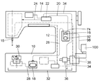
図1は、ケーシングの形状のベースプレート10、そこから垂直に突出したスタンダード12、及びベースプレート10と平行にスタンダード12の上側の端から続く水平アーム14を有するミシンの概略的な側面図である。駆動アームシャフト(図1には示さず)は従来通りにアーム14に支持されている。概略的に示した針を有する針棒15は、アームシャフトにより上下に往復して駆動可能である。
FIG. 1 is a schematic side view of a sewing machine having a
スタンダード12に、以下に明細書で詳細に言及する第1オイルタンク16が配置されている。第2オイルタンク18がケーシング10に配置されている。第1オイルタンク16は、芯管路20、ディストリビュータ22及び第2芯管路24を介して針ガイド(図示せず)の領域と繋がる。
A
別な芯管路26を介して、第1オイルタンク16が第2オイルタンク18にオイルを供給し、第2オイルタンク18は別な芯管路28を介してシャトル30に接続している。ベースプレート10の下側領域は、滴るオイルを集める役割を果たすオイルパン32を収容する。このオイルは、モーター38により駆動するポンプ36が位置するところで管路34を介してディストリビュータ22にポンプで汲み戻される。ミシン全体の別な詳細はこの文脈では重要でない。
The
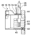
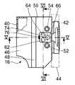
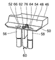
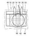
以下は、図2〜7に則したオイルタンク16の詳細な記述である。図2及び3によれば、オイルタンク16は箱枠40を有し、その形状の幾つかの細部(詳細)は図3に見られる局所的に利用可能なスペースに適合している。オイルタンク16は、ミシンのスタンダードのケーシング壁44の凹部42にフィットしている。箱枠40は、具体的には図2及び4に見られるカバー46で閉じられている。カバー46は段のついた勾配の持ち上がり領域48と実質的に板状(プレート状)の下領域50を有する。この板状領域50は、板状領域50の下面にある管56,58に通じる2つの穴52,54を有する。
The following is a detailed description of the
これらの管は図1に関連して述べた芯管路20,26を収容する。芯管路は図2及び7に示されているが、他の図にはない。
These tubes contain the
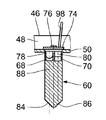
2本の管56,58の間に、浸漬体60がカバー46の板状領域50の下面に固定されており、具体的には一続きのプラスチック部品としてカバー46に一体成形されている。浸漬体60はオイルタンク16の貯蔵槽61に突出している。三角形の配置の3つの穴62,64,66が板状領域50に位置している。それらは浸漬体60に割り当てられ、浸漬体60の上側領域にある対応する凹部68,70,72に通じている。穴62,64と一直線に並んだ2つの凹部68,70は図6に示される。第3の穴66と一直線に並んだ第3の凹部72は図5に見られる。
An
これらの凹部68,70,72は別として、浸漬体60は透明材料の硬い構造、例えばアクリルガラスである。
Apart from these
ベアリングプレート74が浸漬体60の近傍のカバー46に位置している。それは具体的にはカバー46に一体成形されたデテント76によってロックされている。3つの凹部68,70,72に割り当てられた位置に、ベアリングプレート74に位置しているのは、光源としての発光ダイオード78、受光ダイオードとしてのフォトダイオード80及び別な発光ダイオード82である。フォトダイオード80及び別な発光ダイオード82は信号送信のために接続している。別な発光ダイオード82は、フォトダイオード80によりスイッチオン及びオフされるインジケータランプとして働く。
A bearing
図5及び6は、図3のV−V線及びVI−VI線における浸漬体60の、互いに直交する2つの断面図である。図6の断面図は発光ダイオード78及びフォトダイオード80を示す。図5の断面図はインジケータランプ82を示す。
5 and 6 are two cross-sectional views of the
浸漬体60の底部は2つのスロープを有する。これらはほぼ45°互いに向かって傾いており、反射表面84,86と称する。発光ダイオード78で放出された光ビーム88が第一反射表面84に当たる。浸漬体60がオイルタンク16内のオイル浴に浸っている限り、点鎖線で略図を示すように、ビームは反射表面84を通ってオイル浴に実質的に真っ直ぐに延びる。
The bottom of the
浸漬体60の底部が露出する程オイル浴が落ちると、光ビーム88がフォトダイオード80に向かって平行に反射するように2つの反射表面84,86で偏向される。フォトダイオード80は切り替えパルスを放出し、インジケータランプ82のスイッチを入れ、それが光信号を発する。
When the oil bath falls so that the bottom of the
述べたように、箱枠40の(図2及び3の右にある)壁90が、ミシンのケーシング壁44の凹部42に埋め込まれている。その結果、窓92(図1)を通してオイルタンク16が外から見える。凹部42は、インジケータランプ82が外から直接見えるように寸法決めされていないので、インジケータランプ82の光ビームは、浸漬体60の付属部品94及び45°に配された付属部品の反射表面96に導かれる。そこ(反射表面)で、光ビームは浸漬体60から90°で反射し、窓92を通って外側に出る。これは、発光ダイオード78の信号がミシンの外側における特有の位置で遠くからでも見え、スタッフの注意をオイルの欠乏に引き付けることを意味する。
As mentioned, the wall 90 (on the right of FIGS. 2 and 3) of the
図2,4,5及び6は図1にも見られるコード98を示しており、それはダイオード78〜82と供給電子部品100の間の接続を作ることを付け加えなければならない。
2, 4, 5 and 6 show the
本発明により、例えば従来のオイルタンクに関連する代わりとして使用できるコンパクトなオイルレベル監視ユニットが作られる。カバー46及び浸漬体60は一体化ユニットとして射出成形される。浸漬体60の上面のベアリングプレート74までだけ、電気接続が設けられる必要がある。可動部品も電気コード又は電子ラインもオイル浴にはない。
The present invention creates a compact oil level monitoring unit that can be used, for example, as an alternative to conventional oil tanks. The
述べたように、空間の方向、すなわち上から、横から又は下からの浸漬体60への挿入は本質的に重要ではない。オイルタンク16が一杯のとき一時的にオイルに浸り、オイルタンク16が空のときに露出する表面を浸漬体60が有することが重要である。
As stated, the insertion into the
とにかく、オイルタンク16のカバー46又は対応するカバー部材が浸漬体60と一体化して射出成形されていることが有利である。
In any case, it is advantageous that the
浸漬体60の形状も重要ではない。光源、すなわち発光ダイオード78からそれに光ビームを放出するための反射表面だけは必要不可欠である。これは、直接に又は別な反射表面を介する偏向によって実現できる。
The shape of the
もちろん、機械のベースプレート10に配置された第二オイルタンク18には、先に述べた実施形態のオイルタンク16と同様にして、本発明に従うオイル不足インジケータ又はオイルレベル監視ユニットが設けられる。しかしながら、先に述べた実施形態のように、オイルタンク16が下側オイルタンク18に接続していれば、本発明に従う上側オイルタンク16のレベル監視は特に有利である。下側オイルタンク18は管路26を介して上側タンクと接続しており、チェック弁(標示せず)が下側オイルタンク18が溢れるのを防ぐ。これは、上側オイルタンク16に十分な量のオイルがある限り、下側オイルタンク18が常に適度に満たされていることを意味する。
Of course, the
言い換えると、本発明に従うインジケータシステムによる上側オイルタンク16の監視は、両方のオイルタンク16,18が常に適度に満たされるという事実をもたらす。
In other words, monitoring the
10 ベースプレート
12 スタンダード
14 水平アーム
15 針棒
16 第1オイルタンク
18 第2オイルタンク
20 芯管路
22 ディストリビュータ
24 芯管路
26 芯管路
28 芯管路
30 シャトル
32 オイルパン
34 管路
36 ポンプ
38 モーター
40 箱枠
42 凹部
44 筐体壁
46 カバー
48 持ち上がり領域
50 下領域
52 穴
54 穴
56 管
58 管
60 浸漬体
61 貯蔵槽
62 穴
64 穴
66 穴
68 凹部
70 凹部
72 凹部
74 ベアリングプレート
76 デテント
78 発光ダイオード
80 フォトダイオード
82 発光ダイオード、インジケータランプ
84 反射表面
86 反射表面
88 光ビーム
90 壁
92 窓
94 付属部品
96 反射表面
98 コード
100 供給電子部品
10
Claims (14)
オイルタンク(16)の貯蔵槽(61)に突出し、貯蔵槽から取り外し可能な少なくとも1つの反射表面(84,86)を有する、少なくとも部分的に透明な材料で作られた浸漬体(60);
光ビーム(88)を反射表面(84,86)に放出するための光源(78);及び
反射表面(84,86)で反射する光源(78)の光ビームのビーム経路に配置された光レシーバ(80)を有し、
光レシーバ(80)は、光ビーム(88)が光レシーバ(80)に当たると、切り替えパルスを起動させるように設計されている
ことを特徴とするミシン。 In a sewing machine having an oil tank (16) for the supply of at least one lubrication point,
An immersion body (60) made of at least partly transparent material projecting into the storage tank (61) of the oil tank (16) and having at least one reflective surface (84, 86) removable from the storage tank;
A light source (78) for emitting a light beam (88) to a reflective surface (84, 86); and an optical receiver disposed in the beam path of the light beam of the light source (78) reflected by the reflective surface (84, 86) (80)
Sewing machine characterized in that the optical receiver (80) is designed to trigger a switching pulse when the light beam (88) hits the optical receiver (80).
ベアリングプレート(74)がカバー(46)に固定され、
光源(78)、光レシーバ(80)及びインジケータランプ(82)が、カバー(46)の対応する穴(62,64,66)を介して浸漬体の凹部(68,70,72)に突出していることを特徴とする請求項1〜12のいずれか一項に記載のミシン。 The immersion body (60) is an integral component of the cover (46) of the oil tank (16),
The bearing plate (74) is fixed to the cover (46),
The light source (78), the optical receiver (80) and the indicator lamp (82) project into the recesses (68, 70, 72) of the immersion body through the corresponding holes (62, 64, 66) of the cover (46). The sewing machine according to any one of claims 1 to 12, wherein
Applications Claiming Priority (2)
| Application Number | Priority Date | Filing Date | Title |
|---|---|---|---|
| DE102004018071 | 2004-04-08 | ||
| DE102004059194A DE102004059194A1 (en) | 2004-04-08 | 2004-12-09 | Sewing machine with an oil tank and immersion body for the oil reservoir of such a sewing machine |
Publications (1)
| Publication Number | Publication Date |
|---|---|
| JP2005296659A true JP2005296659A (en) | 2005-10-27 |
Family
ID=34913367
Family Applications (1)
| Application Number | Title | Priority Date | Filing Date |
|---|---|---|---|
| JP2005112071A Pending JP2005296659A (en) | 2004-04-08 | 2005-04-08 | Sewing machine with oil tank and oil-tank immersion body for sewing machine |
Country Status (7)
| Country | Link |
|---|---|
| EP (1) | EP1584726B1 (en) |
| JP (1) | JP2005296659A (en) |
| KR (1) | KR20060046612A (en) |
| CN (1) | CN1680646A (en) |
| AT (1) | ATE433512T1 (en) |
| DE (2) | DE102004059194A1 (en) |
| TW (1) | TW200536980A (en) |
Cited By (1)
| Publication number | Priority date | Publication date | Assignee | Title |
|---|---|---|---|---|
| JP2018051109A (en) * | 2016-09-30 | 2018-04-05 | Juki株式会社 | Sewing machine oil level detector |
Families Citing this family (5)
| Publication number | Priority date | Publication date | Assignee | Title |
|---|---|---|---|---|
| DE102007022050A1 (en) | 2007-05-08 | 2008-11-13 | Pfaff Industrie Maschinen Ag | Sewing machine, has drive device with lubricant storage tank having lubricant condition detector with capacitive sensor that includes capacity that is variable within range of possible filling level of lubricant based on filling level |
| KR101140303B1 (en) * | 2009-07-30 | 2012-05-02 | (주)대흥돌핀 | Head part automatic oiling apparatus of sewing machine |
| CN102965862A (en) * | 2012-12-05 | 2013-03-13 | 上海富山精密机械科技有限公司 | Oil quantity detection and alarm mechanism of industrial sewing machine |
| CN110095166A (en) * | 2018-01-29 | 2019-08-06 | 杰克缝纫机股份有限公司 | A kind of sewing machine oil amount detecting device and monitoring system |
| CN109853165A (en) * | 2019-03-12 | 2019-06-07 | 杰克缝纫机股份有限公司 | A kind of fuel-flow control structure of sewing machine lubricating oil |
Citations (3)
| Publication number | Priority date | Publication date | Assignee | Title |
|---|---|---|---|---|
| US3834235A (en) * | 1971-12-17 | 1974-09-10 | M Bouton | Liquid and solid sensing device |
| JPS61262638A (en) * | 1985-03-13 | 1986-11-20 | ネ−デルランドセ・セントラレ・オルガニザテイエ・フ−ル・テゲパスト−ナトウ−ルベテンシヤツペリ−ク・オンデルツエク | Sensor for measuring refractive index |
| JP2001129285A (en) * | 1999-11-10 | 2001-05-15 | Juki Corp | Sewing machine oil level indicator |
Family Cites Families (6)
| Publication number | Priority date | Publication date | Assignee | Title |
|---|---|---|---|---|
| US2301460A (en) * | 1940-05-27 | 1942-11-10 | Union Special Machine Co | Liquid level gauge |
| US3362224A (en) * | 1964-12-28 | 1968-01-09 | Illinois Tool Works | Liquid level indicator |
| US3648521A (en) * | 1968-10-23 | 1972-03-14 | Pasquale J Amendolia | Light indicator |
| US4711126A (en) * | 1985-03-13 | 1987-12-08 | 501 Nederlandse Centrale Organisatie Voor Toegepast-Enschappelijk Onderzoek | Sensor for the measurement of the refractive index of a fluid and/or phase boundary between two fluids by means of visible or invisible light |
| US6173609B1 (en) * | 1997-06-20 | 2001-01-16 | Optical Sensor Consultants, Inc. | Optical level sensor |
| US6578418B2 (en) * | 1997-11-24 | 2003-06-17 | Robert J. Dillon | Sight glass |
-
2004
- 2004-12-09 DE DE102004059194A patent/DE102004059194A1/en not_active Withdrawn
-
2005
- 2005-04-02 EP EP05007235A patent/EP1584726B1/en not_active Expired - Lifetime
- 2005-04-02 DE DE502005007445T patent/DE502005007445D1/en not_active Expired - Lifetime
- 2005-04-02 AT AT05007235T patent/ATE433512T1/en not_active IP Right Cessation
- 2005-04-07 TW TW094110979A patent/TW200536980A/en unknown
- 2005-04-08 KR KR1020050029197A patent/KR20060046612A/en not_active Ceased
- 2005-04-08 CN CNA200510063502XA patent/CN1680646A/en active Pending
- 2005-04-08 JP JP2005112071A patent/JP2005296659A/en active Pending
Patent Citations (3)
| Publication number | Priority date | Publication date | Assignee | Title |
|---|---|---|---|---|
| US3834235A (en) * | 1971-12-17 | 1974-09-10 | M Bouton | Liquid and solid sensing device |
| JPS61262638A (en) * | 1985-03-13 | 1986-11-20 | ネ−デルランドセ・セントラレ・オルガニザテイエ・フ−ル・テゲパスト−ナトウ−ルベテンシヤツペリ−ク・オンデルツエク | Sensor for measuring refractive index |
| JP2001129285A (en) * | 1999-11-10 | 2001-05-15 | Juki Corp | Sewing machine oil level indicator |
Cited By (1)
| Publication number | Priority date | Publication date | Assignee | Title |
|---|---|---|---|---|
| JP2018051109A (en) * | 2016-09-30 | 2018-04-05 | Juki株式会社 | Sewing machine oil level detector |
Also Published As
| Publication number | Publication date |
|---|---|
| KR20060046612A (en) | 2006-05-17 |
| EP1584726B1 (en) | 2009-06-10 |
| DE102004059194A1 (en) | 2005-10-27 |
| EP1584726A1 (en) | 2005-10-12 |
| DE502005007445D1 (en) | 2009-07-23 |
| TW200536980A (en) | 2005-11-16 |
| CN1680646A (en) | 2005-10-12 |
| ATE433512T1 (en) | 2009-06-15 |
Similar Documents
| Publication | Publication Date | Title |
|---|---|---|
| CA2671009C (en) | Handle assembly with controlled light distribution | |
| JP5867365B2 (en) | Illuminated storage box | |
| JPWO2002042990A1 (en) | Card gate mechanism in card reader | |
| US20140116569A1 (en) | Fill system and method including visual indicator device for empty condition | |
| KR200493129Y1 (en) | Oil level check device with luminus floating body | |
| KR20060046612A (en) | Sewing machines having oil tanks and oil tank locking bodies of such sewing machines | |
| JP2013108888A (en) | Liquid volume display device, electric water heater, liquid storage container, and oil level gauge | |
| CN107884036B (en) | Sewing machine oil detection device | |
| JP5328160B2 (en) | Car compartment storage structure | |
| WO2009081308A2 (en) | Container having a space for containing a liquid, comprising means for indicating the level of the liquid | |
| TWI717393B (en) | Tank with level display and compact assembly with such a tank | |
| JP2005296656A (en) | Sewing machine with lubrication device | |
| CN113445272B (en) | Put in box and cleaning equipment | |
| EP2666903A1 (en) | Laundry dryer and condensate tank | |
| US10767914B2 (en) | Icemaker and freezer | |
| JPH09159508A (en) | Oil gauge of cartridge tank | |
| JP5914230B2 (en) | Illuminated storage box | |
| US12031690B2 (en) | Flame simulation device | |
| JP7575188B2 (en) | Toilet equipment | |
| JP2006003143A (en) | Detection device for petroleum product using optical fiber | |
| KR20050116526A (en) | Washer liquid-level gauge using position finding sensor | |
| JP2564049Y2 (en) | Kerosene pump | |
| KR100367025B1 (en) | Tip to tail meter indicator equipped multistage face of reflection for vehicle | |
| KR200227203Y1 (en) | Oxygen supplier for live fish transporting vehicle | |
| KR200484204Y1 (en) | Measuring devices for meters |
Legal Events
| Date | Code | Title | Description |
|---|---|---|---|
| A621 | Written request for application examination |
Free format text: JAPANESE INTERMEDIATE CODE: A621 Effective date: 20080304 |
|
| A131 | Notification of reasons for refusal |
Free format text: JAPANESE INTERMEDIATE CODE: A131 Effective date: 20101019 |
|
| A521 | Request for written amendment filed |
Free format text: JAPANESE INTERMEDIATE CODE: A523 Effective date: 20110118 |
|
| A02 | Decision of refusal |
Free format text: JAPANESE INTERMEDIATE CODE: A02 Effective date: 20110531 |