JP2005296624A - Corneal laser surgical beam guidance system and method - Google Patents
Corneal laser surgical beam guidance system and method Download PDFInfo
- Publication number
- JP2005296624A JP2005296624A JP2004367331A JP2004367331A JP2005296624A JP 2005296624 A JP2005296624 A JP 2005296624A JP 2004367331 A JP2004367331 A JP 2004367331A JP 2004367331 A JP2004367331 A JP 2004367331A JP 2005296624 A JP2005296624 A JP 2005296624A
- Authority
- JP
- Japan
- Prior art keywords
- laser beam
- medium
- beam path
- mirror
- laser
- Prior art date
- Legal status (The legal status is an assumption and is not a legal conclusion. Google has not performed a legal analysis and makes no representation as to the accuracy of the status listed.)
- Granted
Links
- 238000000034 method Methods 0.000 title claims abstract description 10
- 230000007246 mechanism Effects 0.000 claims description 24
- 230000003213 activating effect Effects 0.000 claims 1
- 230000003287 optical effect Effects 0.000 abstract description 19
- 238000002430 laser surgery Methods 0.000 abstract description 12
- 238000001356 surgical procedure Methods 0.000 description 6
- 210000004087 cornea Anatomy 0.000 description 5
- 230000000694 effects Effects 0.000 description 3
- 238000004891 communication Methods 0.000 description 2
- 238000006073 displacement reaction Methods 0.000 description 2
- 238000011144 upstream manufacturing Methods 0.000 description 2
- 230000002301 combined effect Effects 0.000 description 1
- 238000010276 construction Methods 0.000 description 1
- 230000001186 cumulative effect Effects 0.000 description 1
- 230000009977 dual effect Effects 0.000 description 1
- 238000004519 manufacturing process Methods 0.000 description 1
- 230000003278 mimic effect Effects 0.000 description 1
Images
Classifications
-
- G—PHYSICS
- G02—OPTICS
- G02B—OPTICAL ELEMENTS, SYSTEMS OR APPARATUS
- G02B26/00—Optical devices or arrangements for the control of light using movable or deformable optical elements
- G02B26/08—Optical devices or arrangements for the control of light using movable or deformable optical elements for controlling the direction of light
- G02B26/0816—Optical devices or arrangements for the control of light using movable or deformable optical elements for controlling the direction of light by means of one or more reflecting elements
-
- A—HUMAN NECESSITIES
- A61—MEDICAL OR VETERINARY SCIENCE; HYGIENE
- A61F—FILTERS IMPLANTABLE INTO BLOOD VESSELS; PROSTHESES; DEVICES PROVIDING PATENCY TO, OR PREVENTING COLLAPSING OF, TUBULAR STRUCTURES OF THE BODY, e.g. STENTS; ORTHOPAEDIC, NURSING OR CONTRACEPTIVE DEVICES; FOMENTATION; TREATMENT OR PROTECTION OF EYES OR EARS; BANDAGES, DRESSINGS OR ABSORBENT PADS; FIRST-AID KITS
- A61F9/00—Methods or devices for treatment of the eyes; Devices for putting in contact-lenses; Devices to correct squinting; Apparatus to guide the blind; Protective devices for the eyes, carried on the body or in the hand
- A61F9/007—Methods or devices for eye surgery
- A61F9/008—Methods or devices for eye surgery using laser
- A61F9/00825—Methods or devices for eye surgery using laser for photodisruption
- A61F9/0084—Laser features or special beam parameters therefor
-
- A—HUMAN NECESSITIES
- A61—MEDICAL OR VETERINARY SCIENCE; HYGIENE
- A61F—FILTERS IMPLANTABLE INTO BLOOD VESSELS; PROSTHESES; DEVICES PROVIDING PATENCY TO, OR PREVENTING COLLAPSING OF, TUBULAR STRUCTURES OF THE BODY, e.g. STENTS; ORTHOPAEDIC, NURSING OR CONTRACEPTIVE DEVICES; FOMENTATION; TREATMENT OR PROTECTION OF EYES OR EARS; BANDAGES, DRESSINGS OR ABSORBENT PADS; FIRST-AID KITS
- A61F9/00—Methods or devices for treatment of the eyes; Devices for putting in contact-lenses; Devices to correct squinting; Apparatus to guide the blind; Protective devices for the eyes, carried on the body or in the hand
- A61F9/007—Methods or devices for eye surgery
- A61F9/008—Methods or devices for eye surgery using laser
- A61F2009/00861—Methods or devices for eye surgery using laser adapted for treatment at a particular location
- A61F2009/00872—Cornea
Landscapes
- Health & Medical Sciences (AREA)
- Physics & Mathematics (AREA)
- Ophthalmology & Optometry (AREA)
- Optics & Photonics (AREA)
- Biomedical Technology (AREA)
- Nuclear Medicine, Radiotherapy & Molecular Imaging (AREA)
- Surgery (AREA)
- Engineering & Computer Science (AREA)
- General Physics & Mathematics (AREA)
- Heart & Thoracic Surgery (AREA)
- Vascular Medicine (AREA)
- Life Sciences & Earth Sciences (AREA)
- Animal Behavior & Ethology (AREA)
- General Health & Medical Sciences (AREA)
- Public Health (AREA)
- Veterinary Medicine (AREA)
- Laser Surgery Devices (AREA)
Abstract
【課題】角膜レーザ外科療法において、レーザ・ビームを目標組織の焦点に誘導する装置および方法を提供する。
【解決手段】レーザ・ビームを生成する際、レーザ・ビームの中心ビーム路からの発散は、光学誘導コンポーネントを順次配置構成することにより、最小になる。順番に、ビームは最初に、z走査器具の中心へと案内され、これは焦点を媒体中でz方向に移動させる。次に、ビームは第1検流計ミラーの中心へと通過し、これはx方向に焦点の移動を導入する。次に、第2検流計ミラーが、ビームを第3検流計ミラーの中心へと再案内することにより、x方向の移動を補償し、ここでy方向で焦点の移動が導入される。
【選択図】図2
An apparatus and method for directing a laser beam to a focal point of a target tissue in corneal laser surgery.
When generating a laser beam, the divergence of the laser beam from the central beam path is minimized by sequentially arranging optical guidance components. In turn, the beam is first guided to the center of the z-scanning instrument, which moves the focal point in the z direction in the medium. The beam then passes to the center of the first galvanometer mirror, which introduces focus movement in the x direction. The second galvanometer mirror then re-guides the beam to the center of the third galvanometer mirror to compensate for movement in the x direction, where focus movement is introduced in the y direction.
[Selection] Figure 2
Description
本発明は概ね角膜レーザ外科療法を実行するシステムおよび方法に関する。特に、本発明は角膜レーザ外科療法を実行するためにレーザ・ビームを光学的に誘導するシステムおよび方法に関する。本発明は特に、しかし排他的ではなく、角膜レーザ外科療法のために、ビーム路をシステムの光学コンポーネント上にほぼセンタリングしたまま、レーザ・ビームを媒体中の焦点へと光学的に誘導するシステムとして有用である。 The present invention relates generally to systems and methods for performing corneal laser surgery. In particular, the present invention relates to a system and method for optically guiding a laser beam to perform corneal laser surgery. The present invention is particularly, but not exclusively, as a system for optically directing a laser beam to a focal point in a medium while maintaining the beam path substantially centered on the optical components of the system for corneal laser surgery. Useful.
角膜レーザ外科療法は、多くの予め決定した焦点の連なりにレーザ・ビームを移動させ、集束させる(つまり誘導する)必要がある。実行すべき特定の外科措置に応じて、このような予め決定した焦点は媒体(目標組織)上にあるか、媒体内にある。いずれの場合も、所期の目的は、予め決定したパターンに従い目標組織を光変更(photoalter)することである。例えば屈折性外科療法では、目標組織は通常、人間の目の角膜の間質組織であり、レーザ・ビームの誘導は、レーザ・システムの光学コンポーネント(つまりレンズおよびミラー)の移動、傾斜または再位置合わせによって達成される。 Corneal laser surgery requires the laser beam to be moved and focused (ie, guided) in a series of predetermined focal points. Depending on the particular surgical procedure to be performed, such a predetermined focus is on or in the medium (target tissue). In either case, the intended purpose is to photoalter the target tissue according to a predetermined pattern. For example, in refractive surgery, the target tissue is usually stromal tissue of the cornea of the human eye, and laser beam guidance is the movement, tilting or repositioning of the optical components of the laser system (ie lenses and mirrors) Achieved by combining.
現在使用されているレーザ外科療法システムは通常、ビームがシステムを通過するにつれ、レーザ・ビームを移動させ、案内するよう操作される二重ミラーの組合せを含む。この組合せの中で、一方のミラーは、レーザ・ビームの焦点が目標組織のx−y面のx方向に移動するよう動作する。これで、他方のミラーは、焦点が目標組織のx−y面のy方向に移動するよう動作する。その結果、このような動作ごとに、レーザ・ビームは必然的にシステムを通る中心路から離れた方向に向けられる。さらに、この効果は累積的である。したがって、レーザ・ビームが動作して、特定のレーザ外科療法パターンに合わせて「x」および「y」の動作を実行するにつれ、ビーム路の中心が、システムの下流にある光学コンポーネントの中心から外れることになる。何らかのポイントで、これらの動作を組み合わせた効果が、レーザ・システムの光学的効率および外科的精度を大幅に低下させることがある。 Currently used laser surgical systems typically include a combination of dual mirrors that are manipulated to move and guide the laser beam as it passes through the system. Within this combination, one mirror operates to move the focus of the laser beam in the x direction of the xy plane of the target tissue. Thus, the other mirror operates so that the focal point moves in the y direction of the xy plane of the target tissue. As a result, for each such operation, the laser beam is necessarily directed away from the central path through the system. Furthermore, this effect is cumulative. Thus, as the laser beam operates to perform the “x” and “y” operations for a particular laser surgical pattern, the center of the beam path deviates from the center of the optical component downstream of the system. It will be. At some point, the combined effects of these operations can significantly reduce the optical efficiency and surgical accuracy of the laser system.
以上を鑑みて、レーザ外科療法中に媒体中の焦点へとレーザ・ビームを誘導する装置で、ビームがシステムを通過するにつれ、レーザ・ビームの動作を補償して、ビームがシステムの光学コンポーネント上にほぼセンタリングした状態を維持する装置を提供することが、本発明の目的である。本発明のさらに別の目的は、角膜レーザ外科療法中に媒体中の焦点へとレーザ・ビームを誘導する装置で、目標組織中でレーザ・ビームの焦点が「x」、「y」および「z」方向に移動する間、光学要素の中心からのレーザ・ビームの変位を最小にする装置を提供することである。本発明のさらに別の目的は、角膜レーザ外科療法中に媒体中の焦点へとレーザ・ビームを誘導するために、使用しやすく、相対的に単純に製造され、費用効果が比較的高い装置を提供することである。 In view of the foregoing, an apparatus that directs a laser beam to a focal point in a medium during laser surgery, compensates for the operation of the laser beam as it passes through the system, so that the beam is on the optical components of the system. It is an object of the present invention to provide an apparatus that maintains a substantially centered state. Yet another object of the present invention is an apparatus for directing a laser beam to a focal point in a medium during corneal laser surgery where the focal point of the laser beam is “x”, “y” and “z” in the target tissue. It is to provide an apparatus that minimizes the displacement of the laser beam from the center of the optical element while moving in the “direction”. Yet another object of the present invention is to provide a device that is easy to use, relatively simple to manufacture, and relatively cost effective to direct a laser beam to a focal point in a medium during corneal laser surgery. Is to provide.
本発明によると、ビーム路に沿って媒体中の焦点までレーザ・ビームを誘導する装置は、ビーム路に沿ってレーザ・ビームを生成するレーザ光源を含む。また、レーザ・ビームを誘導するために、ビーム路に沿って第1、第2および第3走査機構が順番に配置される。この3つの走査機構を組み合わせた効果は、媒体(目標組織)中のx−y面上で焦点の動作を生成することである。本発明の好ましい実施形態では、第1、第2および第3走査機構は検流計ミラーである。この3つの走査機構に加えて、本発明の装置は、x−y面に直角であるz方向でレーザ・ビームの焦点を動作させるz走査器具も含む。本発明の一つの実施形態では、器具は音声コイル・サブアセンブリである。代替実施形態では、器具は能動ミラーである。 According to the present invention, an apparatus for directing a laser beam along a beam path to a focal point in a medium includes a laser light source that generates the laser beam along the beam path. Also, first, second and third scanning mechanisms are arranged in order along the beam path to guide the laser beam. The effect of combining these three scanning mechanisms is to produce a focal motion on the xy plane in the medium (target tissue). In a preferred embodiment of the invention, the first, second and third scanning mechanisms are galvanometer mirrors. In addition to the three scanning mechanisms, the apparatus of the present invention also includes a z-scanning instrument that moves the focal point of the laser beam in the z-direction that is perpendicular to the xy plane. In one embodiment of the invention, the instrument is a voice coil subassembly. In an alternative embodiment, the instrument is an active mirror.
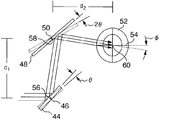
本発明で意図したように、システムの光学コンポーネントの中心からのレーザ・ビームの発散または変位は、ビーム路に沿って光学コンポーネントを適切に配置し、第3走査機構を組み込むことによって最小になる。特に、z走査器具は、最初にレーザ光源の後に整列して配置され、器具の中心でレーザ・ビームを受けるよう位置決めされる。これで、z走査器具により、レーザ・ビームは集束または発散して、ビームの焦点面のz方向動作を実行する。次に、z走査器具は、ビームを第1検流計ミラーの中心に向かって送る。光学的に、第1検流計ミラーは、ビーム路上に位置決めされて、第1検流計ミラーが「θ」の角度だけ回転するたびに、x−y面上でx方向での変化を実行する。次に、第2検流計ミラーがビーム路上で位置決めされ、第1検流計ミラーによってビーム路の発散が導入されると、それを全て補償する。特に、これは第2検流計ミラーを「2θ」の角度だけ回転し、ビーム路を第3検流計ミラーの中心に再案内することによって実行される。次に、第3ミラーを「φ」の角度だけ回転し、x−y面上でのy方向での変化を実行することができる。 As contemplated by the present invention, the divergence or displacement of the laser beam from the center of the optical components of the system is minimized by properly positioning the optical components along the beam path and incorporating a third scanning mechanism. In particular, the z-scanning instrument is initially placed in alignment after the laser source and positioned to receive the laser beam at the center of the instrument. The laser beam is now focused or diverged by the z-scan tool to perform z-direction motion of the focal plane of the beam. The z-scanning instrument then sends the beam toward the center of the first galvanometer mirror. Optically, the first galvanometer mirror is positioned on the beam path and performs a change in the x direction on the xy plane each time the first galvanometer mirror rotates by an angle of “θ”. To do. The second galvanometer mirror is then positioned on the beam path and compensates for any divergence of the beam path introduced by the first galvanometer mirror. In particular, this is done by rotating the second galvanometer mirror by an angle of “2θ” and re-guiding the beam path to the center of the third galvanometer mirror. The third mirror can then be rotated by an angle of “φ” to perform a change in the y direction on the xy plane.
構造的に、第1、第2および第3検流計ミラーの個々の回転軸線は、全てビーム路に対して直角である。さらに、第1および第2検流計ミラーの回転軸線は、相互に平行である。しかし、第3検流計ミラーの回転軸線は、第1および第2検流計ミラー双方の回転軸線に対して直角である。検流計ミラーの組合せの中で、第1ミラーと第2ミラー間の中心間距離が、第2ミラーと第3ミラー間の中心間距離と等しいことも重要である。本発明で開示するように、「中心間」距離とは、ビーム路内で光学的に位置合わせされた任意の2つのミラーの反射表面の幾何学的中心間の距離と定義される。 Structurally, the individual rotational axes of the first, second and third galvanometer mirrors are all perpendicular to the beam path. Furthermore, the rotation axes of the first and second galvanometer mirrors are parallel to each other. However, the rotation axis of the third galvanometer mirror is perpendicular to the rotation axis of both the first and second galvanometer mirrors. In the combination of galvanometer mirrors, it is also important that the center-to-center distance between the first mirror and the second mirror is equal to the center-to-center distance between the second mirror and the third mirror. As disclosed herein, “center-to-center” distance is defined as the distance between the geometric centers of the reflective surfaces of any two mirrors optically aligned in the beam path.
装置は、電子的通信でz走査器具および3つの検流計ミラーのそれぞれと接続されたコンピュータ制御装置も含むことが好ましい。これを接続した状態で、コンピュータ制御装置は、z走査器具の作用およびミラーの回転を一斉に制御する。したがって、コンピュータ制御装置は、レーザ外科療法中に媒体中の目標組織のx−y−zボリュームにおいてレーザ・ビームの焦点の動作を制御することができる。さらに、コンピュータ制御装置は、光学コンポーネントの光学特性(例えばレンズの像面湾曲)、さらに走査された媒体の光学特性(例えば屈折率)を考慮に入れるようプログラムすることができる。 The apparatus preferably also includes a computer controller connected in electronic communication with each of the z-scanning instrument and each of the three galvanometer mirrors. With this connected, the computer control device controls the action of the z-scanning instrument and the rotation of the mirror all at once. Thus, the computer controller can control the operation of the focus of the laser beam in the xyz volume of the target tissue in the medium during laser surgery. In addition, the computer controller can be programmed to take into account the optical properties of the optical component (eg, field curvature of the lens), as well as the optical properties (eg, refractive index) of the scanned media.
レーザ・ビームが上記で開示した光学コンポーネントを通過した後、ビームが媒体に入る前に、レーザ・ビームが集束レンズのほぼ中心付近に入射することが重要である。その達成を補助するため、装置は、ビーム路上で誘導用光学部品より下流に位置決めされたリレー光学部品を含む。また、本発明の好ましい実施形態では、レーザ・ビームを集束レンズへと案内するために、リレーと集束レンズとの間に2色性回転ミラーを配置することができる。また、顕微鏡を2色性回転ミラーを通して導入し、レーザ外科療法の措置中に患者の目を見るため、レーザ・ビームと位置合わせすることができる。 It is important that the laser beam be incident approximately near the center of the focusing lens after it has passed through the optical components disclosed above and before it enters the medium. To help achieve this, the apparatus includes relay optics positioned downstream from the guiding optics on the beam path. Also, in a preferred embodiment of the invention, a dichroic rotating mirror can be placed between the relay and the focusing lens to guide the laser beam to the focusing lens. A microscope can also be introduced through a dichroic rotating mirror and aligned with the laser beam for viewing the patient's eyes during a laser surgical procedure.
本発明の新規の特徴、さらに本発明自体は、その構造および動作の両方について、添付図面を添付説明と組み合わせて考慮することにより、最もよく理解され、ここで同様の参照文字は同様の部品を指す。 The novel features of the present invention, as well as the invention itself, are best understood by considering the structure and operation of the invention in combination with the accompanying drawings, wherein like reference characters refer to like parts. Point to.
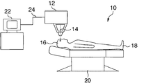
角膜レーザ外科療法を実行するシステムを図1に示し、概ね10とする。図示のように、システム10は、患者18の目16に向かってビーム路に沿ってレーザ・ビーム14を案内する外科用レーザ・ユニット12を含む。また、システム10は、患者18の目16を外科用レーザ・ユニット12と位置合わせする台20を含む。さらに、コンピュータ制御装置22は、レーザ外科療法の措置を監視し、制御するために、電気ケーブル24を介して外科用レーザ・ユニット12と電子的に連絡する。
A system for performing corneal laser surgery is shown in FIG. As shown, the
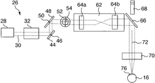
次に図2を参照すると、本発明により媒体中の焦点へとレーザ・ビーム14を誘導する光学装置が図示され、概ね26とされる。一般に、装置26は外科用レーザ・ユニット12の一体部品である。いかなる場合も、図示のように装置26は、レーザ・ビーム14を生成し、ビーム路30に沿って目16に向かってこれを案内するレーザ光源28を含む。レーザ光源28は、フェムト秒レーザ光源28、つまり約1ミクロンの波長、約100〜1000フェムト秒の範囲のパルス継続時間、および0.1から100mJの範囲のパルス・エネルギを有するレーザ・ビーム14を生成するレーザ光源であることが好ましい。
Referring now to FIG. 2, an optical device for directing the laser beam 14 to a focal point in the medium according to the present invention is illustrated and generally designated 26. In general, the
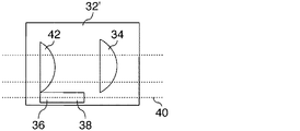
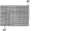
図2で示すように、本発明の装置26は、z方向に焦点を移動するためにビーム路30上で位置決めされたz走査器具32を含む。しばらく図3Aおよび図3Bを参照すると、z走査器具32の2つの代替実施形態が図示されている。図3Aでは、音声コイル・サブアセンブリ32’が、ビーム路30に固定状態で位置決めされたレンズ34を含む。レンズ34は平凸レンズであることが好ましい。また、サブアセンブリ32’は、長手方向軸線40を画定する動作可能な直線スライド38を有する音声コイル36を含む。図示のように、長手方向軸線40はビーム路30に平行である。さらに、好ましくは平凹レンズであるレンズ42は、ビーム路30に沿って直線スライド38とともに前後に動作するよう、これに装着する。図3Bで示すように、z走査器具32の代替実施形態は能動ミラー32”である。特に、ミラー32”は、「Method for Programming an Active Mirror to Mimic a Wavefront」と題されJ. Billeに対して発行された米国特許第6,220,707号で開示されたタイプでよい。図3Bを参照して認識されるように、ミラー32”は複数の個々の切子面を有し、そのうち切子面43が例示されている。切子面43は、能動ミラー32”の表面の形状を変化させて、光の入射ビーム14を変更するよう別個に動作できることが重要である。ビーム路30上のz走査器具32の位置、つまりレーザ光源28の後で装置26の残りの光学素子より上流の位置により、ビーム14は装置32の中心を通過することができ、これはビーム14を目16の焦点に集束する場合に望ましい。
As shown in FIG. 2, the
z走査器具32に加えて、装置26は走査機構44を含み、これは検流計ミラーであることが好ましく、ミラー44を「θ」の角度だけ回転するようビーム路30上で位置決めされる。ミラー44は、ビーム路30に対して直角である回転軸線46を有する。ビーム路30上では走査機構48も位置決めされ、これも検流計ミラーであることが好ましい。本発明によって予想されるように、ミラー48は、ビーム路30に対して直角であり、ミラー44の回転軸線46に平行である回転軸線50を有する。図4で示すように、ミラー48は、「2θ」の角度だけ回転するよう位置決めされる。さらに、走査機構52はミラー48と光学的に整列するよう、ビーム路30上で位置決めされる。本発明の好ましい実施形態では、走査機構52は検流計ミラーであり、角度「φ」だけ回転するようビーム路30上で位置決めされる。図2および図4で、ミラー52が、回転軸線46および50の両方に対して直角であり、ビーム路30に対して直角である回転軸線54を有することが分かる。構造的に、ミラー44の中心56とミラー48の中心58との間の距離「d1」(図4)は、中心58とミラー52の中心60との間の距離「d2」と等しい。
In addition to the z-scanning
ビーム路30に沿って続けると、図2から装置26がz走査器具32とミラー44、48および52との両方の下流に位置決めされたリレー62を含むことが分かる。図示のように、リレー62は複数のレンズを有し、そのうちレンズ64aおよび64bが例示されている。リレー62に加えて、ビーム14がリレー62を出る時、レーザ・ビーム14を目16に向かって案内するため、2色性回転ミラー66が位置決めされている。特に、回転ミラー66は、リレー62の後でビーム路30上に連続して位置決めされ、ミラー66は、ビーム路30に対してほぼ45°の角度で配向される。2色性ミラー66に加えて、本発明の装置26は、レーザ外科療法措置中に患者18の目16を見るため、2色性回転ミラー66およびビーム路30と光学的に整列する顕微鏡68を含む。
Continuing along the
さらに図2を参照すると、装置26は、レーザ・ビーム14を目16の焦点に集束するために位置決めされた集束レンズ70も含む。特に、集束レンズ70は、回転ミラー66の下流で位置決めされる。図2で示すように、集束レンズ70はレンズ多重線(multiplet)である。さらに、本発明で想定されるように、集束レンズ70は中心軸線72を画定する。リレー62は、検流計ミラー52を集束レンズ70の表面上に光学的に描像するため、集束レンズ70の上流に位置することが分かる。言い換えると、集束レンズ70を通過する前にリレー62を通るビーム14の正味効果は、検流計ミラー62および集束レンズ70が光学的に結合することである。
Still referring to FIG. 2, the
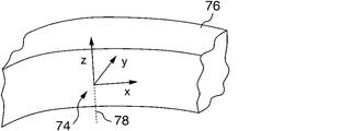
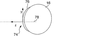
本発明の動作時には、レーザ光源28が、目16に向かって案内されるレーザ・ビーム14を生成する。特に、レーザ・ビーム14を目16の特定の層、つまり媒体内の焦点へと誘導する。本発明から予想されるように、媒体は直交x−y−z座標系を画定し、そのうち図5および図6の座標系74が例示されている。図5および図6を交互参照して分かるように、媒体16は目16の角膜76であり、座標系74のx−y面は、目16の光学軸線78に対して垂直である。図5および図6でさらに示すように、座標系74のz軸線は、光学軸線78とほぼ一致する。
In operation of the present invention, a
さらに本発明の動作を考察すると、レーザ・ビーム14はレーザ光源28を出て、ビーム路30に沿ってz走査器具32に向かって進む。本発明の一つの実施形態(図3A)では、コンピュータ制御装置22が、音声コイル・サブアセンブリ32’の直線スライド38を案内して、長手方向軸線40に沿って軸方向に規定の距離だけ移動させる。その結果、直線スライド38に装着したレンズ42も軸方向に移動する。機能的に、静止レンズ34に対して集束レンズ42が移動するので、ビーム14がレンズ42の移動方向に応じて発散または収束する。ビーム14の発散または収束の結果、座標系のx−y面は、z軸線に沿って効果的に移動し、面の焦点に集束する。ビームの発散および収束は、能動ミラー32”の使用など、当技術分野で知られている他の手段で達成してもよい。特に、レーザ・ビーム14が能動ミラー32”に到達する前に、コンピュータ制御装置22は、ミラー32”の個々の切子面、例えば43の動作を指示し、z軸線に沿った焦点に集束させる。
Considering further the operation of the present invention, the laser beam 14 exits the
レーザ・ビーム14は、z走査器具32を出た後、続いてビーム路30に沿って第1検流計ミラー44に向かう。図2および図4の相互参照から分かるように、レーザ・ビーム14はミラー44の中心に向かって案内される。図4で示したように、ミラー44は、コンピュータ制御装置22によって指示されたように、回転軸線46の周囲で「θ」の角度だけ回転する。レーザ・ビーム14がミラー44から反射すると、ビーム14の入射角度に対するミラー44の配向により、角膜76の焦点がこれに対応してx方向に移動する。特に、焦点は、座標系74のx−y面のx軸に沿って、回転角度「θ」と比例する距離「Δx」だけ移動する。
The laser beam 14 exits the z-scanning
ミラー44の回転と共同して、ミラー48は「2θ」の角度だけ回転軸線50の周囲で回転する。レーザ・ビーム14がミラー48から反射すると、レーザ・ビーム14は、ミラー44の回転によって導入された「Δx」の動作を維持しながら、ビーム路30をミラー52の中心と整列させるよう補償される。この方法で、レーザ・ビーム14はミラー52の中心から反射し、ビーム14はy方向に移動する。特に、ミラー52は、コンピュータ制御装置22に指示されて、回転軸線54の周囲で角度「φ」だけ回転する。その結果、ミラー52が角度「φ」だけ回転すると、ビーム14の焦点がx−y面のy軸線に沿って直線距離「Δy」だけ移動する。
In cooperation with the rotation of the
再び図2を参照すると、レーザ・ビーム14は第3ミラー52で反射し、リレー62に入る。リレー62内で、レーザ・ビーム14はレンズ64aおよび64bを通過し、その間ビーム路30は、レーザ・ビーム14が集束レンズ70に入射した場合に集束レンズ70の中心軸線72上にセンタリングするよう位置決めされる。特に、レーザ・ビーム14は、レンズ64aおよび64bによって集束し、y方向ミラー52を集束レンズ70と一致するよう光学的に位置決めする。したがって、ミラー52は、ビーム14が集束レンズ70に当たる前に、ビーム14の入射角度を変化させる。しかし、ビーム14がミラー52から反射し、リレー62を通過する時、ビーム14が集束レンズ70の中心から離れる横方向の移動はない。レーザ・ビーム14がリレー62を出て、回転ミラー66から反射する時、回転ミラー66は、ビーム14を集束レンズ70に向かって案内する。集束レンズ70において、レーザ・ビーム14はレンズ70の中心区間に当たる。レーザ・ビーム14が集束レンズ70を通過する時、レーザ・ビーム14は、目16の角膜76の望ましい焦点に集束する。レーザ外科療法措置の過程を通して、システムのオペレータ(図示せず)は、2色性回転ミラー66と整列した顕微鏡68を通して、患者18の目16を見ることができる。
Referring again to FIG. 2, the laser beam 14 is reflected by the
本明細書で図示し、詳細に開示した角膜レーザ外科療法の特定のビーム誘導システムは、目的を達成し、前述したような利点を提供することが十分にできるが、これは本発明の現在好ましい実施形態の例示にすぎず、請求の範囲に記載されたものを除き、本明細書で示した構造または設計の詳細に制限がないことを理解されたい。 While the particular beam guidance system of corneal laser surgery shown and disclosed in detail herein is sufficient to achieve the objective and provide the advantages as described above, this is presently preferred of the present invention. It should be understood that the embodiments are merely illustrative and that the details of construction or design shown herein are not limiting, except as described in the claims.
10 システム
12 外科用レーザ・ユニット
14 レーザ・ビーム
16 目
18 患者
20 台
22 コンピュータ制御装置
24 電気ケーブル
26 装置
28 レーザ光源
30 ビーム路
32 z走査器具
32’ 音声コイル・サブアセンブリ
32” 能動ミラー
34 レンズ
38 直線スライド
43 切子面
44 ミラー
46 回転軸線
48 走査機構
50 回転軸線
52 走査機構
54 回転軸線
56 中心
58 中心
60 中心
62 リレー
64 レンズ
66 回転ミラー
68 顕微鏡
70 集束レンズ
72 中心軸線
74 座標系
76 角膜
78 光学軸線
10
Claims (5)
レーザ・ビームをビーム路に沿って媒体へと案内するレーザ光源と、
レーザ・ビームを媒体のx方向に移動させるため、ビーム路上で位置決めされた第1走査機構と、
レーザ・ビームの動作をx方向で補償するために、ビーム路上で位置決めされた第2走査機構と、
レーザ・ビームを媒体のy方向に移動させるため、ビーム路上で位置決めされた第3走査機構と、
焦点をz方向に移動させるz走査器具と、
レーザ・ビームを媒体のx−y面の焦点に向かって誘導するために、前記第1、前記第2および前記第3走査機構、および前記z走査器具の動作を一斉に制御する手段とを備える装置。 An apparatus for directing a laser beam to the focal point of a medium, wherein the medium defines an orthogonal xyz coordinate system;
A laser light source that guides the laser beam along the beam path to the medium;
A first scanning mechanism positioned on the beam path for moving the laser beam in the x-direction of the medium;
A second scanning mechanism positioned on the beam path to compensate for laser beam motion in the x direction;
A third scanning mechanism positioned on the beam path to move the laser beam in the y direction of the medium;
A z-scanning instrument that moves the focal point in the z-direction;
Means for simultaneously controlling the operation of the first, second and third scanning mechanisms and the z-scanning instrument to direct the laser beam toward the focal point of the xy plane of the medium. apparatus.
レーザ・ビームをビーム路に沿ってz走査器具の中心に案内するステップを含み、z走査器具が、焦点の位置を目標組織内でz方向で変化させるために動作可能であり、さらに、
レーザ・ビームをz走査器具の中心から第1走査機構の中心へと通過させるステップを含み、第1走査機構が、ビーム路を変更し、目標組織の焦点の位置にx方向の変化を導入するよう回転可能であり、さらに、
レーザ・ビームを第3走査機構の中心に再案内することにより、変更したビーム路を補償させるために第2走査機構を回転するステップを含み、第3走査機構が、ビーム路を変更し、目標組織の焦点の位置にy方向の変化を導入するよう回転可能である方法。 By moving the focus of the laser beam through the target tissue,
Guiding the laser beam along the beam path to the center of the z-scanning instrument, wherein the z-scanning instrument is operable to change the position of the focal point in the target tissue in the z-direction;
Passing the laser beam from the center of the z-scanning instrument to the center of the first scanning mechanism, wherein the first scanning mechanism changes the beam path and introduces a change in the x-direction at the focal position of the target tissue. Is rotatable, and
Rotating the second scanning mechanism to compensate for the changed beam path by re-guiding the laser beam to the center of the third scanning mechanism, the third scanning mechanism changing the beam path, A method that is rotatable to introduce a change in the y-direction at the focal position of the tissue.
レーザ・ビームをビーム路に沿って媒体へと案内するよう、レーザ光源を起動するステップと、
焦点をz方向に移動させるため、レーザ・ビームをz走査器具へと案内するステップと、
第1検流計ミラーを第1回転軸線の周囲で角度「θ」だけ回転させるステップと、
第2検流計ミラーを第2回転軸線の周囲で角度「2θ」だけ回転させるステップと、
第3検流計ミラーを第3回転軸線の周囲で角度「φ」だけ回転させるステップと、
レーザ・ビームを焦点に向かって媒体のx−y面で誘導するために、前記z走査器具、および前記第1、前記第2および前記第3検流計ミラーの回転を一斉に制御するステップとを含む方法。
A method of directing a laser beam to the focal point of the medium, the medium defining an orthogonal xyz coordinate system;
Activating a laser light source to guide the laser beam along the beam path to the medium;
Directing the laser beam to a z-scanning instrument to move the focal point in the z-direction;
Rotating the first galvanometer mirror about the first axis of rotation by an angle “θ”;
Rotating the second galvanometer mirror about the second axis of rotation by an angle “2θ”;
Rotating the third galvanometer mirror about the third axis of rotation by an angle “φ”;
Simultaneously controlling the rotation of the z-scanning instrument and the first, second and third galvanometer mirrors to direct a laser beam toward the focal point in the xy plane of the medium; Including methods.
Applications Claiming Priority (2)
| Application Number | Priority Date | Filing Date | Title |
|---|---|---|---|
| US10/821,402 US7618415B2 (en) | 2004-04-09 | 2004-04-09 | Beam steering system for corneal laser surgery |
| US821402 | 2004-04-09 |
Publications (2)
| Publication Number | Publication Date |
|---|---|
| JP2005296624A true JP2005296624A (en) | 2005-10-27 |
| JP4837910B2 JP4837910B2 (en) | 2011-12-14 |
Family
ID=34912732
Family Applications (1)
| Application Number | Title | Priority Date | Filing Date |
|---|---|---|---|
| JP2004367331A Expired - Lifetime JP4837910B2 (en) | 2004-04-09 | 2004-12-20 | Corneal laser surgical beam guidance system and method |
Country Status (3)
| Country | Link |
|---|---|
| US (2) | US7618415B2 (en) |
| EP (1) | EP1584310A1 (en) |
| JP (1) | JP4837910B2 (en) |
Cited By (9)
| Publication number | Priority date | Publication date | Assignee | Title |
|---|---|---|---|---|
| JP2009172374A (en) * | 2008-01-21 | 2009-08-06 | Ziemer Holding Ag | Device for treating eye tissue |
| JP2010072645A (en) * | 2008-09-16 | 2010-04-02 | Sie Ag Surgical Instrument Engineering | Device and method for deflecting laser beam |
| JP2013500130A (en) * | 2009-07-29 | 2013-01-07 | アルコン レンゼックス, インコーポレーテッド | Optical system for laser for ophthalmic surgery |
| JP2013500132A (en) * | 2009-07-29 | 2013-01-07 | アルコン レンゼックス, インコーポレーテッド | Optical system with multiple scanners for ophthalmic surgical lasers |
| JP2013500133A (en) * | 2009-07-29 | 2013-01-07 | アルコン レンゼックス, インコーポレーテッド | Optical system with movable lens for ophthalmic surgical lasers |
| JP2013500131A (en) * | 2009-07-29 | 2013-01-07 | アルコン レンゼックス, インコーポレーテッド | Optical system for laser for ophthalmic surgery |
| KR101243998B1 (en) | 2008-04-22 | 2013-03-18 | 웨이브라이트 게엠베하 | Device for laser-optical eye surgery |
| US8979264B2 (en) | 2008-09-16 | 2015-03-17 | Sie Ag, Surgical Instrument Engineering | Device and method for deflecting a laser beam |
| JP2015109988A (en) * | 2009-07-29 | 2015-06-18 | アルコン レンゼックス, インコーポレーテッド | Optical system for laser for ophthalmic operation |
Families Citing this family (40)
| Publication number | Priority date | Publication date | Assignee | Title |
|---|---|---|---|---|
| US7238176B2 (en) * | 2004-04-29 | 2007-07-03 | 20/10 Perfect Vision Optische Geraete Gmbh | Method for intrastromal photodisruption of dome-shaped surfaces |
| US20070106285A1 (en) * | 2005-11-09 | 2007-05-10 | Ferenc Raksi | Laser scanner |
| US20070219541A1 (en) * | 2006-03-14 | 2007-09-20 | Intralase Corp. | System and method for ophthalmic laser surgery on a cornea |
| US9028069B2 (en) * | 2006-07-21 | 2015-05-12 | Ziemer Holding Ag | Ophthalmological device |
| DE102006046370B4 (en) * | 2006-09-29 | 2025-07-17 | Carl Zeiss Meditec Ag | Device and method for material processing using a transparent contact element |
| WO2009033111A2 (en) | 2007-09-06 | 2009-03-12 | Lensx Lasers, Inc. | Precise targeting of surgical photodisruption |
| US20090118716A1 (en) * | 2007-11-07 | 2009-05-07 | Intralase, Inc. | System and method for scanning a pulsed laser beam |
| US8409179B2 (en) * | 2007-12-17 | 2013-04-02 | Technolas Perfect Vision Gmbh | System for performing intrastromal refractive surgery |
| US9108270B2 (en) | 2008-01-02 | 2015-08-18 | Amo Development, Llc | System and method for scanning a pulsed laser beam |
| US9101446B2 (en) | 2008-01-02 | 2015-08-11 | Intralase Corp. | System and method for scanning a pulsed laser beam |
| WO2010069987A1 (en) * | 2008-12-19 | 2010-06-24 | Deutsches Krebsforschungszentrum | Method and device for dynamically shifting a light beam relative to an optic which focuses the light beam |
| US20110028949A1 (en) * | 2009-07-29 | 2011-02-03 | Lensx Lasers, Inc. | Optical System for Ophthalmic Surgical Laser |
| US8267925B2 (en) * | 2009-07-29 | 2012-09-18 | Alcon Lensx, Inc. | Optical system for ophthalmic surgical laser |
| WO2011032165A2 (en) * | 2009-09-14 | 2011-03-17 | Memorial Sloan-Kettering Cancer Center | Apparatus, system and method for providing laser steering and focusing for incision, excision and ablation of tissue in minimally-invasive surgery |
| US8506559B2 (en) * | 2009-11-16 | 2013-08-13 | Alcon Lensx, Inc. | Variable stage optical system for ophthalmic surgical laser |
| KR101315736B1 (en) | 2011-05-30 | 2013-10-14 | 주식회사 한빛나노바이오테크 | Device for treating eyeball using femto laser |
| US9259354B2 (en) * | 2011-06-09 | 2016-02-16 | KeLoTec, Inc. | Laser delivery system for eye surgery |
| US9931712B2 (en) * | 2012-01-11 | 2018-04-03 | Pim Snow Leopard Inc. | Laser drilling and trepanning device |
| US10182943B2 (en) | 2012-03-09 | 2019-01-22 | Alcon Lensx, Inc. | Adjustable pupil system for surgical laser systems |
| US8852177B2 (en) | 2012-03-09 | 2014-10-07 | Alcon Lensx, Inc. | Spatio-temporal beam modulator for surgical laser systems |
| US9629750B2 (en) | 2012-04-18 | 2017-04-25 | Technolas Perfect Vision Gmbh | Surgical laser unit with variable modes of operation |
| US9587804B2 (en) | 2012-05-07 | 2017-03-07 | Chia Ming Chen | Light control systems and methods |
| KR101542680B1 (en) * | 2013-01-03 | 2015-08-06 | 주식회사 나노포토닉스 | Three-dimensional optical scanner, an objective lens having a finite-sized object plane and a Z scanner capable of simultaneously controlling the diverging angle and the beam diameter of a diverging beam exiting from it |
| US10245180B2 (en) | 2013-01-16 | 2019-04-02 | Ziemer Ophthalmic Systems Ag | Ophthalmological device for treating eye tissue |
| EP2756828B1 (en) * | 2013-01-16 | 2019-02-27 | Ziemer Ophthalmic Systems AG | Ophthalmologic apparatus for the treatment of eye tissue |
| US11653874B2 (en) | 2013-02-01 | 2023-05-23 | Acceleritas Corporation | Method and system for characterizing tissue in three dimensions using multimode optical measurements |
| WO2014158615A1 (en) | 2013-03-13 | 2014-10-02 | Optimedica Corporation | Laser eye surgery system |
| US10751217B2 (en) | 2013-03-13 | 2020-08-25 | Amo Development, Llc | Free floating patient interface for laser surgery system |
| US9423879B2 (en) | 2013-06-28 | 2016-08-23 | Chia Ming Chen | Systems and methods for controlling device operation according to hand gestures |
| US9717118B2 (en) | 2013-07-16 | 2017-07-25 | Chia Ming Chen | Light control systems and methods |
| EP2837368A3 (en) * | 2013-08-17 | 2015-07-22 | Nidek Co., Ltd. | Ophthalmic laser surgical apparatus |
| WO2015057306A1 (en) * | 2013-08-30 | 2015-04-23 | Nowatzyk Andreas G | Optical beam scanning system having a synthetic center of beam rotation |
| CN106796020A (en) | 2014-04-29 | 2017-05-31 | 陈家铭 | Lighting control system and method |
| RU2563448C1 (en) * | 2014-05-22 | 2015-09-20 | Общество С Ограниченной Ответственностью "Оптосистемы" | Ophthalmosurgical laser system |
| US9995627B2 (en) | 2014-07-31 | 2018-06-12 | Smiths Detection Inc. | Raster optic device for optical hyper spectral scanning |
| WO2016209312A1 (en) * | 2015-06-23 | 2016-12-29 | Amo Development, Llc | Compact ultra-short pulsed laser eye surgery workstation |
| US12396890B2 (en) | 2017-02-09 | 2025-08-26 | Norlase Aps | Apparatus for photothermal ophthalmic treatment |
| WO2018146070A2 (en) | 2017-02-09 | 2018-08-16 | Norlase Aps | Apparatus for photothermal ophthalmic treatment |
| DE102018208752B4 (en) * | 2018-06-04 | 2024-08-22 | Fraunhofer-Gesellschaft zur Förderung der angewandten Forschung e.V. | Device and method for machining workpieces that are difficult to access and use of a device |
| DE102020113693B4 (en) * | 2020-05-20 | 2023-02-23 | Schwind Eye-Tech-Solutions Gmbh | Beam deflection device for a laser device, laser device, method for generating a laser pattern and computer program and computer-readable medium |
Citations (6)
| Publication number | Priority date | Publication date | Assignee | Title |
|---|---|---|---|---|
| JPH01262836A (en) * | 1988-02-02 | 1989-10-19 | Intelligent Surgical Lasers Inc | Three-dimensional laser beam guide apparatus |
| DE4026130A1 (en) * | 1990-08-17 | 1992-02-20 | Siemens Ag | DEVICE FOR DEFLECTING A LIGHT BEAM |
| JPH05228673A (en) * | 1992-02-18 | 1993-09-07 | Toshiba Corp | Laser processing equipment |
| JPH06246470A (en) * | 1993-03-02 | 1994-09-06 | Hitachi Constr Mach Co Ltd | High-speed laser processing device |
| JP2001272618A (en) * | 2000-03-24 | 2001-10-05 | Shibaura Mechatronics Corp | Scanning optical unit |
| JP2002178182A (en) * | 2000-12-14 | 2002-06-25 | Hitachi Via Mechanics Ltd | Laser beam machine |
Family Cites Families (38)
| Publication number | Priority date | Publication date | Assignee | Title |
|---|---|---|---|---|
| US3973825A (en) * | 1974-12-30 | 1976-08-10 | Xerox Corporation | Flat field scanning system |
| FR2341128A1 (en) * | 1976-02-16 | 1977-09-09 | Essilor Int | MIRROR ORIENTATION DEVICE FOR LASER LEVELING INSTRUMENT |
| JPS6025133B2 (en) * | 1976-04-28 | 1985-06-17 | 旭光学工業株式会社 | manipulator |
| US4099880A (en) * | 1976-08-11 | 1978-07-11 | Tsutomu Kano | Method and an apparatus for stereoscopic measurement utilizing a three-dimensional image |
| US4091274A (en) | 1976-12-22 | 1978-05-23 | United Technologies Corporation | Active laser mirror system |
| US4277381A (en) * | 1977-11-29 | 1981-07-07 | Exxon Research & Engineering Co. | Process for the formation of elastomeric blends of a sulfonated elastomeric polymer |
| DE3001244A1 (en) | 1979-01-16 | 1980-07-24 | Canon Kk | FOCUSING SYSTEM FOR A BASIC EYE CAMERA |
| DE3422143A1 (en) | 1984-06-14 | 1985-12-19 | Josef Prof. Dr. Bille | WAFER INSPECTION DEVICE |
| DE3427611A1 (en) | 1984-07-26 | 1988-06-09 | Bille Josef | LASER BEAM LITHOGRAPH |
| US4725709A (en) * | 1984-09-25 | 1988-02-16 | Siemens Aktiengesellschaft | Apparatus having a sweep arrangement for non-contacting modification of an article |
| GB2179176A (en) | 1985-08-14 | 1987-02-25 | Philip Howard Butler | Apparatus for moving a plane mirror |
| EP0236377B1 (en) | 1985-09-11 | 1992-06-03 | G. Rodenstock Instrumente Gmbh | Device for generating a laser spot of controllable size |
| SE462257B (en) * | 1986-04-22 | 1990-05-28 | Morita Mfg | LASER TYPE PIECE |
| DE3620744A1 (en) | 1986-06-20 | 1987-12-23 | Rodenstock Instr | DEVICE FOR TREATING THE EYE WITH A LASER |
| US5206763A (en) * | 1989-05-09 | 1993-04-27 | Macken John A | Corrective optics for rectangular laser beams |
| US5152759A (en) | 1989-06-07 | 1992-10-06 | University Of Miami, School Of Medicine, Dept. Of Ophthalmology | Noncontact laser microsurgical apparatus |
| JPH04356038A (en) * | 1991-01-17 | 1992-12-09 | Pioneer Electron Corp | Color decomposition and composition optical system |
| US5168491A (en) * | 1991-02-25 | 1992-12-01 | Olympus Optical Co., Ltd. | Method for controlling radiation power of a laser beam irradiated onto a recording medium |
| JPH07503382A (en) * | 1991-11-06 | 1995-04-13 | ライ,シュイ,ティー. | Corneal surgery device and method |
| IL100664A0 (en) * | 1992-01-15 | 1992-09-06 | Laser Ind Ltd | Method and apparatus for controlling a laser beam |
| US20020002369A1 (en) * | 1993-08-23 | 2002-01-03 | Hood Larry L. | Method and apparatus for modifying visual acuity by moving a focal point of energy within a cornea |
| US5480396A (en) | 1994-12-09 | 1996-01-02 | Simon; Gabriel | Laser beam ophthalmological surgery method and apparatus |
| US6074382A (en) * | 1997-08-29 | 2000-06-13 | Asah Medico A/S | Apparatus for tissue treatment |
| US6165170A (en) * | 1998-01-29 | 2000-12-26 | International Business Machines Corporation | Laser dermablator and dermablation |
| JP3848492B2 (en) * | 1998-09-04 | 2006-11-22 | 株式会社ニデック | Cornea surgery device |
| US6547397B1 (en) * | 2000-04-19 | 2003-04-15 | Laser Projection Technologies, Inc. | Apparatus and method for projecting a 3D image |
| JP4459530B2 (en) * | 2000-08-29 | 2010-04-28 | 三菱電機株式会社 | Laser processing equipment |
| US20040102765A1 (en) * | 2001-03-27 | 2004-05-27 | Karsten Koenig | Method for the minimal-to non-invase optical treatment of tissues of the eye and for diagnosis thereof and device for carrying out said method |
| US6770546B2 (en) * | 2001-07-30 | 2004-08-03 | Semiconductor Energy Laboratory Co., Ltd. | Method of manufacturing semiconductor device |
| US6610051B2 (en) | 2001-10-12 | 2003-08-26 | 20/10 Perfect Vision Optische Geraete Gmbh | Device and method for performing refractive surgery |
| US6751033B2 (en) * | 2001-10-12 | 2004-06-15 | Intralase Corp. | Closed-loop focal positioning system and method |
| US6984802B2 (en) * | 2001-11-15 | 2006-01-10 | Mitsubishi Denki Kabushiki Kaisha | Laser beam machining device |
| US6666857B2 (en) * | 2002-01-29 | 2003-12-23 | Robert F. Smith | Integrated wavefront-directed topography-controlled photoablation |
| JP3822188B2 (en) * | 2002-12-26 | 2006-09-13 | 日立ビアメカニクス株式会社 | Multi-beam laser drilling machine |
| TWI275439B (en) * | 2003-05-19 | 2007-03-11 | Mitsubishi Electric Corp | Laser processing apparatus |
| US7796243B2 (en) * | 2004-06-09 | 2010-09-14 | National Research Council Of Canada | Detection and monitoring of changes in mineralized tissues or calcified deposits by optical coherence tomography and Raman spectroscopy |
| US7923306B2 (en) * | 2004-06-18 | 2011-04-12 | Electro Scientific Industries, Inc. | Semiconductor structure processing using multiple laser beam spots |
| US8049135B2 (en) * | 2004-06-18 | 2011-11-01 | Electro Scientific Industries, Inc. | Systems and methods for alignment of laser beam(s) for semiconductor link processing |
-
2004
- 2004-04-09 US US10/821,402 patent/US7618415B2/en active Active
- 2004-12-20 JP JP2004367331A patent/JP4837910B2/en not_active Expired - Lifetime
-
2005
- 2005-01-17 EP EP05075117A patent/EP1584310A1/en not_active Withdrawn
-
2008
- 2008-02-08 US US12/028,687 patent/US7662147B2/en not_active Expired - Lifetime
Patent Citations (6)
| Publication number | Priority date | Publication date | Assignee | Title |
|---|---|---|---|---|
| JPH01262836A (en) * | 1988-02-02 | 1989-10-19 | Intelligent Surgical Lasers Inc | Three-dimensional laser beam guide apparatus |
| DE4026130A1 (en) * | 1990-08-17 | 1992-02-20 | Siemens Ag | DEVICE FOR DEFLECTING A LIGHT BEAM |
| JPH05228673A (en) * | 1992-02-18 | 1993-09-07 | Toshiba Corp | Laser processing equipment |
| JPH06246470A (en) * | 1993-03-02 | 1994-09-06 | Hitachi Constr Mach Co Ltd | High-speed laser processing device |
| JP2001272618A (en) * | 2000-03-24 | 2001-10-05 | Shibaura Mechatronics Corp | Scanning optical unit |
| JP2002178182A (en) * | 2000-12-14 | 2002-06-25 | Hitachi Via Mechanics Ltd | Laser beam machine |
Cited By (9)
| Publication number | Priority date | Publication date | Assignee | Title |
|---|---|---|---|---|
| JP2009172374A (en) * | 2008-01-21 | 2009-08-06 | Ziemer Holding Ag | Device for treating eye tissue |
| KR101243998B1 (en) | 2008-04-22 | 2013-03-18 | 웨이브라이트 게엠베하 | Device for laser-optical eye surgery |
| JP2010072645A (en) * | 2008-09-16 | 2010-04-02 | Sie Ag Surgical Instrument Engineering | Device and method for deflecting laser beam |
| US8979264B2 (en) | 2008-09-16 | 2015-03-17 | Sie Ag, Surgical Instrument Engineering | Device and method for deflecting a laser beam |
| JP2013500130A (en) * | 2009-07-29 | 2013-01-07 | アルコン レンゼックス, インコーポレーテッド | Optical system for laser for ophthalmic surgery |
| JP2013500132A (en) * | 2009-07-29 | 2013-01-07 | アルコン レンゼックス, インコーポレーテッド | Optical system with multiple scanners for ophthalmic surgical lasers |
| JP2013500133A (en) * | 2009-07-29 | 2013-01-07 | アルコン レンゼックス, インコーポレーテッド | Optical system with movable lens for ophthalmic surgical lasers |
| JP2013500131A (en) * | 2009-07-29 | 2013-01-07 | アルコン レンゼックス, インコーポレーテッド | Optical system for laser for ophthalmic surgery |
| JP2015109988A (en) * | 2009-07-29 | 2015-06-18 | アルコン レンゼックス, インコーポレーテッド | Optical system for laser for ophthalmic operation |
Also Published As
| Publication number | Publication date |
|---|---|
| US20080147051A1 (en) | 2008-06-19 |
| JP4837910B2 (en) | 2011-12-14 |
| US20050228366A1 (en) | 2005-10-13 |
| US7618415B2 (en) | 2009-11-17 |
| US7662147B2 (en) | 2010-02-16 |
| EP1584310A1 (en) | 2005-10-12 |
Similar Documents
| Publication | Publication Date | Title |
|---|---|---|
| JP4837910B2 (en) | Corneal laser surgical beam guidance system and method | |
| US11020272B2 (en) | Laser scanner | |
| CN109963535B (en) | Integrated ophthalmic surgical system | |
| JP5019794B2 (en) | Ophthalmic device for destroying ocular tissue | |
| JP6127090B2 (en) | Scanning device | |
| US8088124B2 (en) | System and method for precise beam positioning in ocular surgery | |
| JPH0412976B2 (en) | ||
| RU2747034C2 (en) | Radiation-based skin treatment device and method | |
| JP2012529312A (en) | Ophthalmic laser surgery device | |
| US10092446B2 (en) | Laser scanner apparatus and method | |
| US10010451B2 (en) | Ophthalmic laser surgical apparatus | |
| CN118356297A (en) | Multi-wavelength medical laser systems | |
| WO2009101696A1 (en) | Method for operating eye ball movement tracking device with visual axis and light beam projection axis aligned | |
| JP2013078398A (en) | Laser operation apparatus for ophthalmology | |
| US20250318955A1 (en) | System and methods for treating glaucoma with laser pulses | |
| WO2014074934A2 (en) | Laser scanner apparatus and method |
Legal Events
| Date | Code | Title | Description |
|---|---|---|---|
| A621 | Written request for application examination |
Free format text: JAPANESE INTERMEDIATE CODE: A621 Effective date: 20071101 |
|
| A711 | Notification of change in applicant |
Free format text: JAPANESE INTERMEDIATE CODE: A711 Effective date: 20100202 |
|
| A521 | Request for written amendment filed |
Free format text: JAPANESE INTERMEDIATE CODE: A821 Effective date: 20100202 |
|
| A131 | Notification of reasons for refusal |
Free format text: JAPANESE INTERMEDIATE CODE: A131 Effective date: 20100702 |
|
| A977 | Report on retrieval |
Free format text: JAPANESE INTERMEDIATE CODE: A971007 Effective date: 20100701 |
|
| A601 | Written request for extension of time |
Free format text: JAPANESE INTERMEDIATE CODE: A601 Effective date: 20101004 |
|
| A602 | Written permission of extension of time |
Free format text: JAPANESE INTERMEDIATE CODE: A602 Effective date: 20101007 |
|
| A521 | Request for written amendment filed |
Free format text: JAPANESE INTERMEDIATE CODE: A523 Effective date: 20101029 |
|
| A02 | Decision of refusal |
Free format text: JAPANESE INTERMEDIATE CODE: A02 Effective date: 20110401 |
|
| A521 | Request for written amendment filed |
Free format text: JAPANESE INTERMEDIATE CODE: A523 Effective date: 20110729 |
|
| A911 | Transfer to examiner for re-examination before appeal (zenchi) |
Free format text: JAPANESE INTERMEDIATE CODE: A911 Effective date: 20110808 |
|
| TRDD | Decision of grant or rejection written | ||
| A01 | Written decision to grant a patent or to grant a registration (utility model) |
Free format text: JAPANESE INTERMEDIATE CODE: A01 Effective date: 20110916 |
|
| A01 | Written decision to grant a patent or to grant a registration (utility model) |
Free format text: JAPANESE INTERMEDIATE CODE: A01 |
|
| A61 | First payment of annual fees (during grant procedure) |
Free format text: JAPANESE INTERMEDIATE CODE: A61 Effective date: 20110929 |
|
| FPAY | Renewal fee payment (event date is renewal date of database) |
Free format text: PAYMENT UNTIL: 20141007 Year of fee payment: 3 |
|
| R150 | Certificate of patent or registration of utility model |
Ref document number: 4837910 Country of ref document: JP Free format text: JAPANESE INTERMEDIATE CODE: R150 Free format text: JAPANESE INTERMEDIATE CODE: R150 |
|
| R250 | Receipt of annual fees |
Free format text: JAPANESE INTERMEDIATE CODE: R250 |
|
| R250 | Receipt of annual fees |
Free format text: JAPANESE INTERMEDIATE CODE: R250 |
|
| R250 | Receipt of annual fees |
Free format text: JAPANESE INTERMEDIATE CODE: R250 |
|
| R250 | Receipt of annual fees |
Free format text: JAPANESE INTERMEDIATE CODE: R250 |
|
| R250 | Receipt of annual fees |
Free format text: JAPANESE INTERMEDIATE CODE: R250 |
|
| R250 | Receipt of annual fees |
Free format text: JAPANESE INTERMEDIATE CODE: R250 |
|
| R250 | Receipt of annual fees |
Free format text: JAPANESE INTERMEDIATE CODE: R250 |
|
| R250 | Receipt of annual fees |
Free format text: JAPANESE INTERMEDIATE CODE: R250 |
|
| R250 | Receipt of annual fees |
Free format text: JAPANESE INTERMEDIATE CODE: R250 |
|
| R250 | Receipt of annual fees |
Free format text: JAPANESE INTERMEDIATE CODE: R250 |
|
| R250 | Receipt of annual fees |
Free format text: JAPANESE INTERMEDIATE CODE: R250 |
|
| EXPY | Cancellation because of completion of term |