JP2005296531A - Electric vacuum cleaner - Google Patents
Electric vacuum cleaner Download PDFInfo
- Publication number
- JP2005296531A JP2005296531A JP2004120988A JP2004120988A JP2005296531A JP 2005296531 A JP2005296531 A JP 2005296531A JP 2004120988 A JP2004120988 A JP 2004120988A JP 2004120988 A JP2004120988 A JP 2004120988A JP 2005296531 A JP2005296531 A JP 2005296531A
- Authority
- JP
- Japan
- Prior art keywords
- filter
- dust collection
- vacuum cleaner
- dust
- lid
- Prior art date
- Legal status (The legal status is an assumption and is not a legal conclusion. Google has not performed a legal analysis and makes no representation as to the accuracy of the status listed.)
- Pending
Links
Images
Landscapes
- Electric Suction Cleaners (AREA)
- Filters For Electric Vacuum Cleaners (AREA)
Abstract
【課題】
従来は集塵フィルターの表面積を有効に活用して吸引力の低下を防ぐために集塵室内壁に凸状のリブを設けて、風の流れる空間を確保していたが、凸状のリブに直接、集塵フィルターが当たるため、集塵フィルターが破損して塵埃が集塵室に漏れる危険性があった。
【解決手段】
集塵室開口を覆う蓋体の集塵室側にフィルターを保持する保持部材を設け、この保持部材には、前記フィルターを収納するフィルター収納部と、該フィルター収納部の外周に形成された流路空間とを設けた。
【選択図】 図1
【Task】
Conventionally, in order to effectively utilize the surface area of the dust collection filter and prevent a reduction in suction force, a convex rib was provided on the inner wall of the dust collection chamber to secure a space for air flow. Since the dust collecting filter hits, there is a risk that the dust collecting filter is damaged and the dust leaks into the dust collecting chamber.
[Solution]
A holding member that holds the filter is provided on the dust collection chamber side of the lid that covers the dust collection chamber opening. The holding member includes a filter storage portion that stores the filter and a flow formed on the outer periphery of the filter storage portion. Road space was established.
[Selection] Figure 1
Description
本発明は、電気掃除機に関するものである。 The present invention relates to a vacuum cleaner.
状来の電気掃除機は、集塵室内に集塵フィルターを装着し、電動送風機を運転させることにより集塵フィルター内に塵埃を集塵するようにしている。集塵フィルター内に塵埃が蓄積してくると集塵フィルターは徐々に目詰まりを始めて、しだいに吸引力が低下してくる。このとき集塵フィルター内部の圧力よりも集塵室202内部の圧力の方が負圧として大きいため、集塵フィルターは集塵室の内壁にはりついてしまい、風の流れる空間が減少して吸引力が低下する原因になっていた。そこで、集塵フィルターの表面積を有効に活用して吸引力の低下を防ぐために集塵室を構成する内壁に凸状のリブを設け、風の流れる空間を確保していた(例えば特許文献1)。 In the conventional vacuum cleaner, a dust collection filter is mounted in the dust collection chamber, and the electric blower is operated to collect dust in the dust collection filter. As dust accumulates in the dust collection filter, the dust collection filter gradually begins to clog, and the suction force gradually decreases. At this time, since the pressure inside the dust collecting chamber 202 is larger as the negative pressure than the pressure inside the dust collecting filter, the dust collecting filter sticks to the inner wall of the dust collecting chamber, and the space where the wind flows is reduced and the suction force is reduced. Was the cause of the decline. Therefore, in order to effectively utilize the surface area of the dust collection filter and prevent a reduction in suction force, convex ribs are provided on the inner wall constituting the dust collection chamber to ensure a space for air flow (for example, Patent Document 1). .
また、集塵フィルターに集塵した塵埃には汚れた塵埃が多く含まれるため、塵埃を通過した吸引風は不衛生である。そこで塵埃を通過した吸引風を清潔にするために、吸引風の流れる空間に吸引風を清潔にするためのフィルターを設ける掃除機が発売されている。 Moreover, since the dust collected on the dust collection filter contains a lot of dirty dust, the suction air that has passed through the dust is unsanitary. Therefore, in order to clean the suction air that has passed through the dust, a vacuum cleaner that has a filter for cleaning the suction air in a space where the suction air flows has been put on the market.
しかしながら、特許文献1に開示されているような電気掃除機においては、集塵フィルターの表面積を有効に活用して吸引力の低下を防ぐために集塵室内壁に凸状のリブを設けて、風の流れる空間を確保していたが、凸状のリブに直接、集塵フィルターが当たるため、集塵フィルターが破損して塵埃が集塵室に漏れる危険性があった。
However, in a vacuum cleaner as disclosed in
また、塵埃を通過した吸引風を清潔にするために、電動送風機の略上方にフィルターを設けていたが、積極的にフィルターに風を流すためには不向きであった。 In addition, a filter is provided substantially above the electric blower in order to clean the suction air that has passed through the dust, but it is unsuitable for actively flowing air through the filter.
本発明の目的は上記課題を解決し、吸引力の低下を防ぐとともに積極的にフィルターに風を流すことを可能にした電気掃除機を提供することにある。 An object of the present invention is to provide an electric vacuum cleaner that solves the above-described problems, prevents a decrease in suction force, and enables air to actively flow through a filter.
上記の目的を達成するために本発明の特徴とするところは、上面が開口した集塵室及び電動送風機を内蔵した掃除機本体と、前記集塵室内に装着される集塵フィルターと、前記集塵室の上面開口を覆う蓋体と、該蓋体の集塵室側に設けられたフィルターと、前記蓋体の集塵室側に設けられ前記フィルターを保持する保持部材とを有し、前記保持部材は、前記フィルターを収納するフィルター収納部と、該フィルター収納部の外周に設けられた流路空間とを有することにある。 In order to achieve the above object, the present invention is characterized in that a dust collection chamber having an open top surface and a vacuum cleaner body incorporating an electric blower, a dust collection filter mounted in the dust collection chamber, and the dust collection chamber. A lid that covers the upper surface opening of the dust chamber, a filter provided on the dust collection chamber side of the lid, and a holding member that is provided on the dust collection chamber side of the lid and holds the filter, The holding member has a filter storage portion for storing the filter and a flow path space provided on the outer periphery of the filter storage portion.
また、本発明の特徴とするところは、前記集塵フィルターを、口板と、該口板に取付けられた袋部材とから構成し、前記口板を前記流路空間の入口よりも電動送風機側に設けたことにある。 In addition, a feature of the present invention is that the dust collection filter includes a mouth plate and a bag member attached to the mouth plate, and the mouth plate is closer to the electric blower than the inlet of the flow path space. It is in that.
また、本発明の特徴とするところは、前記流路空間の長さを前記フィルター収納部よりも風の流れる方向に対して長くしたことにある。 Further, the present invention is characterized in that the length of the flow path space is made longer than the filter housing portion in the direction in which the wind flows.
また、本発明の特徴とするところは、前記流路空間から吸引風が排出する流路空間の排気口を複数個設けたことにある。 In addition, a feature of the present invention resides in that a plurality of exhaust ports of the channel space through which suction air is discharged from the channel space are provided.
また、本発明の特徴とするところは、前記蓋体を略透明材料で成形し、前記蓋体の外側に不透明部材を設け、前記不透明部材を前記流路空間に沿った形状にしたことにある。 Further, the present invention is characterized in that the lid body is formed of a substantially transparent material, an opaque member is provided outside the lid body, and the opaque member is shaped along the flow path space. .
本発明によれば、フィルター収納部の外周に前記流路空間を設けたことにより、集塵フィルターの破損を防止すると共に、吸引力の低下を防ぐことができる。 According to the present invention, by providing the flow path space on the outer periphery of the filter housing portion, it is possible to prevent the dust collecting filter from being damaged and to prevent the suction force from being lowered.
また、集塵フィルターの口板を流路空間の入口よりも電動送風機側に設け、流路空間の長さを前記フィルター収納部よりも風の流れる方向に対して長く設けたことにより、集塵フィルターで流路空間の入口を塞ぐことがないので吸引力の低下を防ぐとともに積極的にフィルターに風を流すことができる。 In addition, the dust collection filter mouth plate is provided closer to the electric blower than the inlet of the flow path space, and the length of the flow path space is longer than the filter housing portion in the direction of the air flow. Since the filter does not block the inlet of the flow path space, it is possible to prevent the suction force from being lowered and to allow air to actively flow through the filter.
また、流路空間から吸引風が排出する排気口を複数個設けたことにより集塵室の容積を比較的減らすこと無く吸引力の低下を防ぐとともに積極的にフィルターに風を流すことができる。 Further, by providing a plurality of exhaust ports through which the suction air is discharged from the flow path space, it is possible to prevent the suction force from being lowered and to allow the air to actively flow through the filter without relatively reducing the volume of the dust collection chamber.
また、蓋体を略透明材料で成形し、蓋体の外側に流路空間に沿った形状の不透明部材を設けたことにより、外観を損うことがなく、吸引力の低下を防ぐとともに積極的にフィルターに風を流すことができ、さらにフィルター収納部分の外側を不透明部材で覆っていないので、フィルターに紫外線などの外光が当たるため、外光を利用して活性化するフィルターなどの効果が有効に活用できる。 In addition, the lid is molded with a substantially transparent material, and an opaque member having a shape along the flow path space is provided outside the lid, so that the appearance is not impaired and the suction force is prevented from being lowered and positively Since the filter can be blown and the outside of the filter housing is not covered with an opaque member, the filter is exposed to external light such as ultraviolet rays. Can be used effectively.
以下、本発明の実施形態の一例を添付の図面に基づいて説明する。 Hereinafter, an example of an embodiment of the present invention will be described with reference to the accompanying drawings.
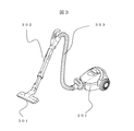
図3は本発明の実施形態の一例に係る電気掃除機の全体外観図である。
吸口301から吸引された塵埃は延長管302、ホース303を通り掃除機本体201に集塵される。
FIG. 3 is an overall external view of a vacuum cleaner according to an example of the embodiment of the present invention.
Dust sucked from the
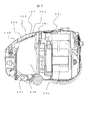
図2は本発明の実施形態の一例に係る電気掃除機の本体断面図である。掃除機本体201の内部には上面が開口した集塵室202、電動送風機203を設けており、集塵室202には吸引した塵埃を集塵する集塵フィルター204が装着されている。集塵フィルター204は厚紙等の硬質材料からなる口板205と、この口板205に接着された袋部材206から構成され、口板205によって集塵室202に取付けられている。
FIG. 2 is a cross-sectional view of the main body of the vacuum cleaner according to an example of the embodiment of the present invention. Inside the vacuum cleaner
集塵室202上部には集塵フィルター204を取出し可能に開閉可能な蓋体101を設けている。更に蓋体101の内側(集塵室側)には吸引風を清潔に保つためのフィルター102を備えフィルター保持部材103で蓋体101に取付けている。
A
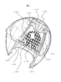
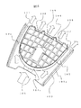
図1は本発明の実施形態の一例に係る電気掃除機の蓋体の図(蓋体を内側から見た図)である。フィルター102はフィルター保持部材103の内側にあるフィルターの収納部104に収納され、その外周には集塵フィルター204(図示せず)が膨らんでも蓋体101内部と集塵フィルター204の間で風の流れる流路が無くならないように流路空間105を設けている。流路空間の入口106はフィルター102の前方に大きく開口して電動送風機204(図示せず)への風の流れを確保している。図示した矢印の如く、吸引風はフィルター保持部材103の格子状の穴から入りフィルター収納部の排気口108から電動送風機へ導かれる。これにより、蓋体101内部に設けたフィルター102へ積極的に風が流れて、塵埃を通過して集塵フィルターから出た吸引風を清潔にすることができる。同時に流路空間の入口106から流路空間105へ常に吸引風が導かれ、集塵フィルターが膨らみ蓋体101内部へはりつくことによる、吸引流路現象が原因の吸引力の低下を防ぐことができる。
図5は本発明の実施形態の一例に係る電気掃除機のフィルター保持部材の図である。フィルター保持部材103には、その両側に蓋体101側に向かって突出した流路壁105aが形成されている。また、フィルター収納部104の外周には、フィルター収納部104を覆うと共に蓋体101側に向かって突出したフィルター収納壁104aが形成されている。そして、フィルター収納壁104aと流路壁105aとが蓋体101の内側と接することにより、流路空間105が形成される。
FIG. 5 is a view of a filter holding member of a vacuum cleaner according to an example of the embodiment of the present invention. The
流路空間105の入口106はフィルターの収納部104の前方に大きく開口して比較的大きく断面積を確保しているが、流路空間105はフィルターの収納部104の外周に位置し、本実施の形態では流路を2分岐している。流路空間の排気口107はフィルター102(図示せず)の後方に位置し、流路空間の入口106に対して断面積が小さいが複数個設けることにより電動送風機204(図示せず)への風の流れを確保している。これにより、集塵室内に集塵可能な塵埃の容積を比較的減らすこと無く、吸引力の低下を防ぐとともに積極的にフィルターに風を流すことができるので吸引風を清潔に保つことができる。
The
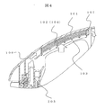
図4は本発明の実施形態の一例に係るフィルター保持部材周辺の部分拡大図である。集塵フィルター204の口板205は流路空間の入口106よりも電動送風機側(図示せず)へ位置しているので膨らんだ集塵フィルターによって流路空間の入口106が塞がれることを防止している。また、流路空間の入口106から流路空間の排気口107までの長さ、つまり流路空間105の長さはフィルター収納部104よりも風の流れる方向(図示の矢印方向)に対して長く設けているので膨らんだ集塵フィルターによって流路空間が塞がれることを防止している。
FIG. 4 is a partially enlarged view around the filter holding member according to an example of the embodiment of the present invention. Since the
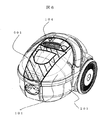
図6は本発明の実施形態の一例に係る電気掃除機の本体外観図である。掃除機本体201に設けた蓋体101は略透明部材で成形して意匠性を向上させている。また、流路空間(図示せず)の外側に位置する部分に不透明部材601を設けているので外から流路空間を隠すことが可能で外観を損うことが無い。この不透明部材601の代わりに斜線部分を塗装などで覆うことも可能である。さらに、フィルター収納部分104の外側を不透明部材で覆っていないので、フィルターに紫外線などの外光が当たるため、外光を利用して活性化するフィルターなどの効果が有効に活用できる。
FIG. 6 is an external view of a main body of a vacuum cleaner according to an example of the embodiment of the present invention. The
101…蓋体、102…フィルター、103…フィルター保持部材、104…収納部、105…流路空間、106…流路空間の入口、107…流路空間の排気口、108…フィルター収納部の排気口、201…掃除機本体、202…集塵室、203…電動送風機、204…集塵フィルター、205…口板、301…吸口、302…延長管、303…ホース、601…不透明部材。
DESCRIPTION OF
Claims (5)
前記保持部材は、前記フィルターを収納するフィルター収納部と、該フィルター収納部の外周に設けられた流路空間とを有することを特徴とする電気掃除機。 Vacuum cleaner body with built-in dust collection chamber and electric blower with upper surface opened, dust collection filter mounted in dust collection chamber, lid body covering upper surface opening of dust collection chamber, and dust collection of the lid body A filter provided on the chamber side, and a holding member provided on the dust collection chamber side of the lid for holding the filter,
The vacuum cleaner according to claim 1, wherein the holding member includes a filter storage portion for storing the filter, and a flow path space provided on an outer periphery of the filter storage portion.
前記集塵フィルターは、口板と、該口板に取付けられた袋部材とから構成され、
前記口板は前記流路空間の入口よりも電動送風機側に設けたことを特徴とする電気掃除機 In claim 1,
The dust collecting filter is composed of a mouth plate and a bag member attached to the mouth plate,
The vacuum cleaner, wherein the mouth plate is provided closer to the electric blower than the inlet of the flow path space
前記流路空間の長さを前記フィルター収納部よりも風の流れる方向に対して長くしたことを特徴とする電気掃除機。 In claim 1 or 2,
The vacuum cleaner characterized in that the length of the flow path space is made longer than the filter housing part in the direction in which the air flows.
前記流路空間から吸引風が排出する流路空間の排気口を複数個設けたことを特徴とする電気掃除機。 In any one of Claims 1 to 3,
An electric vacuum cleaner comprising a plurality of air outlets of a channel space through which suction air is discharged from the channel space.
前記蓋体を略透明材料で成形し、前記蓋体の外側に不透明部材を設け、
前記不透明部材を前記流路空間に沿った形状にしたことを特徴とする電気掃除機。
In any one of Claims 1 thru | or 4,
The lid is formed of a substantially transparent material, and an opaque member is provided outside the lid,
A vacuum cleaner characterized in that the opaque member is shaped along the flow path space.
Priority Applications (1)
| Application Number | Priority Date | Filing Date | Title |
|---|---|---|---|
| JP2004120988A JP2005296531A (en) | 2004-04-16 | 2004-04-16 | Electric vacuum cleaner |
Applications Claiming Priority (1)
| Application Number | Priority Date | Filing Date | Title |
|---|---|---|---|
| JP2004120988A JP2005296531A (en) | 2004-04-16 | 2004-04-16 | Electric vacuum cleaner |
Publications (1)
| Publication Number | Publication Date |
|---|---|
| JP2005296531A true JP2005296531A (en) | 2005-10-27 |
Family
ID=35328772
Family Applications (1)
| Application Number | Title | Priority Date | Filing Date |
|---|---|---|---|
| JP2004120988A Pending JP2005296531A (en) | 2004-04-16 | 2004-04-16 | Electric vacuum cleaner |
Country Status (1)
| Country | Link |
|---|---|
| JP (1) | JP2005296531A (en) |
Cited By (4)
| Publication number | Priority date | Publication date | Assignee | Title |
|---|---|---|---|---|
| CN102188192A (en) * | 2010-03-10 | 2011-09-21 | 松下电器产业株式会社 | Electric dust collector |
| JP2011234849A (en) * | 2010-05-10 | 2011-11-24 | Mitsubishi Electric Corp | Vacuum cleaner |
| CN103188977A (en) * | 2010-09-08 | 2013-07-03 | 欧罗菲利特斯控股公司 | Vacuum-cleaning apparatus with vacuum-cleaner unit and filter bag |
| JP2014144167A (en) * | 2013-01-30 | 2014-08-14 | Mitsubishi Electric Corp | Vacuum cleaner |
-
2004
- 2004-04-16 JP JP2004120988A patent/JP2005296531A/en active Pending
Cited By (9)
| Publication number | Priority date | Publication date | Assignee | Title |
|---|---|---|---|---|
| CN102188192A (en) * | 2010-03-10 | 2011-09-21 | 松下电器产业株式会社 | Electric dust collector |
| JP2011234849A (en) * | 2010-05-10 | 2011-11-24 | Mitsubishi Electric Corp | Vacuum cleaner |
| CN103188977A (en) * | 2010-09-08 | 2013-07-03 | 欧罗菲利特斯控股公司 | Vacuum-cleaning apparatus with vacuum-cleaner unit and filter bag |
| JP2013539397A (en) * | 2010-09-08 | 2013-10-24 | ユーロフィルターズ ホールディング エヌ.ブイ. | Vacuum cleaner unit and vacuum cleaner with filter bag |
| JP2015144847A (en) * | 2010-09-08 | 2015-08-13 | ユーロフィルターズ ホールディング エヌ.ブイ. | Vacuum-cleaning apparatus with vacuum-cleaner unit and filter bag |
| US9554681B2 (en) | 2010-09-08 | 2017-01-31 | Eurofilters Holding N.V. | Vacuum-cleaning apparatus with vacuum-cleaner unit and filter bag |
| CN103188977B (en) * | 2010-09-08 | 2017-08-25 | 欧罗菲利特斯控股公司 | Vacuum cleaning apparatus with vacuum cleaning unit and filter bag |
| JP2014144167A (en) * | 2013-01-30 | 2014-08-14 | Mitsubishi Electric Corp | Vacuum cleaner |
| TWI552711B (en) * | 2013-01-30 | 2016-10-11 | 三菱電機股份有限公司 | Electric vacuum cleaner |
Similar Documents
| Publication | Publication Date | Title |
|---|---|---|
| RU2304424C1 (en) | Vacuum cleaner (versions) | |
| KR100471142B1 (en) | Cyclone dust collecting device and vacuum cleaner having the same | |
| EP1535560A3 (en) | Dust-collecting device and vacuum cleaner for both wet and dry cleaning using the same | |
| KR20090074588A (en) | Dust collector of vacuum cleaner | |
| CN107348894A (en) | a surface cleaner | |
| JP2005296531A (en) | Electric vacuum cleaner | |
| CN216854610U (en) | Automatically cleaning collection dirt seat and dust collecting system | |
| CN116636771A (en) | Noise reduction device and low noise vacuum cleaner | |
| KR102206326B1 (en) | Humidifacation type air cleaner | |
| JP5188413B2 (en) | Electric vacuum cleaner | |
| KR100730944B1 (en) | Exhaust flow path structure of vacuum cleaner | |
| JP4557783B2 (en) | Vacuum cleaner | |
| ES2259510B2 (en) | AIR DISCHARGE DEVICE FOR A VACUUM CLEANER. | |
| JP4814062B2 (en) | Vacuum cleaner | |
| RU2380025C2 (en) | Construction of vacuum-cleaner main case | |
| CN216293939U (en) | Dust separation module for cleaning machine and cleaning machine | |
| JP2006204549A (en) | Electric vacuum cleaner | |
| CN216854607U (en) | Automatically cleaning collection dirt seat and dust collecting system | |
| CN216293941U (en) | Dust separation module for cleaning machine and cleaning machine | |
| CN217066233U (en) | Rod body mechanism and cleaning equipment | |
| JP2008022932A (en) | Vacuum cleaner | |
| JP6106509B2 (en) | Electric vacuum cleaner | |
| JP4912252B2 (en) | Floor brush and vacuum cleaner | |
| JP5040453B2 (en) | Dust collector and electric vacuum cleaner using the same | |
| JP2009072401A (en) | Electric vacuum cleaner |
Legal Events
| Date | Code | Title | Description |
|---|---|---|---|
| RD04 | Notification of resignation of power of attorney |
Free format text: JAPANESE INTERMEDIATE CODE: A7424 Effective date: 20060509 |