JP2005296491A - Electric rice cooker - Google Patents
Electric rice cooker Download PDFInfo
- Publication number
- JP2005296491A JP2005296491A JP2004120115A JP2004120115A JP2005296491A JP 2005296491 A JP2005296491 A JP 2005296491A JP 2004120115 A JP2004120115 A JP 2004120115A JP 2004120115 A JP2004120115 A JP 2004120115A JP 2005296491 A JP2005296491 A JP 2005296491A
- Authority
- JP
- Japan
- Prior art keywords
- power supply
- igbt
- supply voltage
- zero
- zero cross
- Prior art date
- Legal status (The legal status is an assumption and is not a legal conclusion. Google has not performed a legal analysis and makes no representation as to the accuracy of the status listed.)
- Pending
Links
Images

Landscapes
- Cookers (AREA)
Abstract
【課題】 所定レベル以下の電源電圧低下時から、電源電圧正常レベルへの復帰時におけるIGBTの損傷を回避する。
【解決手段】 ワークコイルを駆動する半導体スイッチング素子であるIGBTと電源電圧のゼロクロスを検出するゼロクロス検知回路とを備え、上記IGBTのゲートに印加される上記ゼロクロス検知回路からのゼロクロス信号に応じてワークコイルに電流を流して内鍋を加熱するようにしてなる電気炊飯器において、ゼロクロス検知回路に低電圧判定機能を付加し、電源電圧の周期に応じて設定された所定の時間内に、上記ゼロクロス検知回路により電源電圧のゼロクロスが検知されなかったときは、所定レベル以下の低電圧状態であると判定して、IGBTの駆動を停止させるようにした。
【選択図】 図3
PROBLEM TO BE SOLVED: To avoid damage to an IGBT when a power supply voltage drops below a predetermined level and then returns to a normal power supply voltage level.
An IGBT, which is a semiconductor switching element that drives a work coil, and a zero-cross detection circuit that detects a zero-cross of a power supply voltage, and a workpiece according to a zero-cross signal from the zero-cross detection circuit applied to the gate of the IGBT. In an electric rice cooker that heats the inner pot by passing an electric current through the coil, a zero voltage detection function is added to the zero cross detection circuit, and the zero cross is performed within a predetermined time set according to the cycle of the power supply voltage. When the detection circuit did not detect the zero crossing of the power supply voltage, it was determined that the low voltage state was below a predetermined level, and the driving of the IGBT was stopped.
[Selection] Figure 3
Description
本願発明は、低電圧時への対応機能を備えた電気炊飯器に関するものである。 The present invention relates to an electric rice cooker having a function to cope with a low voltage.
例えば半導体スイッチング素子であるIGBTを備えて内鍋加熱用のワークコイルを駆動制御する電磁誘導加熱式の電気炊飯器の場合、電源電圧のゼロクロスタイミングを検出するゼロクロス検知回路を備え、同ゼロクロス検知回路で検知されたゼロクロス信号を基準として上記IGBTをON,OFFし、上記ワークコイルの駆動状態、駆動出力を制御するようになっている(例えば特許文献1参照)。 For example, in the case of an electromagnetic induction heating-type electric rice cooker that includes an IGBT, which is a semiconductor switching element, and drives and controls a work coil for heating an inner pot, it is equipped with a zero-cross detection circuit that detects the zero-cross timing of the power supply voltage. The IGBT is turned on and off with reference to the zero-cross signal detected in step 1, and the drive state and drive output of the work coil are controlled (see, for example, Patent Document 1).
つまり、電磁誘導加熱式の電気炊飯器は、ワークコイルへの電流の開閉手段であるIGBTのゲートに印加される電源電圧のゼロクロス信号に応じて、ワークコイルに対し、炊飯工程に応じた適切な大きさの電流を流して内鍋を加熱するようになっている。 In other words, the electromagnetic induction heating type electric rice cooker is suitable for the work coil according to the rice cooking process according to the zero cross signal of the power supply voltage applied to the gate of the IGBT which is a means for opening and closing the current to the work coil. The inner pot is heated by passing a current of magnitude.
そして、このような構成の場合、何らかの事情で電源電圧が低下すると、上記加熱出力の制御機能を有するマイコン制御ユニットは、上記ワークコイル出力の低下を補うべく、その駆動電流を増大させる方向にIGBTの動作状態を制御する。その結果、内鍋加熱出力の低下が最少限に抑制され、可及的に適切な炊飯機能が維持される。 In the case of such a configuration, when the power supply voltage decreases for some reason, the microcomputer control unit having the heating output control function increases the drive current in the direction of increasing the drive current to compensate for the decrease in the work coil output. Control the operating state of As a result, a decrease in the inner pot heating output is suppressed to a minimum, and an appropriate rice cooking function is maintained as much as possible.
ところが、以上のような構成の場合、同電源電圧の低下が所定レベル以下(例えば10〜20V)であって、その後、同電源電圧が正常なレベル(90〜100V)に復帰したような場合、その直後のサイクルでは過大な電流がIGBTに流され、IGBTを損傷する恐れがある。 However, in the case of the configuration as described above, when the drop in the power supply voltage is below a predetermined level (for example, 10 to 20 V) and then the power supply voltage returns to a normal level (90 to 100 V), In the cycle immediately after that, an excessive current flows through the IGBT, which may damage the IGBT.
本願発明は、このような問題を解決するためになされたもので、上述のゼロクロス検知回路に低電圧判定機能を付加し、例えば電源電圧の周期に応じて設定された所定の時間内に、上記ゼロクロス検知回路により電源電圧のゼロクロスが検知されなかったときは、上記所定レベル以下の低電圧状態であると判定し、半導体スイッチング素子IGBTの駆動を停止させることができるようにした電気炊飯器提供することを目的とするものである。 The present invention has been made to solve such a problem. A low voltage determination function is added to the above-described zero-crossing detection circuit, and the above-described invention is performed within a predetermined time set according to the cycle of the power supply voltage, for example. Provided is an electric rice cooker in which when the zero cross of the power supply voltage is not detected by the zero cross detection circuit, it is determined that the low voltage state is equal to or lower than the predetermined level, and the driving of the semiconductor switching element IGBT can be stopped. It is for the purpose.
本願発明は、上記の目的を達成するために、次のような課題解決手段を備えて構成されている。 In order to achieve the above object, the present invention is configured with the following problem solving means.
(1) 第1の課題解決手段
この発明の第1の課題解決手段は、ワークコイルを駆動する半導体スイッチング素子IGBTと電源電圧のゼロクロスタイミングを検出するゼロクロス検知回路とを備え、上記IGBTのゲートに印加される上記ゼロクロス検知回路からのゼロクロス信号に応じてワークコイルに電流を流して内鍋を加熱する電気炊飯器において、上記ゼロクロス検知回路に低電圧判定機能を付加し、電源電圧の周期に応じて設定された所定の時間内に、上記ゼロクロス検知回路により上記電源電圧のゼロクロスが検知されなかったときは、所定レベル以下の低電圧状態であると判定して、上記IGBTの駆動を停止させるようにしたことを特徴としている。
(1) First Problem Solving Means The first problem solving means of the present invention comprises a semiconductor switching element IGBT for driving a work coil and a zero cross detection circuit for detecting a zero cross timing of a power supply voltage, and is provided at the gate of the IGBT. In the electric rice cooker that heats the inner pot by supplying current to the work coil according to the zero cross signal from the applied zero cross detection circuit, a low voltage determination function is added to the zero cross detection circuit, and according to the cycle of the power supply voltage If the zero cross of the power supply voltage is not detected by the zero cross detection circuit within the predetermined time set in the above, it is determined that the low voltage state is equal to or lower than a predetermined level, and the driving of the IGBT is stopped. It is characterized by that.
このように、ゼロクロス検知回路に低電圧判定機能を付加し、電源電圧の周期に応じて設定された所定の時間内に、ゼロクロス検知回路により電源電圧のゼロクロスが検知されなかったときは、所定レベル以下の低電圧状態であると判定して、IGBTの駆動を停止させるようにすると、その後、電源電圧が正常なレベル値に復帰したような時にも、IGBTに過大な電流が流れてIGBTを損傷するような恐れがなくなる。 In this way, a low voltage determination function is added to the zero cross detection circuit, and when the zero cross of the power supply voltage is not detected by the zero cross detection circuit within a predetermined time set according to the cycle of the power supply voltage, a predetermined level is set. If the IGBT is determined to be in the following low voltage state and the drive of the IGBT is stopped, an excessive current flows through the IGBT and damages the IGBT even when the power supply voltage returns to a normal level after that. No fear of doing.
(2) 第2の課題解決手段
この発明の第2の課題解決手段は、上記第1の課題解決手段の構成において、IGBTの駆動の停止は、少なくとも1回ゼロクロスが検知されなかった場合になされるようになっていることを特徴としている。
(2) Second Problem Solving Means According to a second problem solving means of the present invention, in the configuration of the first problem solving means, the drive of the IGBT is stopped when zero crossing is not detected at least once. It is characterized by becoming.
このように、少なくとも1回でもゼロクロスが検知されなかった場合に、IGBTの駆動を停止させるようにすると、確実にIGBTの保護を図ることができるようになる。 As described above, when the driving of the IGBT is stopped when the zero cross is not detected at least once, the IGBT can be surely protected.
(3) 第3の課題解決手段
この発明の第3の課題解決手段は、上記第1又は第2の課題解決手段の構成において、所定レベル以下の低電圧状態であることの判定は、IGBTのゲート電源電圧側に定電圧ダイオードを設け、該定電圧ダイオードによって判定基準となる最低電圧を設定することによりなされるようになっていることを特徴としている。
(3) Third Problem Solving Means According to a third problem solving means of the present invention, in the configuration of the first or second problem solving means, the determination that the low voltage state is equal to or lower than a predetermined level is determined by the IGBT. It is characterized in that a constant voltage diode is provided on the gate power supply voltage side and a minimum voltage as a determination reference is set by the constant voltage diode.
このように、IGBTのゲート電源電圧側に定電圧ダイオードを設け、該定電圧ダイオードによって判定基準となる最低電圧を設定して、それを基に現在の電源電圧と比較して、電源電圧が上記所定レベル以下となったことを判定するようにすると、定電圧ダイオードを設けるだけの極めて簡単かつ低コストな構成で、上記第1,第2の課題解決手段の作用効果を実現することができる。 In this way, a constant voltage diode is provided on the gate power supply voltage side of the IGBT, and a minimum voltage as a determination reference is set by the constant voltage diode, and the power supply voltage is compared with the current power supply voltage based on the minimum voltage. If it is determined that the level is equal to or lower than the predetermined level, the effects of the first and second problem solving means can be realized with an extremely simple and low-cost configuration in which only a constant voltage diode is provided.
(4) 第4の課題解決手段
この発明の第4の課題解決手段は、上記第1,第2又は第3の課題解決手段の構成において、IGBTの駆動状態の復帰は、一旦仮復帰状態に維持し、その後完全復帰状態に復帰させるようにしたことを特徴としている。
(4) Fourth Problem Solving Means According to a fourth problem solving means of the present invention, in the configuration of the first, second or third problem solving means, the drive state of the IGBT is temporarily returned to the temporary return state. It is characterized in that it is maintained and then returned to the complete return state.
このように、IGBTの駆動状態を元の状態に復帰させるに際し、一旦仮復帰状態に維持し、その後完全復帰状態に復帰させるようにすると、一旦ゼロクロスを検知した後、例えばIGBTのゲート信号用電源の放電時間を考慮した所定の待ち時間を有して本来の駆動制御状態に復帰させることができるので、信頼性を向上させることができる。 As described above, when the drive state of the IGBT is returned to the original state, once it is maintained in the temporary return state and then returned to the complete return state, once the zero cross is detected, for example, the power supply for the gate signal of the IGBT Therefore, it is possible to return to the original drive control state with a predetermined waiting time in consideration of the discharge time, and thus the reliability can be improved.
(5) 第5の課題解決手段
この発明の第5の課題解決手段は、上記第4の課題解決手段の構成において、仮復帰は電源電圧のゼロクロスを複数回検知した場合に行ない、完全復帰は仮復帰した後、さらに所定時間経過した後に行うようにしたことを特徴としている。
(5) Fifth Problem Solving Means According to a fifth problem solving means of the present invention, in the configuration of the fourth problem solving means, temporary restoration is performed when a zero cross of the power supply voltage is detected a plurality of times, and complete restoration is performed. It is characterized in that it is performed after a predetermined time has elapsed after the temporary return.
このように、IGBTを駆動状態に復帰させるに際し、上述の仮復帰は電源電圧のゼロクロスを複数回検知した場合に行ない、完全復帰は仮復帰した後、さらに所定時間経過した後に行うようにすると、一旦ゼロクロスを検知した後、IGBTのゲート信号用電源の放電時間を考慮した所定の待ち時間を有して本来の駆動制御状態に復帰させることができるので、より信頼性を向上させることができる。 As described above, when the IGBT is returned to the driving state, the temporary return described above is performed when the zero crossing of the power supply voltage is detected a plurality of times, and the complete return is performed after a predetermined time has elapsed after the temporary return. Once the zero cross is detected, it is possible to return to the original drive control state with a predetermined waiting time in consideration of the discharge time of the IGBT gate signal power supply, so that the reliability can be further improved.
以上の結果、本願発明によると、停電時等のみでなく所定レベル以下への電源電圧低下時にも、確実にIGBTを保護することができるようになり、製品の信頼性を向上させることができる。 As a result, according to the present invention, the IGBT can be reliably protected not only at the time of a power failure or the like but also when the power supply voltage drops below a predetermined level, and the reliability of the product can be improved.
図1〜図4は、本願発明の最良の実施の形態に係る電気加熱調理器としてのマイコン式電気炊飯器の炊飯器本体およびその制御回路部分の構成、並びに同電気炊飯器の低電圧時における対応制御の内容をそれぞれ示している。 1 to 4 show the configuration of a rice cooker body and its control circuit part of a microcomputer-type electric rice cooker as an electric heating cooker according to the best mode of the present invention, and the electric rice cooker at a low voltage. The contents of the corresponding control are shown.
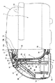
(炊飯器本体部分の基本構成・・・図1、図2参照)
すなわち、先ず該電気炊飯器の炊飯器本体は、例えば図1に示すように、内部に誘起されるうず電流によって自己発熱が可能な例えばステンレス鋼板等の磁性金属板よりなる内鍋(飯器ないし保温容器)3と、該内鍋3を任意にセットし得るように形成された合成樹脂製の有底筒状の保護枠(内ケース)4と、該保護枠(内ケース)4を保持する外部筺体である有底筒状の外ケース1と、該外ケース1と上記保護枠(内ケース)4とを一体化して形成された炊飯器器体Aの上部に開閉可能に設けられた蓋ユニット(蓋)2とから構成されている。
(Basic structure of the rice cooker body: see Figs. 1 and 2)
That is, first, the rice cooker body of the electric rice cooker has, for example, an inner pot made of a magnetic metal plate such as a stainless steel plate capable of self-heating by an eddy current induced therein, as shown in FIG. A heat insulating container) 3, a synthetic resin bottomed cylindrical protective frame (inner case) 4 formed so that the inner pot 3 can be arbitrarily set, and the protective frame (inner case) 4 are held. A lid provided on the upper part of a rice cooker body A formed by integrating the outer case 1 and the outer case 1 and the protective frame (inner case) 4 as an outer casing and a bottomed cylindrical outer case 1. The unit (lid) 2 is constituted.
上記保護枠(内ケース)4の底壁部(底部)4aの下方側にはコイル台7が設けられ、その上部には、フェライトコアを介し、上記内鍋3の底壁部(底部)3aの中央部と側方部の各位置に対応して各々リッツ線が同心状に巻成されたワークコイルCが、それぞれ内鍋3の底壁部3aの中央から側部に到る略全体を包み込むように設けられており、それらにより通電時には内鍋3の略全体にうず電流を誘起して、その全体を略均一に加熱するようになっている。そして、該ワークコイルCの一端は、後述するように整流回路および平滑回路を介したワークコイル駆動回路の電源ラインに、また他端は同回路中のIGBT(パワートランジスタ)にそれぞれ接続されている。
A coil base 7 is provided below the bottom wall portion (bottom portion) 4a of the protective frame (inner case) 4, and the bottom wall portion (bottom portion) 3a of the inner pot 3 is interposed on the upper portion thereof via a ferrite core. Corresponding to each position of the center part and the side part of each, the work coil C by which the litz wire was each concentrically wound is substantially the whole from the center of the
また、上記側壁部3bの上方部には、保温時において加熱手段として機能する保温ヒータH1が設けられており、保温時において上記内鍋3の全体を有効かつ均一に加熱するようになっている。また、上記肩部材11の肩部内周側には、肩ヒータH2が設けられている。
Above part of the
また、上記保護枠(内ケース)4およびコイル台7の前方部側には、上記ワークコイルC、保温ヒータH1、肩ヒータH2等を駆動制御するに必要な電源電圧整流用のダイオードブリッジよりなる整流回路、平滑回路、IGBT、ヒータ駆動回路、マイコン制御ユニットを備えた制御基板6Aおよび制御基板収納ボックス5Aが上下立設状態で設けられている。
A diode bridge for power supply voltage rectification necessary for driving and controlling the work coil C, the heat retaining heater H 1 , the shoulder heater H 2 and the like is provided on the front side of the protective frame (inner case) 4 and the coil base 7. A
また上記外ケース1は、例えば合成樹脂材で形成された上下方向に筒状のカバー部材1aと、該カバー部材1aの上端部に結合された合成樹脂製の肩部材11と、上記カバー部材1aの下端部に一体化された合成樹脂製の底部材1bとからなり、かつ上記保護枠(内ケース)4の底壁部4aとの間に所定の広さの断熱および通風空間部を形成した全体として有底の筒状体に構成されている。そして、該外ケース1の前面部上方には、操作パネル部20が設けられている。。
The outer case 1 includes, for example, a
さらに、同操作パネル部20の内側部分(裏側空間)には、上記制御基板6Aの上端側位置から斜め前方に下降する格好で、例えばマイコン基板6Bが傾斜設置されている。
Further, in the inner part (back side space) of the
さらに、図示はしないが、上記保護枠(内ケース)4下方側のコイル台7の中央部には、上下方向に同心状に貫通したセンタセンサ収納空間部が形成されており、該センタセンサ収納空間部中に上下方向に昇降自在な状態で、かつ常時コイルスプリングにより上方に上昇付勢された状態で、例えば図2に示す内鍋温度検知センサSおよび内鍋検知スイッチLSを備えたセンタセンサが設けられている。 Further, although not shown in the figure, a center sensor storage space portion that is concentrically penetrated in the vertical direction is formed in the central portion of the coil base 7 below the protective frame (inner case) 4. A center sensor provided with, for example, an inner pot temperature detection sensor S and an inner pot detection switch LS shown in FIG. 2 in a state where it can be moved up and down in the vertical direction and is always upwardly biased by a coil spring. Is provided.
一方、符号2は蓋ユニットであり、該蓋ユニット2は、その外周面を構成する合成樹脂製の外カバー12と、該外カバー12と内枠14との間に設けられた金属製の断熱構造体13と、該断熱構造体13の内側にパッキン17を介して設けられた金属製の内カバー15と、該内カバー15の下方に設けられた金属製の放熱板16とによって内側が中空の断熱構造体に形成されている。また、上記断熱構造体13は上下2枚の金属板13a,13bを閉断面構造に対向させて一体化することにより形成されている。
On the other hand, reference numeral 2 denotes a lid unit. The lid unit 2 is composed of an
この蓋ユニット2は、上記外ケース1上部の肩部材11に対してヒンジ機構を介して回動自在に取付けられており、その開放端側には、該蓋ユニット2の所定位置に係合して該蓋ユニット2の上下方向への開閉を行うロック機構18が設けられている。
The lid unit 2 is rotatably attached to the
したがって、該構成では、先ず炊飯時には、上記内鍋3は、上記ワークコイルCの駆動によりその底壁部3aから側壁部3bにかけて略全体が均一に発熱し、例えば内鍋3内の水に浸された飯米が断熱部として作用する吸水工程などにおいても内鍋3の上部側をもムラなく加熱して略全体に均一な吸水性能を可能にするとともに、炊飯量が多い時などにも内鍋3の全体を略均一に加熱して加熱ムラなく効率良く炊き上げることができる。また、沸騰工程以降の水分がなくなった状態における内鍋3の底壁部3aの局部的な熱の集中を防止して焦げ付きの発生を防止することができる。
Therefore, in this configuration, at the time of rice cooking, the inner pan 3 generates heat substantially uniformly from the
次に、保温時には、上記内鍋3の側壁部3bに対応して設けられた上記保温ヒータH1および蓋ユニット2の内カバー15に当接するように設けられた肩ヒータH2の駆動により、内鍋3の底壁部3aから側壁部3bおよび上方側開口部の全体が適切な加熱量で略均一に加熱されて加熱ムラのない保温が実現される。
Next, at the time of heat retention, by driving the heat retaining heater H 1 provided corresponding to the
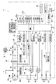
(炊飯器本体側制御回路部分の構成・・・図2、図3参照)
次に、図2、図3は上述のように構成された炊飯器本体側のマイコン制御ユニットを中心とする制御回路部分の構成を示す。
(Composition of the rice cooker body side control circuit part: see FIGS. 2 and 3)
Next, FIG. 2, FIG. 3 shows the structure of the control circuit part centering on the microcomputer control unit by the side of the rice cooker main body comprised as mentioned above.
図中、符号32がマイコン制御ユニット(CPU)であり、該マイコン制御ユニット32はマイクロコンピュータを中心として構成され、例えば内鍋3の温度検知回路部、ワークコイル駆動制御回路部、停電等低電圧対応制御回路部(その構成および動作は後述・・・図3および図4参照)、内鍋3の検知回路部、発振回路部、リセット回路部、保温ヒータおよび肩ヒータ等駆動制御回路部、残時間設定表示制御回路部、ブザー報知部、電源回路部、バックアップ電源回路部、システム・時計等クロック発生回路部等を各々有して構成されている。
In the figure,
そして、先ず上記内鍋3の底壁部3a側センタセンサ部の内鍋温度検知センサS、内鍋検知スイッチLSに対応して設けられた温度検知回路43および鍋検知回路44には、例えば上記内鍋温度検知センサSによる内鍋3の底壁部3aの温度検知信号、内鍋検知スイッチLSによる鍋検知信号がそれぞれ入力されるようになっている。
And first, the temperature detection circuit 43 and the pot detection circuit 44 provided corresponding to the inner pot temperature detection sensor S, the inner pot detection switch LS of the
また、上記ワークコイル駆動制御回路部は、例えばパルス幅変調回路41、同期トリガー回路40、IGBT駆動回路42、IGBT37、共振コンデンサ38、整流回路35、平滑コンデンサ36等によって形成されている。そして、上記マイコン制御ユニット32のワークコイル駆動制御回路部により、上記パルス幅変調回路41を制御することにより、例えば炊飯工程に応じて上記ワークコイルCの出力値および同出力値でのONデューティー比(例えばn秒/16秒)をそれぞれ適切に変えることによって、炊飯又は蒸し加熱工程の各工程における内鍋3の加熱温度と加熱パターンを炊飯量を考慮して適切に可変コントロールし、均一な吸水作用と加熱ムラのない御飯の炊き上げ又は蒸し加熱調理を実現するための適切な出力制御が行われるようになっている。
The work coil drive control circuit unit is formed by, for example, a pulse
整流回路35は、充電部品であるノイズカット用コンデンサ24、電源ヒューズFを介して電源プラグ30b.30b部分に接続されている。該電源プラグ30b.30b部分には、図示しない差し込みプラグを介して一端側がAC電源(AC電源コンセント)30に接続された電源コードの他端側挿入プラグ30a.30aが着脱可能に接続され、AC100(V)の電源電圧が印加されるようになっている。
The
そして、この印加電源電圧は、同電源プラグ30b.30bから電源ヒューズF、ノイズカット用コンデンサ24を経て上記整流回路35に供給されて整流されるが、その電源ライン途中には、例えば図3に示すようなフォトカプラPCおよびスイッチングトランジスタQよりなるゼロクロス検知回路29cが設けられており、AC電源電圧Vacのゼロクロスタイミング(図4の(a)参照)を検出して、同ゼロクロスタイミングに対応したゼロクロス信号Zc(図4の(b)参照)をマイコン制御ユニット32の停電等低電圧対応制御回路部その他に入力するようになっている。整流回路35には、また電流後の電圧レベルを検知する電圧検知回路29Bが設けられている。
The applied power supply voltage is the same as the
また、上記AC電源ライン間には、第1のフォトトライアックPT1を介して保温ヒータH1が、また第2のフォトトライアックPT2を介して肩ヒータH2が接続されている。 Further, between the AC power lines, a heat retaining heater H 1 is connected via a first phototriac PT 1 and a shoulder heater H 2 is connected via a second phototriac PT 2 .
また上記マイコン制御ユニット32の保温ヒータ駆動制御回路部および肩ヒータ駆動制御回路部により、それぞれ保温ヒータ駆動回路33および肩ヒータ駆動回路34を作動させて、上記第1,第2のフォトトライアックPT1,PT2をON,OFF制御(トリガー)することにより、例えば保温又は炊飯、蒸し加熱工程に応じて上記保温ヒータH1、肩ヒータH2の出力値、および同出力値でのONデューティー比(例えばn秒/16秒)をそれぞれ適切に変えることによって、保温又は炊飯、蒸し加熱工程の各工程における内鍋3の加熱温度と加熱パターンとを実際の炊飯量を考慮して適切に可変コントロールするための適切な出力制御が行われるようになっている。
The warming
また、符号22a〜22hは上述した操作パネル部20の各種入力スイッチであり、同スイッチの必要なものが適切に操作されると、上記マイコン制御ユニット32側の認識手段によってユーザーの指示内容が認識され、その認識内容に応じて所望の炊飯又は保温加熱パターンを設定して上記炊飯加熱制御手段又は蒸し保温加熱制御手段を適切に作動させて所望の炊飯又は保温を行うようになっている。
したがって、ユーザーは、同入力スイッチ22a〜22hを使用して炊飯又は保温、タイマー予約、予約時刻設定、白米又は玄米、早炊、おかゆ、かため又はやわらかめ、すしめし、炊き込み等の炊き分け、蒸し、通常保温又は低温保温等の各種の炊飯又は蒸し、保温機能の選択設定内容を入力すれば、それに対応した機能内容が当該マイコン制御ユニット32の上述した認識手段を介して炊飯又は蒸し、保温加熱パターン設定部に自動的に設定入力され、対応する炊飯又は蒸し、保温加熱制御が適切になされる。
Therefore, the user can use the input switches 22a to 22h to cook rice or keep warm, timer reservation, reservation time setting, white rice or brown rice, early cooking, rice porridge, kana or soft rice, sushi, rice cooking, etc. If various selections of steaming, normal warming or low temperature warming, etc. are input, the corresponding function content is cooked or steamed through the recognition means of the
さらに、符号25aは各種入力スイッチ22a〜22h操作時の操作音、炊飯完了を知らせるブザー報知音、何らかの異常を知らせる異常報知音等等を発する圧電ブザー、25は同圧電ブザー25aを駆動するブザー駆動回路、26はシステムクロック発生回路、27は時計クロック発生回路、28は停電時のマイコン制御ユニット32等バックアップ用の電源電池を備えたバックアップ電源回路、21は液晶表示部である。
Further,
上記バックアップ電源回路28は、AC電源(AC電源コンセント)30に接続されているAC電源コード他端の挿入プラグ30a.30aと炊飯器本体側電源プラグ30b.30bとの接続が外されるか、AC電源コード一端の差し込みプラグがAC電源(AC電源コンセント)30から抜かれるか、または停電その他の事情(製品検査工程でのラインエージングによる電圧変動)により、AC電源30からの電源の供給そのものが断たれたような時に、同停電に対応した所定の制御を行えるようにしている。
The
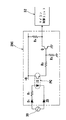
(低電圧に対応したIGBTの保護制御)
ところで、上述のゼロクロス検知回路29cは、AC電源30側半波整流回路部分が、半波整流用のダイオードD1、電流制限抵抗R1、フォトカプラPC用発光ダイオード、基準低電圧設定用の定電圧ダイオードZDからなり、それらの各々がAC電源30に対して直列に接続されている。
(Protection control of IGBT corresponding to low voltage)
By the way, in the above-described zero cross detection circuit 29c, the
またマイコン制御ユニット32側ゼロクロス信号出力回路部分は、上記フォトカプラPC用発光ダイオードに対応したフォトトランジスタ、分圧抵抗R2およびR3、スイッチングトランジスタQ、プルアップ抵抗R4からなり、フォトカプラPC用フォトトランジスタがONになった時に分圧抵抗R3に生じる電圧によってスイッチングトランジスタQがONになることにより、図4(b)のようなゼロクロス信号を出力してマイコン制御ユニット32の停電等低電圧対応制御回路部に入力する。
The
上記定電圧ダイオードZDのツェナー電圧Vzは、例えば上述したIGBT37の適切なゲート電圧VGを確保することができる範囲内(20〜70V)での最低の電圧値(20V)に設定されており、AC電源30側の電圧Vacの値が同Vzよりも大きい場合にはON動作してフォトカプラPCの発光ダイオードに電流を流して発光させ、上記受光部側フォトトランジスタ、スイッチングトランジスタQをONにしてマイコン制御ユニット32側に電源電圧Vac(図4(a))のゼロクロス検出信号Zc(図4(b))を入力するが、同電圧Vacの値がVzよりも小さくなると、OFFになって上記フォトカプラPCの発光ダイオード、スイッチングトランジスタQをOFFにし、マイコン制御ユニット32側に上記ゼロクロス検出信号Zcが出力されないようにする。
The Zener voltage Vz of the Zener diode ZD, for example is set to the lowest voltage value within a range capable of ensuring a proper gate voltage V G of the IGBT37 described above (20~70V) (20V), When the value of the voltage Vac on the
つまり、本実施の形態のゼロクロス検知回路29cでは、上記のようにAC電源30側に上記ツェナー電圧Vzの定電圧ダイオードZDがあることにより、単に停電によりAC電源30側の電圧Vacがゼロ(V)となったような時だけではなく、例えば当該電気炊飯器の製品検査工程におけるラインエージング上の供給電圧の変動などにより、停電ではないが電源電圧Vacが例えば20〜10(V)程度に低下したような時にも停電時と同様にゼロクロス検出信号Zcが出力されないようにすることができ、それに対応して、それら各場合共に上述のIGBT37をOFFにして、電源電圧Vacの正常な電圧値への復帰時に当該IGBT37に過大な電流が流されることを防止する。
That is, in the zero cross detection circuit 29c of the present embodiment, the voltage Vac on the
すなわち、本実施の形態のような電磁誘導加熱式の電気炊飯器では、上記IGBT37のゲートに印加される電源電圧Vac側のゼロクロス信号Zcに応じてワークコイルCに電流を流して内鍋3を加熱するようになっている。
That is, in the electromagnetic induction heating type rice cooker as in the present embodiment, the inner pot 3 is made to flow through the work coil C according to the zero cross signal Zc on the power supply voltage Vac side applied to the gate of the
そして、このような構成の場合、何らかの事情で電源電圧Vacが低下すると、加熱出力制御機能を有するマイコン制御ユニット32は、ワークコイル出力の低下を補うべく、その駆動電流を増大させる方向にIGBTの動作状態を制御する。その結果、内鍋加熱出力の低下が最少限に抑制され、可及的に適切な炊飯機能が維持される。
In such a configuration, when the power supply voltage Vac decreases for some reason, the
ところが、以上のような構成の場合、同電源電圧Vacの低下度合が所定レベル以上(例えば上述の20〜10(V)位まで)であって、その後、同電源電圧Vacが正常なレベル(90〜100(V))に復帰したような場合、その直後のサイクルでは過大な電流がIGBT37に流され、IGBT37を損傷する恐れがある。
However, in the case of the configuration as described above, the degree of decrease of the power supply voltage Vac is equal to or higher than a predetermined level (for example, up to the above 20 to 10 (V) level), and thereafter, the power supply voltage Vac is at a normal level (90 In the case of returning to ˜100 (V)), an excessive current flows in the
そこで、以上のように、ゼロクロス検知回路29cに定電圧ダイオードZDを設けることによって低電圧判定機能を付加し、電源電圧Vacの周期(50Hz/60Hz)に応じて設定された所定の時間内に、ゼロクロス検知回路29cにより電源電圧Vacのゼロクロスが検知されなかったときは、所定レベル以下の低電圧状態(20〜10V)であると判定し、IGBT37の駆動を停止させるようにすると、その後、電源電圧Vacが正常なレベル値(90〜100(V))に復帰したような時にも、IGBT37に過大な電流が流れてIGBT37を損傷するような恐れがなくなる。この場合、上記予じめ設定された時間より前のゼロクロス信号は無視する。
Therefore, as described above, the low voltage determination function is added by providing the constant voltage diode ZD in the zero cross detection circuit 29c, and within a predetermined time set according to the cycle (50 Hz / 60 Hz) of the power supply voltage Vac, When the zero cross of the power supply voltage Vac is not detected by the zero cross detection circuit 29c, it is determined that the low voltage state (20 to 10V) is equal to or lower than a predetermined level and the drive of the
またこのようにIGBT37のゲート電源電圧側に定電圧ダイオードZDを設け、該定電圧ダイオードZDによって判定基準となる最低電圧Vz(20V)を設定して、それを基に現在の電源電圧Vacと比較して、電源電圧Vacが上記所定レベル(20V)以下となったことを判定するようにすると、定電圧ダイオードZDを設けるだけの極めて簡単かつ低コストな構成で、上記の作用効果を実現することができる。
In addition, the constant voltage diode ZD is provided on the gate power supply voltage side of the
また、以上の構成において、上記条件によるIGBT37の駆動状態の停止は、少なくとも1回でも電源電圧Vacのゼロクロスが検知されなかった場合になされるように構成される。
In the above configuration, the driving state of the
このように、少なくとも1回でもゼロクロスが検知されなかった場合に、IGBT37の駆動を停止させるようにすると、確実にIGBT37の保護を図ることができるようになる。
As described above, when the driving of the
一方、上記駆動停止後、電源電圧Vacが正常な状態に復帰した時のIGBT37の本来駆動状態への復帰は、一旦仮復帰状態に維持し、その後完全復帰状態(元の炊飯又は保温制御状態)に復帰させるようにするが、仮復帰は例えば上記ゼロクロス検知回路29cが電源電圧VacのゼロクロスZcを複数回(2回以上)検知した場合に行ない、完全復帰は該仮復帰した後、さらにIGBT37のゲート信号用電源の放電時間を考慮して予じめ定められた所定時間が経過した後に行うようにする。
On the other hand, after the drive is stopped, when the power supply voltage Vac returns to the normal state, the return of the
このように、IGBT37を駆動状態に復帰させるに際し、上述のように仮復帰はゼロクロスを複数回検知した場合に行なう一方、完全復帰は仮復帰した後、さらにIGBT37のゲート信号電源の放電時間を考慮した所定時間が経過した後に行うようにすると、一旦ゼロクロスを検知した後、L,C成分の共振時定数をも考慮した所定の待ち時間を有して本来の駆動制御状態に復帰させることができるので、より信頼性を向上させることができる。
Thus, when the
以上の結果、同構成によると、停電時等所定レベル以下への電源電圧低下時にも、確実にIGBTを保護することができるようになり、製品の信頼性を向上させることができる。 As a result, according to the configuration, the IGBT can be reliably protected even when the power supply voltage drops below a predetermined level, such as during a power failure, and the reliability of the product can be improved.
(その他の最良の実施の形態)
現在の電気炊飯器の停電検出方法は、電源周期(50Hz/60Hz)に応じて設定した時間までにゼロクロス信号が入力されなければ仮停電に、ゼロクロス信号の入力があれば通常モードに復帰するようになっている。
(Other best embodiments)
The current power failure detection method for an electric rice cooker will return to a normal power failure if a zero cross signal is not input by the time set according to the power cycle (50 Hz / 60 Hz), and return to the normal mode if a zero cross signal is input. It has become.
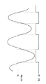
ところが、電源ライン間に存在する容量成分やインピーダンス成分の影響により発生する残留電圧の影響で、例えば図5のように仮停電後に誤ってゼロクロス信号が入力される場合があり、タイミングによっては、上述したバックアップ用の電源電池動作中に通常動作となり、電池の寿命が低下するような動作が発生することがある。 However, due to the influence of the residual voltage generated due to the influence of the capacitance component and impedance component existing between the power supply lines, for example, the zero cross signal may be erroneously input after the temporary power failure as shown in FIG. During the backup power supply battery operation, a normal operation may occur, and an operation may occur that reduces the battery life.
そこで、これに対する対処方法として、例えば(1)仮停電中は停電前の電源周期と異信号は無効として無視する、(2)IGBT駆動状態への復帰は複数回の正常なゼロクロス信号の入力により行うなどの措置を採用する。 Therefore, as countermeasures against this, for example, (1) During the temporary power failure, the power cycle before the power failure and the different signal are ignored and ignored. (2) The return to the IGBT driving state is performed by inputting a plurality of normal zero cross signals. Adopt measures such as taking action.
このようにすると、上述のような誤検出が無くなり、誤動作によるバックアップ用電源電池の寿命を低下させる弊害がなくなる。 This eliminates the above-described erroneous detection and eliminates the adverse effect of reducing the life of the backup power supply battery due to malfunction.
1は外ケース、2は蓋ユニット、3は内鍋、4は内ケース、6Aは制御基板、6Bはマイコン基板、24はノイズカット用コンデンサ、29Bは電圧検知回路、29cはゼロクロス検知回路、30はAC電源、32はマイコン制御ユニット、35は整流回路、H1は保温ヒータ、H2は肩ヒータ、Cはワークコイル、PCはフォトカプラ、Qはスイッチングトランジスタ、ZDは定電圧ダイオードである。 1 is an outer case, 2 is a lid unit, 3 is an inner pot, 4 is an inner case, 6A is a control board, 6B is a microcomputer board, 24 is a noise cut capacitor, 29B is a voltage detection circuit, 29c is a zero cross detection circuit, 30 Is an AC power source, 32 is a microcomputer control unit, 35 is a rectifier circuit, H 1 is a heat retaining heater, H 2 is a shoulder heater, C is a work coil, PC is a photocoupler, Q is a switching transistor, and ZD is a constant voltage diode.
Claims (5)
Priority Applications (1)
| Application Number | Priority Date | Filing Date | Title |
|---|---|---|---|
| JP2004120115A JP2005296491A (en) | 2004-04-15 | 2004-04-15 | Electric rice cooker |
Applications Claiming Priority (1)
| Application Number | Priority Date | Filing Date | Title |
|---|---|---|---|
| JP2004120115A JP2005296491A (en) | 2004-04-15 | 2004-04-15 | Electric rice cooker |
Publications (1)
| Publication Number | Publication Date |
|---|---|
| JP2005296491A true JP2005296491A (en) | 2005-10-27 |
Family
ID=35328739
Family Applications (1)
| Application Number | Title | Priority Date | Filing Date |
|---|---|---|---|
| JP2004120115A Pending JP2005296491A (en) | 2004-04-15 | 2004-04-15 | Electric rice cooker |
Country Status (1)
| Country | Link |
|---|---|
| JP (1) | JP2005296491A (en) |
Cited By (5)
| Publication number | Priority date | Publication date | Assignee | Title |
|---|---|---|---|---|
| JP2007289304A (en) * | 2006-04-24 | 2007-11-08 | Matsushita Electric Ind Co Ltd | rice cooker |
| JP2009041918A (en) * | 2007-08-06 | 2009-02-26 | Toto Ltd | Electronic instrument and toilet apparatus |
| JP2012249718A (en) * | 2011-05-31 | 2012-12-20 | Tiger Vacuum Bottle Co Ltd | Electric rice cooker |
| CN111012192A (en) * | 2019-12-31 | 2020-04-17 | 深圳市饭立得科技有限公司 | Drive control method of cooker |
| JP7674715B2 (en) | 2022-12-16 | 2025-05-12 | Anp株式会社 | Bidirectional power grid interconnection device |
-
2004
- 2004-04-15 JP JP2004120115A patent/JP2005296491A/en active Pending
Cited By (5)
| Publication number | Priority date | Publication date | Assignee | Title |
|---|---|---|---|---|
| JP2007289304A (en) * | 2006-04-24 | 2007-11-08 | Matsushita Electric Ind Co Ltd | rice cooker |
| JP2009041918A (en) * | 2007-08-06 | 2009-02-26 | Toto Ltd | Electronic instrument and toilet apparatus |
| JP2012249718A (en) * | 2011-05-31 | 2012-12-20 | Tiger Vacuum Bottle Co Ltd | Electric rice cooker |
| CN111012192A (en) * | 2019-12-31 | 2020-04-17 | 深圳市饭立得科技有限公司 | Drive control method of cooker |
| JP7674715B2 (en) | 2022-12-16 | 2025-05-12 | Anp株式会社 | Bidirectional power grid interconnection device |
Similar Documents
| Publication | Publication Date | Title |
|---|---|---|
| US6427581B1 (en) | Waffle maker with cooking temperature control | |
| JP2005296491A (en) | Electric rice cooker | |
| JP3891155B2 (en) | Electric rice cooker | |
| JP2004201804A (en) | Electric rice cooker | |
| JP3627714B2 (en) | Electric rice cooker | |
| JP3941793B2 (en) | Electric rice cooker | |
| JP3952038B2 (en) | Electric rice cooker | |
| JP2003325331A (en) | Induction heating electric rice cooker | |
| JP3187320B2 (en) | Electric rice cooker | |
| JP4821517B2 (en) | Electric rice cooker | |
| KR102355705B1 (en) | Heater assembly for electric cooker | |
| JP4041053B2 (en) | rice cooker | |
| JP2012235813A (en) | Electrical heater | |
| JP2920191B2 (en) | Electromagnetic rice cooker | |
| JP2639329B2 (en) | Electromagnetic rice cooker | |
| JP2005050725A (en) | Induction heating cooker | |
| JP2004113295A (en) | Electric cooker | |
| JPH074317B2 (en) | rice cooker | |
| JP2010088648A (en) | Rice cooker | |
| JP3906828B2 (en) | Electric rice cooker | |
| JP5652294B2 (en) | Heating toilet seat device | |
| KR0152410B1 (en) | Insulation control method of electric rice cooker | |
| JP2011224237A (en) | Electric rice cooker | |
| JPH0584127A (en) | Rice cooker | |
| JP6847004B2 (en) | rice cooker |
Legal Events
| Date | Code | Title | Description |
|---|---|---|---|
| A977 | Report on retrieval |
Effective date: 20061219 Free format text: JAPANESE INTERMEDIATE CODE: A971007 |
|
| A131 | Notification of reasons for refusal |
Free format text: JAPANESE INTERMEDIATE CODE: A131 Effective date: 20061226 |
|
| A02 | Decision of refusal |
Free format text: JAPANESE INTERMEDIATE CODE: A02 Effective date: 20070515 |