JP2005296478A - Information presentation system and 3-d marker - Google Patents
Information presentation system and 3-d marker Download PDFInfo
- Publication number
- JP2005296478A JP2005296478A JP2004119826A JP2004119826A JP2005296478A JP 2005296478 A JP2005296478 A JP 2005296478A JP 2004119826 A JP2004119826 A JP 2004119826A JP 2004119826 A JP2004119826 A JP 2004119826A JP 2005296478 A JP2005296478 A JP 2005296478A
- Authority
- JP
- Japan
- Prior art keywords
- marker
- information
- unit
- dimensional
- presentation system
- Prior art date
- Legal status (The legal status is an assumption and is not a legal conclusion. Google has not performed a legal analysis and makes no representation as to the accuracy of the status listed.)
- Pending
Links
- 239000003550 marker Substances 0.000 title claims abstract description 304
- 238000003384 imaging method Methods 0.000 claims description 12
- 238000005286 illumination Methods 0.000 claims description 8
- 230000001133 acceleration Effects 0.000 claims description 3
- 238000000034 method Methods 0.000 description 26
- 238000012545 processing Methods 0.000 description 21
- 230000008569 process Effects 0.000 description 19
- 230000010365 information processing Effects 0.000 description 18
- 238000002347 injection Methods 0.000 description 18
- 239000007924 injection Substances 0.000 description 18
- 230000000694 effects Effects 0.000 description 13
- 238000004458 analytical method Methods 0.000 description 9
- 238000003860 storage Methods 0.000 description 9
- 230000008859 change Effects 0.000 description 7
- 238000010276 construction Methods 0.000 description 7
- 230000009471 action Effects 0.000 description 5
- 238000010586 diagram Methods 0.000 description 5
- 238000005192 partition Methods 0.000 description 5
- 239000007787 solid Substances 0.000 description 5
- 238000004364 calculation method Methods 0.000 description 3
- 238000011161 development Methods 0.000 description 3
- 238000004891 communication Methods 0.000 description 2
- 238000009826 distribution Methods 0.000 description 2
- 239000000284 extract Substances 0.000 description 2
- 238000004519 manufacturing process Methods 0.000 description 2
- 230000004048 modification Effects 0.000 description 2
- 238000012986 modification Methods 0.000 description 2
- 238000003825 pressing Methods 0.000 description 2
- 125000002066 L-histidyl group Chemical group [H]N1C([H])=NC(C([H])([H])[C@](C(=O)[*])([H])N([H])[H])=C1[H] 0.000 description 1
- 238000005452 bending Methods 0.000 description 1
- 230000004397 blinking Effects 0.000 description 1
- 230000007123 defense Effects 0.000 description 1
- 238000013461 design Methods 0.000 description 1
- 230000008451 emotion Effects 0.000 description 1
- 239000012530 fluid Substances 0.000 description 1
- 230000005484 gravity Effects 0.000 description 1
- 239000004973 liquid crystal related substance Substances 0.000 description 1
- 230000003287 optical effect Effects 0.000 description 1
- 238000007781 pre-processing Methods 0.000 description 1
- 230000003252 repetitive effect Effects 0.000 description 1
- 230000009466 transformation Effects 0.000 description 1
- 238000000844 transformation Methods 0.000 description 1
Images


Abstract
Description
本発明は、情報呈示システム及び立体マーカに関するものである。 The present invention relates to an information presentation system and a three-dimensional marker.
従来より、遊戯カードとビデオゲームを組み合わせたゲームシステムが知られており、例えば、特開2001-334012号公報には、二次元コード等が印刷された遊戯カードに記憶された情報を読み出し、遊戯カードに記述されたキャラクタの個性を表現するデータ (音声または特徴情報等) を表示画面上に出力する情報呈示システムが記載されている。
しかしながら、前記した特開2001-334012号公報を含む従来の情報呈示システムは、カードが個性表現情報の入力手段として利用されているに過ぎず、操作者の裁量範囲はどのカードを選択するかに限られてしまい、多様性、遊戯性の点で満足いくものではなかった。 However, in the conventional information presentation system including the above-mentioned Japanese Patent Laid-Open No. 2001-334012, the card is merely used as an input means for personality expression information, and the discretion range of the operator is to select which card. It was limited and was not satisfactory in terms of diversity and playability.
本発明は、このような課題に着目してなされたものであり、その目的とするところは、多様性及び遊戯性に富んだ情報呈示システム及び立体マーカを提供することにある。 The present invention has been made paying attention to such problems, and an object of the present invention is to provide an information presentation system and a three-dimensional marker rich in diversity and playability.
前記の目的を達成するために、第1の発明は、複数の面を有し、該複数の面の少なくとも1つの面が平面で構成され、該平面には平面マーカが設けられる立体マーカを撮影して画像を取得する撮影手段と、前記立体マーカの平面に設けられた平面マーカを同定するマーカ同定部と、前記マーカ同定部からの同定情報に基づいて、前記平面マーカに関連する関連情報を呈示する情報呈示部とを具備する。 To achieve the above object, the first invention photographs a three-dimensional marker having a plurality of surfaces, at least one of the plurality of surfaces being a flat surface, and a flat marker provided on the flat surface. Imaging means for acquiring an image, a marker identifying unit for identifying a planar marker provided on the plane of the three-dimensional marker, and related information related to the planar marker based on identification information from the marker identifying unit And an information presentation unit to be presented.
また、第2の発明は、複数の面を有し、該複数の面の少なくとも1つの面が平面で構成され、該平面には平面マーカが設けられる立体マーカを撮影して画像を取得する撮影手段と、前記撮影により取得した画像を用いて、前記立体マーカの姿勢を判定する姿勢判定部と、前記立体マーカの平面に設けられた平面マーカを同定するマーカ同定部と、前記マーカ同定部からの同定情報と、前記姿勢判定部からの姿勢情報とに基づいて、前記平面マーカに関連する関連情報を呈示する情報呈示部とを具備する。 The second invention has a plurality of surfaces, and at least one of the plurality of surfaces is a plane, and a plane marker provided on the plane is photographed to obtain an image. Means, a posture determining unit that determines the posture of the three-dimensional marker using an image acquired by the photographing, a marker identifying unit that identifies a planar marker provided on a plane of the three-dimensional marker, and the marker identifying unit And an information presenting unit that presents related information related to the planar marker based on the identification information and the posture information from the posture determination unit.
また、第3の発明は、第2の発明に係る情報呈示システムにおいて、前記姿勢判定部は、基準面に配置したマーカ、前記撮影手段に設けられた加速度センサ、前記撮影手段に設けられたジャイロセンサ、前記撮影手段に設けられた磁気センサのうち少なくとも1つを含む。 According to a third aspect of the present invention, in the information presentation system according to the second aspect, the posture determination unit includes a marker disposed on a reference plane, an acceleration sensor provided in the photographing unit, and a gyro provided in the photographing unit. It includes at least one of a sensor and a magnetic sensor provided in the photographing means.
また、第4の発明は、第2の発明に係る情報呈示システムにおいて、前記撮影手段の撮影範囲の可動性は制限されており、前記姿勢判定部は、該制限により決まる可動領域に関する情報を用いて姿勢判定を行う。 According to a fourth aspect of the present invention, in the information presentation system according to the second aspect of the present invention, the mobility of the photographing range of the photographing means is limited, and the posture determination unit uses information on a movable region determined by the restriction. To determine posture.
また、第5の発明は、第1または第2の発明に係る情報呈示システムにおいて、前記情報呈示部は、前記撮影手段から取得した画像における前記立体マーカの位置及び/または姿勢に応じて異なる情報を呈示することを特徴とする請求項1または2記載の情報呈示システム。
According to a fifth aspect of the present invention, in the information presentation system according to the first or second aspect, the information presentation unit is different information depending on the position and / or orientation of the three-dimensional marker in the image acquired from the photographing unit. The information presentation system according to
また、第6の発明は、第1または第2の発明に係る情報呈示システムにおいて、前記立体マーカは複数であり、前記情報呈示部は、前記立体マーカ間の相対的な位置および/または姿勢に応じて異なる情報を呈示する。 According to a sixth aspect of the present invention, in the information presentation system according to the first or second aspect of the present invention, there are a plurality of the three-dimensional markers, and the information presenting unit has a relative position and / or posture between the three-dimensional markers. Present different information accordingly.
また、第7の発明は、第1または第2の発明に係る情報呈示システムにおいて、前記情報呈示部は、前記マーカ同定部により同定された平面マーカの組み合わせに応じて異なる情報を呈示する。 Moreover, 7th invention is an information presentation system which concerns on 1st or 2nd invention, The said information presentation part presents different information according to the combination of the plane marker identified by the said marker identification part.
また、第8の発明は、第1または第2の発明に係る情報呈示システムにおいて、前記立体マーカの各面に設けられる平面マーカはそれ自体の入れ替えおよび/または立体マーカに対する向きを入れ替え可能である。 In addition, according to an eighth aspect of the present invention, in the information presentation system according to the first or second aspect, the planar marker provided on each surface of the three-dimensional marker can replace itself and / or the direction relative to the three-dimensional marker. .
また、第9の発明は、第8の発明に係る情報呈示システムにおいて、前記入れ替え可能な平面マーカは台紙へ装着可能である。 According to a ninth aspect of the present invention, in the information presentation system according to the eighth aspect of the invention, the replaceable plane marker can be attached to the mount.
また、第10の発明は、第2の発明に係る情報呈示システムにおいて、前記立体マーカの構成情報を登録する構成登録部を有し、前記姿勢判定部は、前記構成登録部に登録された立体マーカの構成情報を用いて前記立体マーカの姿勢を判定する。 According to a tenth aspect of the present invention, in the information presentation system according to the second aspect of the present invention, the information registration system includes a configuration registration unit that registers the configuration information of the three-dimensional marker, and the posture determination unit is a three-dimensional registered in the configuration registration unit. The posture of the three-dimensional marker is determined using the marker configuration information.
また、第11の発明は、第10の発明に係る情報呈示システムにおいて、前記構成登録部は、前記立体マーカの構成情報をあらかじめ登録する。 According to an eleventh aspect of the present invention, in the information presentation system according to the tenth aspect, the configuration registration unit registers configuration information of the three-dimensional marker in advance.
また、第12の発明は、第10の発明に係る情報呈示システムにおいて、前記構成登録部は、前記撮影手段により取得した画像に基づいて前記立体マーカの構成情報を構築する。 According to a twelfth aspect of the present invention, in the information presentation system according to the tenth aspect of the invention, the configuration registration unit constructs the configuration information of the three-dimensional marker based on the image acquired by the photographing unit.
また、第13の発明は、第1または第2の発明に係る情報呈示システムにおいて、前記立体マーカは、穴を有する。 According to a thirteenth aspect of the present invention, in the information presentation system according to the first or second aspect, the three-dimensional marker has a hole.
また、第14の発明は、第1または第2の発明に係る情報呈示システムにおいて、前記平面マーカは電子的に表記が書き換え可能である。 According to a fourteenth aspect of the present invention, in the information presentation system according to the first or second aspect, the notation of the planar marker can be rewritten electronically.
また、第15の発明は、第1または第2の発明に係る情報呈示システムにおいて、前記撮影手段と前記立体マーカとの位置関係に応じて位置及び照度が可変である照明手段を有する。 According to a fifteenth aspect of the present invention, in the information presentation system according to the first or second aspect of the present invention, the information presentation system includes an illuminating unit whose position and illuminance are variable in accordance with a positional relationship between the photographing unit and the three-dimensional marker.
また、第16の発明は、第1または第2の発明に係る情報呈示システムにおいて、前記マーカ同定部において同定された前記平面マーカに応じて位置及び照度あるいは照明の色が変化する照明手段を有する。 According to a sixteenth aspect of the present invention, in the information presentation system according to the first or second aspect of the invention, there is provided an illuminating means whose position, illuminance, or illumination color changes according to the planar marker identified by the marker identifying unit. .
また、第17の発明は、第1または第2の発明に係る情報呈示システムにおいて、前記平面マーカに関連する関連情報は、前記撮影手段により取得された画像とは異なる画像上に重畳呈示される。 According to a seventeenth aspect of the present invention, in the information presentation system according to the first or second aspect, the related information related to the planar marker is superimposed and presented on an image different from the image acquired by the photographing means. .
また、第18の発明は、複数の面を有し、該複数の面の少なくとも1つの面が平面で構成され、該平面には平面マーカが設けられる立体マーカであって、前記立体マーカを撮影して画像を取得する撮影手段と、前記立体マーカの平面に設けられた平面マーカを同定するマーカ同定部と、前記マーカ同定部からの同定情報に基づいて、前記平面マーカに関連する関連情報を呈示する情報呈示部とを具備する。 According to an eighteenth aspect of the present invention, there is provided a three-dimensional marker having a plurality of surfaces, wherein at least one of the plurality of surfaces is a flat surface, and a flat marker is provided on the flat surface. Imaging means for acquiring an image, a marker identifying unit for identifying a planar marker provided on the plane of the three-dimensional marker, and related information related to the planar marker based on identification information from the marker identifying unit And an information presentation unit to be presented.
本発明によれば、多様性及び遊戯性に富んだ情報呈示システム及び立体マーカが提供される。 According to the present invention, an information presentation system and a three-dimensional marker rich in diversity and playability are provided.
以下、図面を参照して本発明の実施形態を詳細に説明する。 Hereinafter, embodiments of the present invention will be described in detail with reference to the drawings.
(第1実施形態)
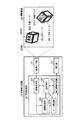
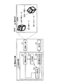
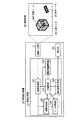
図1は、本発明の第1実施形態に係る情報呈示システムの構成を示す図である。本実施形態に係る情報呈示システムは、情報呈示装置10と立体マーカ(図では例として2つの立体マーカ20,20−1が図示されている)とから構成される。情報呈示装置10は、カメラ等の画像入力部11と、該画像入力部11で入力された画像を処理する情報処理部12と、該情報処理部12での処理結果として得られた情報を表示するディスプレイ等の表示部13とから構成されている。なお、前記画像入力部11は、所定の撮影範囲50を有する撮影手段として機能するものである。また、前記情報処理部12は、例えばゲーム機やパーソナルコンピュータ等の形態で提供されるもので、画像処理部121と、表示画像生成部122と、主制御部123と、マーカ同定部124と、姿勢判定部125とを含んでいる。表示画像生成部122と表示部13とは、マーカ同定部124からの同定情報と、姿勢判定部125からの姿勢情報とに基づいて、平面マーカに関連する関連情報を呈示する情報呈示部を構成する。
(First embodiment)
FIG. 1 is a diagram showing a configuration of an information presentation system according to the first embodiment of the present invention. The information presentation system according to the present embodiment includes an information presentation device 10 and a three-dimensional marker (two three-
前記画像入力部11としてのカメラ111は、図2に示すように、撮影範囲50の上方に設置してあり、その移動可能な範囲が可動領域150に制限されている。移動可能な範囲として表現される量は、画像入力部11の物理的な位置姿勢のみならず、ズームによる撮影範囲の変化量も含む。
As shown in FIG. 2, the camera 111 as the
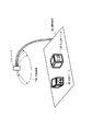
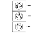
立体マーカ20,20−1を例とする立体マーカは、複数の平面から構成される立体形状であり、各平面には平面マーカ(例えば平面マーカ200,200−1)が貼付されている。立体マーカは、立方体や正十二面体のほかに、図3に示すような四角錐台201や、平板を曲げた形状202等の形態で提供される場合がある。また、立体マーカ20には、ストラップ等を取り付け可能な穴151が設けられている。
The three-dimensional marker taking the three-
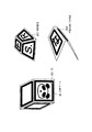
平面マーカは、例えばカードや板状のプラスチック等の形態で提供されるものであり、立体マーカに対して取り外し可能となっている。例えば、テープ等により貼り替え可能であってもよいし、図4に示すように立体マーカ20に設けたスリット204に平面マーカ200を差し込む形態であってもよい。また、平面マーカ200は、立体マーカ20に対して方向自在に取り付け可能な形態であってもよいことは勿論である。
The planar marker is provided in the form of, for example, a card or a plate-like plastic, and is removable from the three-dimensional marker. For example, it may be possible to replace with a tape or the like, or a form in which the
また、図4に示すように、平面マーカ200を立体マーカ20に取り付けないときに、該平面マーカ200を取り付けておくための台紙203も提供されている。該台紙203は、例えばクレジットカードサイズであって、取り付ける平面マーカ200に関する情報804が記載されていてもよい。
Further, as shown in FIG. 4, a mount 203 for attaching the
さらに、立体マーカの一面或いは複数面が液晶等の電子的ディスプレイである平面マーカで構成され、外部からの通信、または立体マーカに内蔵されたスイッチ等により任意の意匠や色を変化させるものであっても良い。 In addition, one or more surfaces of the three-dimensional marker are composed of a planar marker that is an electronic display such as a liquid crystal, and can change an arbitrary design or color by communication from the outside or a switch built in the three-dimensional marker. May be.
また、平面マーカは、少なくとも立体マーカに取り付けた状態において前記画像入力部11で撮影可能であるとともに、互いの相対的配置が既知である少なくとも3つ以上の特徴部位 (マーカの特徴点) を有し、可視情報が記述された媒体となっている。なお、本明細書において、「特徴部位」とは、撮影可能であり、画像から位置の特定が可能な部位のことであり、特徴領域、特徴点、特徴線分を含む。例えば、所定位置に記述された可視情報として図1に示すようなキャラクタ200Aが描かれ、そのキャラクタ200Aを囲む四角形の黒枠200Bを備えた平面マーカ200において、キャラクタ200Aと黒枠200Bをマーカとして利用するならば、黒枠200Bの四隅の頂点や黒枠200Bの線分を特徴部位とすることができる。
In addition, the planar marker can be photographed by the
前記情報処理部12の画像処理部121は、前記画像入力部11によって撮影された立体マーカ20の画像における前記3つ以上の特徴部位を特定し、その特定した特徴部位の前記画像入力部11に対する相対的位置姿勢を検出する。なお、特徴部位 (マーカの特徴点) の位置姿勢の算出の手法については、例えば、特開2000−227309号公報や特開2001−126051号公報に記載の方法を利用すれば良い。これにより、マーカの3つ以上の特徴点を特定することができれば、画像入力部11であるカメラ等と立体マーカ20との相対的位置姿勢を推定することができる。
The
また、上記情報処理部12のマーカ同定部124は、上記画像処理部121が検出した画像入力部11と立体マーカ20との相対的位置姿勢にもとづいて、立体マーカ20に貼付した平面マーカ200の中から処理対象とする平面マーカを特定する。
In addition, the
また、上記情報処理部12の姿勢判定部125は、上記画像処理部121が検出した画像入力部11と立体マーカ20との相対的位置姿勢にもとづいて、処理対象とする立体マーカ20の撮影範囲50で表現される実空間に対する位置姿勢を判定する。
In addition, the
また、上記情報処理部12の表示画像生成部122は、処理対象とする立体マーカ20の撮影範囲50で表現される実空間に対する位置姿勢およびマーカ同定部124で特定した処理対象とする平面マーカの情報から、該平面マーカに関連する関連情報を、前記画像入力部11によって撮影された画像に重ね合わせた表示画像(出力画像)を生成する。また、特に図1には図示していないが、前記関連情報に関するパラメータ(例えば、オブジェクト、コンテンツまたはモデルの状態を示す情報)を設定するパラメータ設定部、等を含む。例えば、該平面マーカにキャラクタが描かれている場合、関連情報としては、そのキャラクタの3Dモデルデータやそのキャラクタの喜怒哀楽や変身した姿などのバリエ−ションが考えられる。
In addition, the display
このように、平面マーカ上に描かれた可視情報の内容によって、関連情報としては各種のオブジェクトやコンテンツが考えられる。また、関連情報の呈示に伴い、平面マーカ上に描かれたキャラクタや前述の関連情報である3Dモデルに応じて図示しない照明の色や、照度、点滅、或いは照明位置を変化させることもゲーム等応用においては効果的演出に繋がることを確認している。 Thus, various objects and contents can be considered as related information depending on the contents of visible information drawn on the planar marker. In addition, with the presentation of related information, it is possible to change the illumination color (not shown), illuminance, blinking, or illumination position according to the character drawn on the planar marker or the 3D model that is the above-mentioned related information. In application, it has been confirmed that it leads to effective production.
更に照明については、立体マーカの位置や装置周辺の照明環境に応じて照度や照明位置、或いは複数照明の場合に各々の点灯状態を調整することも前述の「特徴部位」または処理対象とする平面マーカの情報から連結処理が可能であることは言うまでもない。 Furthermore, with respect to illumination, the above-mentioned “characteristic part” or a plane to be processed may be adjusted in accordance with the position of the three-dimensional marker and the illumination environment around the device, or the lighting state of each illumination in the case of multiple illuminations. Needless to say, the link processing can be performed from the marker information.
前記情報処理部12の主制御部123は、前記画像処理部121、表示画像生成部122、マーカ同定部124および姿勢判定部125を制御するものであり、また、特に図1には図示していないが、前記関連情報および立体マーカ20に貼付された平面マーカ200のID、テンプレート、位置姿勢等を記憶する記憶部を含む。
The
図5は、図1で説明した構成の変形例を示す図であり、図1の情報処理部12の構成要素から姿勢判定部125を除いたことを特徴とする。このような構成であっても、図1の構成と同等の効果が得られる。
FIG. 5 is a diagram showing a modified example of the configuration described in FIG. 1, and is characterized in that the
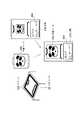
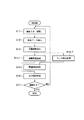
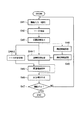
次に、図1に示す情報呈示装置10の動作を、図6のフローチャートを参照して説明する。まず、画像入力部11により立体マーカ20を含む画像を撮影する (ステップS11) 。例えば、立体マーカ20を所定の撮影範囲50に投げ込むことにより、図7(A)に示すような入力画像112が得られる。ここで、情報処理部12の主制御部123は、画像処理部121に、その入力画像112中から立体マーカ20に貼付した平面マーカ200を抽出させ (ステップS12) 、マーカ即ち立体マーカ20の画像入力部11に対する相対的な位置姿勢を検出させる (ステップS13) 。
Next, the operation of the information presentation apparatus 10 shown in FIG. 1 will be described with reference to the flowchart of FIG. First, an image including the three-
次に、主制御部123は、姿勢判定部125に、前記検出した相対的位置姿勢情報にもとづいて、立体マーカ20の撮影範囲50で表現される実空間に対する位置姿勢を判定させる(ステップS14−1)。この処理によって、撮影範囲50内に投入された立体マーカ20が操作者の存在する実空間に対して、どういった位置姿勢にあるのかが判定される。
Next, the
また、主制御部123は、マーカ同定部124に、上記検出した相対的位置姿勢情報にもとづいて、立体マーカ20に貼付した平面マーカのうち、処理対象とすべきものを特定させる (ステップS14−2) 。マーカ同定部124は、立体マーカ20に貼付した平面マーカで入力画像112から同定できたもののうち、入力画像内に占める面積が最大のものを立体マーカ20の上面、つまり処理対象となる平面マーカ200として特定する。
Further, the
その後、主制御部123は表示画像生成部122に、上記特定した平面マーカ200から、関連情報を特定するための情報であるテンプレートや関連付け情報 (マーカのID) を解析させる。そして、主制御部123は、その解析結果に対応する関連情報、例えばキャラクタの3Dモデルデータを、内部に備える不図示の記憶部から表示画像生成部122へ提供する(ステップS15)。
Thereafter, the
次に、主制御部123は表示画像生成部122に対し、上記関連情報の解析結果および姿勢判定結果にもとづいて、該表示画像生成部122の内部に備える不図示のパラメータ設定部により、その関連情報に関するパラメータ、例えばモデルの状態を示す情報を前記検出した相対的位置姿勢に基づいて変化させる関連情報解析処理を実行させ、該パラメータに従った上記関連情報、例えばキャラクタの3Dモデルを生成させ、実際に画像入力部11から得られた入力画像112にその3Dモデルを重畳した画面である出力情報を生成させる(ステップS16)。例えば、撮影範囲50を基準としたときの立体マーカ20の絶対的位置姿勢によって、立体マーカ20が撮影範囲50の概略位置手前に位置するときには、キャラクタの正面を画像入力部11の方向にするようパラメータを変更するが、撮影範囲50の奥に位置するときには、キャラクタの姿勢に関するパラメータを変更しないといった処理を実行する。なお、関連情報は、例えば通信により外部に設けられたサーバ等に問い合わせて得るようにしても良いことは勿論である。この生成された出力情報は、表示部13にて表示される。
Next, the
すなわち図7(B)に示すように、出力画像131は、立体マーカ20に貼付された処理対象となる平面マーカ200に対応するキャラクタの3Dモデル132が、立体マーカ20の絶対的位置姿勢に応じた状態で表示されることとなる。なお、出力情報としては、画像に限定されるものではなく、音声や振動等、操作者が関知できる刺激であっても良く、そのような出力情報とする場合には、音声出力部や振動出力部が情報呈示装置10に備えられることとなる。
That is, as illustrated in FIG. 7B, the output image 131 indicates that the 3D model 132 of the character corresponding to the
そしてその後、主制御部123は、処理を継続するか否かを判断する (ステップS17) 。この判断は、例えば操作者による終了指示の有無を判別することによって行うことができる。継続する場合には、前記ステップS11に戻る。
Thereafter, the
なお、主制御部123は、複数の立体マーカを投げ込み、マーカ同定部124が特定した平面マーカの組み合わせに応じて関連情報および/または関連情報に関するパラメータを変化させることも可能である。また、同様の処理は1つの立体マーカと1つの平面マーカ、複数の立体マーカと複数の平面マーカという組合せであっても可能であることは勿論である。
The
また、前記画像入力部11が複数の撮影装置から構成されていてもよい。この場合、一つは前記のように撮影範囲50の上方に設置し、それ以外は操作者の視線に近い位置に設置すると効果的な表示が可能となる。つまり、上方に設置した撮影装置から得られる画像にもとづいてステップS15までの処理がなされ、ステップS16の入力画像に3Dモデルを重畳した画面である出力情報を生成する段階で、操作者の視線に近い位置に設置した撮影装置から得られた画像を利用することにより、本システムは、臨場感の高い重畳画像を表示する。このためには、撮影範囲50の上方に設置した撮影装置とその他の撮影装置との相対的な位置姿勢が主制御部の不図示の記憶部に記憶されていればよい。
The
(第1実施形態の応用例)
前記のような第1実施形態の応用例としては、例えば、ゲームへの利用が考えられる。即ち、情報処理部12がゲーム機であり、該ゲーム機に画像入力部11としてのカメラが接続されている。カメラは立体マーカであるサイコロを出す場所周辺を撮影範囲とするよう設置してある。
(Application example of the first embodiment)
As an application example of the first embodiment as described above, for example, use in a game is conceivable. That is, the information processing unit 12 is a game machine, and a camera as the
サイコロには、入れ替え可能なカードが各面に取り付けられており、ストラップを取り付け可能な穴も設けられている。カードにはマーカとして機能するテンプレートが印刷されている。カードが入れ替え可能になっているので、操作者はサイコロに取り付けるカードを自由に選び、所望のカードの組合せからなるサイコロを実現できる。サイコロのように確率的に上面が決定される媒体で、かつ自由に取り付けるカードを選択できるため、ゲームとしての多様性が飛躍的に向上する。 The dice has a replaceable card attached to each side and a hole in which a strap can be attached. A template that functions as a marker is printed on the card. Since the cards can be exchanged, the operator can freely select a card to be attached to the dice and realize a dice composed of a desired combination of cards. Since the upper surface is stochastically determined like a dice and a card to be freely attached can be selected, the diversity as a game is dramatically improved.
撮影範囲50の上方に取り付けてあるカメラがサイコロを画像として捉えると、ゲーム機はサイコロの上面に取り付けられているカードを認識し、該カードに関連するキャラクタの3Dモデルを入力画像に重畳し出力する。この際、サイコロの位置、姿勢に応じて3Dモデルのパラメータを変化させる。サイコロが撮影範囲50の右側にあると「喜」の表情になり、下側にあると「怒」の表情になり、左側にあると「哀」の表情になり、上側にあると「楽」の表情になる。 When the camera attached above the shooting range 50 captures the dice as an image, the game machine recognizes the card attached to the upper surface of the dice, and superimposes and outputs the 3D model of the character related to the card on the input image. To do. At this time, the parameters of the 3D model are changed according to the position and orientation of the dice. If the dice is on the right side of the shooting range 50, it will look like "joy", if it is on the bottom, it will look like "angry", if it is on the left, it will look like "sorrow", and if it is on the top, it will be "easy". The expression becomes.
また、複数の操作者が各自のサイコロを投入し、対戦ゲームのモードも存在する。この場合には、複数のサイコロの相対的な位置姿勢によって、戦闘状態、待機状態を切り替える。 In addition, there is a battle game mode in which a plurality of operators throw their own dice. In this case, the battle state and the standby state are switched according to the relative positions and orientations of the plurality of dice.
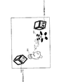
また、図8に示すように、操作者Aのサイコロ133に対応するキャラクタ250の正面が、操作者Bのサイコロ134に対応するキャラクタ251の側面を向いていた場合には、操作者Aの攻撃の効果は通常の150%となる。このように、複数のサイコロの相対的な位置のみならず、各組合せでの相対的な姿勢に応じてキャラクタの様々なパラメータを変更可能である。
Further, as shown in FIG. 8, when the front surface of the
また、同時もしくは順番に投入されたサイコロの上面の組合せによって、キャラクタの状態を変化させることも考えられる。例えば、キャラクタのカードを取り付けたサイコロと動作を意味するカードを取り付けたサイコロを同時に投入することで、登場させるキャラクタと、そのアクションを決定し、対応するアニメーションモデルを表示する。この場合、キャラクタについてはカードで呈示し、アクションについてのみサイコロとする、もしくはアクションについてはカードで呈示し、キャラクタについてのみサイコロとする、といった組合せであってもよい。 It is also conceivable to change the state of the character by combining the upper surfaces of the dice that are simultaneously or sequentially inserted. For example, by simultaneously inserting a dice to which a character's card is attached and a dice to which an action-meaning card is attached, a character to appear and its action are determined, and a corresponding animation model is displayed. In this case, the character may be presented as a card and the action may be a dice, or the action may be presented as a card and the character may be a dice.
(第2実施形態)
図9は、本発明の第2実施形態に係る情報呈示システムの構成を示す図である。第2実施形態における情報呈示装置10は、さらに構成情報構築部126を備えた情報処理部12により構成される。また、撮影範囲50の基準面、例えば床等に設置した基準マーカ21を構成要素として含む。
(Second Embodiment)
FIG. 9 is a diagram showing a configuration of an information presentation system according to the second embodiment of the present invention. The information presentation apparatus 10 in the second embodiment is further configured by the information processing unit 12 including a configuration
前記構成情報構築部126は、画像入力部11から得られる画像から平面マーカを同定し、立体マーカ20に対してどの平面マーカがどの位置にどの姿勢で取り付けられているかを示す構成情報を構築する。また、基準マーカ21は、平面マーカ200と同様の構成である。
The configuration
情報処理部12のマーカ同定部124は、上記画像処理部121が検出した画像入力部11と立体マーカ20および基準マーカ21との相対的位置姿勢にもとづいて、立体マーカ20に貼付した平面マーカ200の中から処理対象とする平面マーカを特定する。
The
情報処理部12の表示画像生成部122は、前記画像処理部121が検出した画像入力部11の立体マーカ20および基準マーカ21に対する相対的位置姿勢にもとづいて姿勢判定部125が判定した立体マーカ20の実空間に対する位置姿勢及びマーカ同定部124で特定した処理対象とする平面マーカ200の情報から、該平面マーカ200に関連する関連情報を、前記画像入力部11によって撮影された画像に重ね合わせた表示画像を生成するものである。例えば、該平面マーカ200にキャラクタが描かれている場合、関連情報としては、そのキャラクタの3Dモデルデータが考えられる。このように、平面マーカ200上に描かれた可視情報の内容によって、関連情報としては各種のオブジェクトやコンテンツが考えられる。
The display
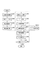
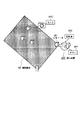
次に、前記した図9に示す構成の情報呈示装置10の動作を、図10のフローチャートを参照して説明する。まず、画像入力部11により、立体マーカ20の全面を撮影した画像列を取得する (ステップS21) 。ここで、構成情報構築部126は、前記画像列から立体マーカ20に貼付した平面マーカ200を抽出し (ステップS22) 、該平面マーカ200間の相対的な位置姿勢から、立体マーカ20に貼付されている平面マーカ200の構成情報を構築する (ステップS23) 。例えば、図11に示す画像列 (画像A,B,C) が得られることによって、該画像列が示す立体マーカ20の全面に貼付した平面マーカ200の構成情報が得られる。
Next, the operation of the information presentation apparatus 10 having the configuration shown in FIG. 9 will be described with reference to the flowchart of FIG. First, the
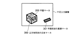
次に、前記構成情報を主制御部123へ送信すると、主制御部123は不図示の記憶部に記憶する (ステップS24) 。次に、画像入力部11は、立体マーカ20および基準マーカ21を含む画像を撮影する (ステップS25) 。例えば、立体マーカ20を基準マーカ21を含むよう設定した所定の撮影範囲50に投げ込むことにより、図12に示すような入力画像112が得られる。
Next, when the configuration information is transmitted to the
ここで、情報処理部12の主制御部123は、画像処理部121に、その入力画像112中から立体マーカ20に貼付した平面マーカ200および基準マーカ301を抽出させ (ステップS26) 、マーカ即ち立体マーカ20および基準マーカ21の画像入力部11に対する相対的な位置姿勢を検出させる (ステップS27) 。
Here, the
次に、主制御部123は、姿勢判定部125に、前記検出した相対的位置姿勢情報にもとづいて、立体マーカ20の撮影範囲50で表現される実空間に対する位置姿勢を判定させる(ステップS28−1)。この処理によって、撮影範囲50内に投入された立体マーカ20が操作者の存在する実空間に対して、どういった位置姿勢にあるのかが判定される。
Next, the
また、主制御部123は、マーカ同定部124に、前記検出した相対的位置姿勢情報にもとづいて、立体マーカ20に貼付した平面マーカ200のうち、処理対象とすべきものを特定させる (ステップS28−2) 。
Further, the
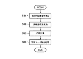
例えば、立体マーカ20が図12に示すような立方体300として構成されており、基準マーカ21が図12に示すような平面マーカ200として構成されており、基準マーカ21と同じ法線成分を持つ面を処理対象とすべき平面マーカとして特定する場合は、図13に示すステップで処理を実行する。なお、前記立方体300の構成情報はステップS21〜S24の処理によって、主制御部123の不図示の記憶部に記憶されている。
For example, the three-
ステップS31では、画像入力部11に対する立体マーカ20および基準マーカ21の相対的位置姿勢から、立体マーカ20に対する基準マーカ21の相対的位置姿勢を算出する。
In step S <b> 31, the relative position and orientation of the reference marker 21 with respect to the
ステップS32では、基準マーカ21の法線を立体マーカ20の座標系へと変換する。ステップS33では、ステップS32で変換した基準マーカ21の法線と、立方体300に貼付された各平面マーカの法線との内積を計算する。各平面マーカの法線は主制御部123の不図示の記憶部に記憶されている構成情報から取得する。
In step S <b> 32, the normal line of the reference marker 21 is converted into the coordinate system of the three-
ステップS34では、ステップS33で計算した内積が最大値となった平面マーカを特定する。 In step S34, the plane marker having the maximum inner product calculated in step S33 is specified.
その後、主制御部123は表示画像生成部122に、前記特定したマーカから、関連情報を特定するための情報であるテンプレートや関連付け情報 (マーカのID) を解析させる。そして、主制御部123は、その解析結果に対応する関連情報、例えばキャラクタの3Dモデルデータを内部に備える不図示の記憶部から表示画像生成部122へ提供する(ステップS29)。
Thereafter, the
次に、主制御部123は表示画像生成部122に対し、上記関連情報の解析結果および姿勢判定結果にもとづいて、該表示画像生成部122の内部に備える不図示のパラメータ設定部により、その関連情報に関するパラメータ、例えばモデルの状態を示す情報を前記検出した相対的位置姿勢に基づいて変化させる関連情報解析処理を実行させ、該パラメータに従った上記関連情報、例えばキャラクタの3Dモデルを生成させ、実際に画像入力部11から得られた入力画像112にその3Dモデルを重畳した画面である出力情報を生成させる (ステップS30) 。また、上記立方体300が3個以上存在する場合も、それぞれ最も近傍の立方体(立体マーカ)間の相対的位置姿勢にもとづいた変化を与えることも、また、3個またはそれ以上の相対的位置姿勢にもとづいた関連情報解析処理を進めることも可能である。この生成された出力情報は、表示部13にて表示される。
Next, the
このステップの変化系として、前記画像入力部11から得られた入力画像の代わりに、予めCG等で製作された画像や予め取得された背景画像を再生し、その上に3Dモデルを所定の位置姿勢で重畳し、表示部13にて出力する方法もある。この場合、背景画像のみを予め出力させ、実際に画像入力部11から得られた入力画像のうち、立体マーカ或いは平面マーカ部のみを切り出し、更に平面マーカの同定から指示される前記関連情報(3Dキャラクター等)を重畳表示すると言った3元重畳表示も応用可能である。
As a changing system of this step, instead of the input image obtained from the
これは、ゲーム等において立体マーカを投じる場を実際の造作物による脚色を図らずともCGデータ等の入れ替えのみにて簡単に異なるゲームに仕立て上げる事が出来る、と言ったコンテンツ製作上のコストメリットに繋がるし、ゲームのプレイヤーからも実写像とCG像との混在によるコンテンツ表現の幅の広さを教授できると言った効果がある。 This is a cost merit in content production that the place where a three-dimensional marker is thrown in a game etc. can be easily tailored to a different game just by replacing CG data etc. In addition, there is an effect that the player of the game can teach the wide range of content expression by mixing the real image and the CG image.
そしてその後、主制御部123は、継続するか否かを判断する (ステップS31) 。この判断は、例えば操作者による終了指示の有無を判別することによって行うことができる。継続する場合には、前記ステップS25に戻る。
Thereafter, the
このような構成、作用としても、前記第1実施形態と同様の効果が得られる。更にこの場合は、立体マーカの構成情報を取得するので、画像入力部11の可動範囲を撮影範囲50の上方に制限する必要がなくなり、1つのカメラであっても、重畳画像を操作者の視線に近いものにできるという効果もある。また画像入力部11を操作者が自由に動かすことも可能となる。画像入力部11の移動は操作者に限らず、第三者やシステムが機械的に行うことも可能であることは勿論である。
Even with this configuration and function, the same effects as those of the first embodiment can be obtained. Further, in this case, since the configuration information of the three-dimensional marker is acquired, there is no need to limit the movable range of the
なお、基準マーカ21は、立体マーカ20と同様の構成であってもよい。つまり、基準マーカ21も立体形状であり、各面に平面マーカ200と同等のものが貼付されていてもよい。この場合、基準マーカ21の所定の面を基準マーカの側面からも同定可能になるため、画像入力部11の撮影範囲50に対する位置姿勢の自由度が飛躍的に向上し、より多様な視点での重畳画像を提供する効果が得られる。
The reference marker 21 may have the same configuration as the three-
また、基準マーカ21に代わって、ジャイロセンサ、磁気センサ、加速度センサを利用してもよい。これらのセンサを利用した場合、カメラと撮影範囲50との3次元位置姿勢は一般に知られた方法で算出できるので、基準マーカ21の法線と同等の情報を持つ撮影範囲50の基準ベクトル、例えば重力方向を示すベクトル、を得られることになる。これにより、ステップS28における処理を、基準マーカ21を用いることなく実行することができる。 Further, instead of the reference marker 21, a gyro sensor, a magnetic sensor, or an acceleration sensor may be used. When these sensors are used, the three-dimensional position and orientation between the camera and the shooting range 50 can be calculated by a generally known method. Therefore, the reference vector of the shooting range 50 having information equivalent to the normal line of the reference marker 21, for example, A vector indicating the direction of gravity can be obtained. Thereby, the process in step S <b> 28 can be executed without using the reference marker 21.
なお、前記ステップS21で取得する立体マーカの全面の画像列は、画像入力部11を移動させることにより立体マーカの全周を撮影してもよいし、回転台上に立体マーカを設置し撮影してもよい。また、複数の撮影装置を用いてもよい。
Note that the image sequence of the entire surface of the stereoscopic marker acquired in step S21 may be captured by moving the
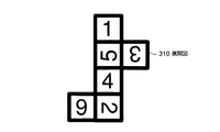
また、立体マーカを図14に示すような展開図310から組み立てる、もしくは展開図310を貼付する構成にした場合、該展開図310を撮影した少なくとも1枚の画像から構成情報を構築することが可能となり、ステップS21の工程を簡略化する効果が得られる。 Further, when the three-dimensional marker is assembled from the development drawing 310 as shown in FIG. 14 or the development drawing 310 is attached, the configuration information can be constructed from at least one image obtained by photographing the development drawing 310. Thus, the effect of simplifying the process of step S21 is obtained.
なお、図12の構成及び図13のフローチャートでは、基準マーカの法線が鉛直上方に一致しており、立体マーカの上面を処理対象の平面マーカとして特定すると仮定して述べたが、処理対象とする立体マーカの面は上面に限定されるものではなく、システムまたは操作者が規定した方向に最も近い面としたり、画像入力部11の光軸に最も近い面としてもよい。また、処理対象となる面は1面に限定されず、システムが規定する条件を満たす面全てとしてもよいことは勿論である。
In the configuration of FIG. 12 and the flowchart of FIG. 13, it has been described on the assumption that the normal line of the reference marker coincides vertically upward and the upper surface of the three-dimensional marker is specified as the planar marker to be processed. The surface of the three-dimensional marker to be performed is not limited to the upper surface, and may be the surface closest to the direction defined by the system or the operator or the surface closest to the optical axis of the
なお、構成情報は、操作者が画像入力とは異なる手段で指示してもよい。例えば、情報処理部がゲーム機として提供されている場合、ゲーム機のコントローラが画像入力とは異なる手段として利用できる。 Note that the configuration information may be instructed by the operator by means different from image input. For example, when the information processing unit is provided as a game machine, the controller of the game machine can be used as a means different from the image input.
(第3実施形態)
図15は、本発明の第3実施形態に係る情報呈示システムの構成を示す図である。本実施形態に係る情報呈示システムの構成および作用は第2実施形態と類似であるので、ここでは違いのみを述べる。
(Third embodiment)
FIG. 15 is a diagram showing a configuration of an information presentation system according to the third embodiment of the present invention. Since the configuration and operation of the information presentation system according to this embodiment are similar to those of the second embodiment, only the differences will be described here.
図16は、図15に示す情報呈示システムの作用を説明するためのフローチャートであり、ステップS41〜S47の処理は、第2実施形態のステップS25〜S31と同じである。 FIG. 16 is a flowchart for explaining the operation of the information presentation system shown in FIG. 15, and the processes in steps S41 to S47 are the same as steps S25 to S31 in the second embodiment.
情報処理部12の構成情報構築部126は、画像入力部11からではなく、画像処理部121から平面マーカ200の位置姿勢情報および平面マーカ200のIDを取得し、主制御部123から記憶している構成情報を取得する。主制御部123から取得した構成情報に不足している平面マーカ情報が画像処理部121から得られたときには、ステップS48の構成情報解析において該情報をマージする。そして、再度、主制御部123に記憶させる (ステップS49) 。
The configuration
このような構成、作用であっても、前記第1および第2実施形態と同様の効果が得られる。更にこの場合は、第2実施形態で行っていた事前の構成情報構築処理が省略され、繰り返し処理と並行に実行されるので、操作者はシステムを動作させるための繁雑な前処理から解放されるという効果が得られる。 Even if it is such a structure and an effect | action, the effect similar to the said 1st and 2nd embodiment is acquired. Further, in this case, the configuration information construction process performed in advance in the second embodiment is omitted, and the process is executed in parallel with the repetitive process, so that the operator is freed from complicated pre-processing for operating the system. The effect is obtained.
なお、本システムの画像入力部11は複数のカメラで構成されていてもよい。このときには、カメラ間の相対的な位置姿勢および認識した立体マーカ上の平面マーカの位置姿勢から構成情報を構築でき、1つのカメラの場合よりも、より確実性高く、少ない繰り返し回数で全ての構成情報を構築できる。
Note that the
(第4実施形態)
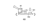
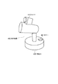
図17,図18は、本発明の第4実施形態に係る情報呈示システムについて説明するための図である。第4実施形態は、第2実施形態あるいは第3実施形態の構成において、立体マーカ20を射出する射出装置400を付加した構成である。該射出装置400は、撮影範囲50に対して立体マーカ20を射出する方向と強さを制御することができる。射出する強さは、射出装置400に接続もしくは取り付けられたボタン401を押す強さによって制御される。立体マーカ20は、射出装置400からバネ、空気圧等を利用した一般によく知られた方法で射出される。
(Fourth embodiment)
17 and 18 are diagrams for explaining an information presentation system according to the fourth embodiment of the present invention. The fourth embodiment is a configuration in which an
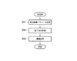
また、本システムは、射出装置400を利用した予想落下地点を表示する機能を有する。以下にこのような機能について図19、図20を参照して説明する。まず、主制御部123は、射出装置400のパラメータとしての方向および射出力を計測する (ステップSステップS51) 。例えば、射出装置400の回転軸にはエンコーダー等が取り付けられており、このエンコーダ出力から射出装置400の射出軸、つまり立体マーカ20の射出方向を計測することができる。また、前記のように射出力は、ボタン401を押す強さとして、ボタン401に取り付けた圧電素子等の出力から計測することができる。
In addition, this system has a function of displaying an expected drop point using the
次に、主制御部123が立体マーカ20の重量とステップS51で計測した射出装置400のパラメータから、立体マーカ20の落下地点を計算する (ステップS52) 。この計算は、いわゆる質点系の力学計算であってもよいし、体積や流体抵抗を考慮したものであってもよい。また、事前に各パラメータと落下地点との対応テーブルを構成しておき、該対応テーブルから落下地点をピックアップする方法であってもよいのは勿論である。
Next, the
また、落下地点は点としての位置情報ではなく、確率的に範囲を表現する形態であってもよい。例えば、確率60%で位置(x, y)を中心とする半径rの領域、確率90%で位置(x, y)を中心とする半径2rの領域という表現形態である。 Further, the falling point may not be positional information as a point, but may be a form in which the range is expressed stochastically. For example, the expression form is a region having a radius r centered on the position (x, y) with a probability of 60% and a region having a radius 2r centered on the position (x, y) with a probability of 90%.
この後、表示画像生成部122は、前記ステップS52で計算した予想落下地点の情報をCG化し、画像入力部11から得られる入力画像に重畳する (ステップS53) 。図20は、前記方法により重畳された予想落下地点408を示している。
Thereafter, the display
表示画像生成部122は、主制御部123を介して入手される画像入力部11と撮影範囲50との相対的位置姿勢情報にもとづいて、前記重畳処理を実行する。該相対的位置姿勢情報は、第2実施形態または第3実施形態で述べたように、画像入力部11と基準マーカ21との相対的位置姿勢情報として、画像入力部11より得られる入力画像から算出したものであってもよいが、図21に示すように射出装置400それ自身に画像入力部11としてのカメラ410を固着した構成であれば、射出装置400の射出方向情報にもとづいて算出することも可能である。
The display
このような構成、作用では、前記第2実施形態から第3実施形態に記述した効果に加え、操作者に対して予想落下地点408の重畳画像をインタラクティブに呈示できるので、より遊戯性の高いシステムを提供できるという効果を得る。 In such a configuration and operation, in addition to the effects described in the second to third embodiments, a superimposed image of the expected drop point 408 can be interactively presented to the operator, so that a system with higher playability The effect that can be provided.
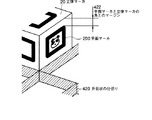
なお、前記構成に加えて、更に撮影範囲50に図22に示すような升目状の仕切り420を有するスタジアム(ゲームの場)421を設置してもよい。このような升目状の仕切り420を利用することにより、複数の立体マーカが過度に密集する状況を回避でき、画像処理部121における入力画像の解析時のエラーを減少させることが可能となる。
In addition to the above-described configuration, a stadium (game place) 421 having a grid-
また、升目状の仕切り420の高さを立体マーカ20に貼付する平面マーカ200と立体マーカ20自身の角とのマージン422(図23)以下にする場合、画像入力部11の可動領域を立体マーカ20の側方にまで拡大可能となり、より臨場感の高い重畳画像を提供可能となる。
When the height of the grid-
また、射出装置400に画像装置を取り付け、立体マーカ20が射出装置400に設置してあるときに、該立体マーカの構成情報を構築するための画像を撮影してもよい。立体マーカ20を射出する際の画像を利用してもよい。これらの画像を用いることにより、第3実施形態で示した構成情報の事前構築処理が実現される。
In addition, an image device may be attached to the
(第5実施形態)
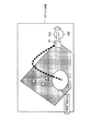
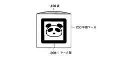
次に、本発明の第5実施形態を説明する。第5実施形態に係る情報呈示システムは、前記第1実施形態から第4実施形態の構成要素である平面マーカ200を図24に示すような袋450を有する袋状の構成へ変更したものである。すなわち、平面マーカ200は袋状になっており、その前面に画像処理部121での抽出対象となるマーカ部200−1が袋450よりも小さく貼り付けられている。袋450のマーカ部200−1が貼り付けられている面は、マーカ部200−1に覆われていない部分が透明もしくは半透明になっており、袋450の内部を観察可能な状態になっている。
(Fifth embodiment)
Next, a fifth embodiment of the present invention will be described. In the information presentation system according to the fifth embodiment, the
マーカ部200−1の形状情報および内部のテンプレートは主制御部123の不図示の記憶部に記憶されているが、関連情報は関連付けられていない。つまり、マーカ部200−1に対して、どの関連情報、例えばキャラクタの3Dモデルを関連付けるかは未定の状態である。
The shape information of the marker unit 200-1 and the internal template are stored in a storage unit (not shown) of the
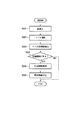
次に、第5実施形態における関連付けのステップを図25のフローチャートを用いて説明する。まず、操作者は所望の紙を平面マーカ200の袋450に挿入する (ステップS61) 。なお、紙でなくとも薄い平面状のもの等、袋450に挿入可能な形状・大きさであればよい。次に、画像入力部11は平面マーカ200を撮影し、袋450に挿入された紙を含む平面マーカ200の入力画像を取得する (ステップS62) 。ここで、画像処理部121は前記入力画像からマーカ部200−1の情報を抽出する (ステップS63)。
Next, association steps in the fifth embodiment will be described with reference to the flowchart of FIG. First, the operator inserts desired paper into the bag 450 of the flat marker 200 (step S61). In addition, the shape and size which can be inserted in the bag 450, such as a thin flat thing, may be sufficient even if it is not paper. Next, the
主制御部123は、前記マーカ部200−1のテンプレートに対応した関連情報の有無を判断する (ステップS64) 。関連情報が既に設定されている場合には、処理を終了する。一方、関連情報が設定されていない場合には、マーカ部200−1周辺8点の色情報を取得する (ステップS65) 。なお、上記のようにマーカ部200−1に覆われていない部分は、袋450内部を観察可能であるので、マーカ部200−1周辺8点の色情報は、袋450に挿入された紙により変化する。
The
主制御部123は前記色情報の平均値にもとづいて、関連付けする関連情報を決定する (ステップS66) 。例えば、平均色の色相値が0 (赤) であれば、炎のモンスターの3Dモデルを前記平面マーカ200−1に関連付ける。
The
このように平面マーカ200を構成することによって、操作者は自分自身の手によって関連情報、つまりキャラクタの3Dモデル、を決定することができ、より高い遊戯性を実現できる。
By configuring the
なお、ここでは、マーカ部200−1周辺8点の平均色を用いたが、関連付けを決定する情報源はこれに限定されるものではない。マーカ部200−1周辺の点数を変更してもよいし、線もしくは面状に情報を取得してもよい。また、このように取得する情報は色に限定されず、周波数成分、色分布、濃度分布等を用いてもよい。これらの複数の組み合わせも可能であることは勿論である。 Here, although the average color of 8 points around the marker unit 200-1 is used, the information source for determining the association is not limited to this. The number of points around the marker unit 200-1 may be changed, or information may be acquired in a line or a planar shape. Further, the information acquired in this way is not limited to color, and a frequency component, color distribution, density distribution, or the like may be used. Of course, a plurality of combinations of these are also possible.
また、マーカ部200−1周辺の情報から関連付ける関連情報を決定する方法は、予め組合せテーブルを作成しておいてもよいし、数式からパラメータとして決定してもよい。パラメータとして決定する場合、例えば、周辺の情報から、キャラクタの大きさをパラメータとして決定することが考えられる。また、キャラクタのHPや攻撃力、防御力といった属性情報をパラメータとして決定することも考えられる。 Moreover, the method of determining the relevant information linked | related from the information around marker part 200-1 may create the combination table previously, and may determine it as a parameter from numerical formula. When determining as a parameter, for example, it is conceivable to determine the character size as a parameter from surrounding information. It is also conceivable to determine attribute information such as the character's HP, attack power, and defense power as parameters.
また、平面マーカ200は必ずしも袋状である必要はなく、マーカ部200−1が貼付可能な形態になっていれば、所望の紙にマーカ部200−1を貼付することで平面マーカ200を構成してもよい。
Further, the
10…情報呈示装置、11…画像入力部、12…情報処理部、13…表示部、20、20−1…立体マーカ、50…撮影範囲、121…画像処理部、122…表示画像生成部、123…主制御部、124…マーカ同定部、125…姿勢判定部、200、200−1…平面マーカ。 DESCRIPTION OF SYMBOLS 10 ... Information presentation apparatus, 11 ... Image input part, 12 ... Information processing part, 13 ... Display part, 20, 20-1 ... Three-dimensional marker, 50 ... Shooting range, 121 ... Image processing part, 122 ... Display image generation part, 123: Main control unit, 124: Marker identification unit, 125: Posture determination unit, 200, 200-1: Planar marker.
Claims (18)
前記立体マーカの平面に設けられた平面マーカを同定するマーカ同定部と、
前記マーカ同定部からの同定情報に基づいて、前記平面マーカに関連する関連情報を呈示する情報呈示部と、
を具備することを特徴とする情報呈示システム。 An imaging unit that has a plurality of surfaces, at least one of the plurality of surfaces is configured by a plane, and images a stereoscopic marker provided with a plane marker on the plane;
A marker identifying unit for identifying a planar marker provided on the plane of the three-dimensional marker;
Based on the identification information from the marker identification unit, an information presenting unit that presents related information related to the planar marker;
An information presentation system comprising:
前記撮影により取得した画像を用いて、前記立体マーカの姿勢を判定する姿勢判定部と、
前記立体マーカの平面に設けられた平面マーカを同定するマーカ同定部と、
前記マーカ同定部からの同定情報と、前記姿勢判定部からの姿勢情報とに基づいて、前記平面マーカに関連する関連情報を呈示する情報呈示部と、
を具備することを特徴とする情報呈示システム。 An imaging unit that has a plurality of surfaces, at least one of the plurality of surfaces is configured by a plane, and images a stereoscopic marker provided with a plane marker on the plane;
A posture determination unit that determines a posture of the three-dimensional marker using an image acquired by the photographing;
A marker identifying unit for identifying a planar marker provided on the plane of the three-dimensional marker;
An information presentation unit for presenting related information related to the planar marker based on the identification information from the marker identification unit and the posture information from the posture determination unit;
An information presentation system comprising:
前記立体マーカを撮影して画像を取得する撮影手段と、
前記立体マーカの平面に設けられた平面マーカを同定するマーカ同定部と、
前記マーカ同定部からの同定情報に基づいて、前記平面マーカに関連する関連情報を呈示する情報呈示部と、
を具備する情報呈示システムにおいて用いられることを特徴とする立体マーカ。 A three-dimensional marker having a plurality of surfaces, wherein at least one surface of the plurality of surfaces is a plane, and the plane marker is provided on the plane;
Photographing means for photographing the stereoscopic marker to obtain an image;
A marker identifying unit for identifying a planar marker provided on the plane of the three-dimensional marker;
Based on the identification information from the marker identification unit, an information presenting unit that presents related information related to the planar marker;
A three-dimensional marker used in an information presentation system comprising:
Priority Applications (1)
| Application Number | Priority Date | Filing Date | Title |
|---|---|---|---|
| JP2004119826A JP2005296478A (en) | 2004-04-15 | 2004-04-15 | Information presentation system and 3-d marker |
Applications Claiming Priority (1)
| Application Number | Priority Date | Filing Date | Title |
|---|---|---|---|
| JP2004119826A JP2005296478A (en) | 2004-04-15 | 2004-04-15 | Information presentation system and 3-d marker |
Publications (1)
| Publication Number | Publication Date |
|---|---|
| JP2005296478A true JP2005296478A (en) | 2005-10-27 |
Family
ID=35328730
Family Applications (1)
| Application Number | Title | Priority Date | Filing Date |
|---|---|---|---|
| JP2004119826A Pending JP2005296478A (en) | 2004-04-15 | 2004-04-15 | Information presentation system and 3-d marker |
Country Status (1)
| Country | Link |
|---|---|
| JP (1) | JP2005296478A (en) |
Cited By (6)
| Publication number | Priority date | Publication date | Assignee | Title |
|---|---|---|---|---|
| WO2007108128A1 (en) * | 2006-03-23 | 2007-09-27 | Olympus Corporation | Information presenting apparatus and information presenting terminal |
| JP2011239996A (en) * | 2010-05-19 | 2011-12-01 | Bandai Co Ltd | Game machine |
| JP2018032111A (en) * | 2016-08-22 | 2018-03-01 | 株式会社ソニー・インタラクティブエンタテインメント | Information processing apparatus, information processing system, operation object, and information processing method |
| WO2023233583A1 (en) * | 2022-06-01 | 2023-12-07 | 株式会社ソニー・インタラクティブエンタテインメント | Electronic device, and information processing system |
| JP2025021633A (en) * | 2023-08-01 | 2025-02-14 | 株式会社コロプラ | Program and information processing system |
| JP7855066B2 (en) | 2022-06-01 | 2026-05-07 | 株式会社ソニー・インタラクティブエンタテインメント | Electronic equipment and information processing systems |
Citations (12)
| Publication number | Priority date | Publication date | Assignee | Title |
|---|---|---|---|---|
| JPS5931271Y2 (en) * | 1979-01-31 | 1984-09-05 | 暁教育図書株式会社 | letter dice |
| JPH0194879A (en) * | 1987-10-07 | 1989-04-13 | Taito Corp | Dice game machine |
| JPH05200156A (en) * | 1992-01-28 | 1993-08-10 | Sammy Ind Co Ltd | Dice game machine |
| JPH08266715A (en) * | 1995-03-31 | 1996-10-15 | Takeya Co Ltd | Pachinko machine |
| JPH11184620A (en) * | 1997-12-18 | 1999-07-09 | Fujitsu Ltd | Information processing device |
| JP2001300136A (en) * | 2000-04-25 | 2001-10-30 | Namco Ltd | Fortune-telling device and fortune-telling processing method |
| JP2002239207A (en) * | 2001-02-20 | 2002-08-27 | Omron Corp | Card game system, card game device, game card, and game method for card game |
| JP2002301264A (en) * | 2001-02-02 | 2002-10-15 | Sega Corp | Card game device, card data reading device, card game control method, recording medium, program, and card |
| JP2003103045A (en) * | 2001-09-28 | 2003-04-08 | Canon Inc | Video experience system and information processing method |
| JP2003135848A (en) * | 2001-10-31 | 2003-05-13 | Seiko Epson Corp | Contactless IC card, card game system, and card storage in card game system |
| JP2003230761A (en) * | 2002-02-07 | 2003-08-19 | Namco Ltd | Game board system, program and information storage medium |
| JP2003289552A (en) * | 2002-03-28 | 2003-10-10 | Toshiba Corp | Image display terminal device and stereoscopic image display system |
-
2004
- 2004-04-15 JP JP2004119826A patent/JP2005296478A/en active Pending
Patent Citations (12)
| Publication number | Priority date | Publication date | Assignee | Title |
|---|---|---|---|---|
| JPS5931271Y2 (en) * | 1979-01-31 | 1984-09-05 | 暁教育図書株式会社 | letter dice |
| JPH0194879A (en) * | 1987-10-07 | 1989-04-13 | Taito Corp | Dice game machine |
| JPH05200156A (en) * | 1992-01-28 | 1993-08-10 | Sammy Ind Co Ltd | Dice game machine |
| JPH08266715A (en) * | 1995-03-31 | 1996-10-15 | Takeya Co Ltd | Pachinko machine |
| JPH11184620A (en) * | 1997-12-18 | 1999-07-09 | Fujitsu Ltd | Information processing device |
| JP2001300136A (en) * | 2000-04-25 | 2001-10-30 | Namco Ltd | Fortune-telling device and fortune-telling processing method |
| JP2002301264A (en) * | 2001-02-02 | 2002-10-15 | Sega Corp | Card game device, card data reading device, card game control method, recording medium, program, and card |
| JP2002239207A (en) * | 2001-02-20 | 2002-08-27 | Omron Corp | Card game system, card game device, game card, and game method for card game |
| JP2003103045A (en) * | 2001-09-28 | 2003-04-08 | Canon Inc | Video experience system and information processing method |
| JP2003135848A (en) * | 2001-10-31 | 2003-05-13 | Seiko Epson Corp | Contactless IC card, card game system, and card storage in card game system |
| JP2003230761A (en) * | 2002-02-07 | 2003-08-19 | Namco Ltd | Game board system, program and information storage medium |
| JP2003289552A (en) * | 2002-03-28 | 2003-10-10 | Toshiba Corp | Image display terminal device and stereoscopic image display system |
Cited By (9)
| Publication number | Priority date | Publication date | Assignee | Title |
|---|---|---|---|---|
| WO2007108128A1 (en) * | 2006-03-23 | 2007-09-27 | Olympus Corporation | Information presenting apparatus and information presenting terminal |
| JP2011239996A (en) * | 2010-05-19 | 2011-12-01 | Bandai Co Ltd | Game machine |
| JP2018032111A (en) * | 2016-08-22 | 2018-03-01 | 株式会社ソニー・インタラクティブエンタテインメント | Information processing apparatus, information processing system, operation object, and information processing method |
| WO2018037975A1 (en) * | 2016-08-22 | 2018-03-01 | 株式会社ソニー・インタラクティブエンタテインメント | Information processing device, information processing system, operation object, and information processing method |
| US10957070B2 (en) | 2016-08-22 | 2021-03-23 | Sony Interactive Entertainment Inc. | Information processing apparatus, information processing system, operation object, and information processing method |
| WO2023233583A1 (en) * | 2022-06-01 | 2023-12-07 | 株式会社ソニー・インタラクティブエンタテインメント | Electronic device, and information processing system |
| JPWO2023233583A1 (en) * | 2022-06-01 | 2023-12-07 | ||
| JP7855066B2 (en) | 2022-06-01 | 2026-05-07 | 株式会社ソニー・インタラクティブエンタテインメント | Electronic equipment and information processing systems |
| JP2025021633A (en) * | 2023-08-01 | 2025-02-14 | 株式会社コロプラ | Program and information processing system |
Similar Documents
| Publication | Publication Date | Title |
|---|---|---|
| US9495800B2 (en) | Storage medium having stored thereon image processing program, image processing apparatus, image processing system, and image processing method | |
| JP5800484B2 (en) | Display control program, display control device, display control system, and display control method | |
| JP3686919B2 (en) | GAME DEVICE, GAME PROCESSING METHOD, AND READABLE STORAGE MEDIUM | |
| JP4757948B1 (en) | Information processing program, information processing apparatus, information processing system, and information processing method | |
| JP5541974B2 (en) | Image display program, apparatus, system and method | |
| JP5646263B2 (en) | Image processing program, image processing apparatus, image processing system, and image processing method | |
| JP5704962B2 (en) | Information processing system, information processing method, information processing apparatus, and information processing program | |
| JP5704963B2 (en) | Information processing system, information processing method, information processing apparatus, and information processing program | |
| US9662583B2 (en) | Portable type game device and method for controlling portable type game device | |
| JP5939733B2 (en) | Image processing program, image processing apparatus, image processing system, and image processing method | |
| JP5702653B2 (en) | Information processing program, information processing apparatus, information processing system, and information processing method | |
| JP5812628B2 (en) | Information processing program, information processing method, information processing apparatus, and information processing system | |
| JP5675260B2 (en) | Image processing program, image processing apparatus, image processing system, and image processing method | |
| JP5812665B2 (en) | Information processing system, information processing apparatus, information processing method, and information processing program | |
| JP5718603B2 (en) | Display control program, display control device, display control method, and display control system | |
| JP6039594B2 (en) | Information processing apparatus and information processing method | |
| JP2007042073A (en) | Video presentation system, video presentation method, program for causing computer to execute video presentation method, and storage medium | |
| JP2002233665A5 (en) | ||
| EP2565848B1 (en) | Program, information processing apparatus, information processing system, and information processing method | |
| JP5690135B2 (en) | Information processing program, information processing system, information processing apparatus, and information processing method | |
| JP5514637B2 (en) | Information processing program, information processing apparatus, information processing system, and information processing method | |
| JP2002247602A (en) | Image generator and control method therefor, and its computer program | |
| JP2011251006A (en) | Game program, portable game device, game system, and game method | |
| CN103002961B (en) | Game system and control method thereof | |
| JP2005296478A (en) | Information presentation system and 3-d marker |
Legal Events
| Date | Code | Title | Description |
|---|---|---|---|
| A621 | Written request for application examination |
Free format text: JAPANESE INTERMEDIATE CODE: A621 Effective date: 20060331 |
|
| A131 | Notification of reasons for refusal |
Free format text: JAPANESE INTERMEDIATE CODE: A131 Effective date: 20070206 |
|
| A02 | Decision of refusal |
Free format text: JAPANESE INTERMEDIATE CODE: A02 Effective date: 20070612 |