JP2005296443A - Traveling toy - Google Patents
Traveling toy Download PDFInfo
- Publication number
- JP2005296443A JP2005296443A JP2004119121A JP2004119121A JP2005296443A JP 2005296443 A JP2005296443 A JP 2005296443A JP 2004119121 A JP2004119121 A JP 2004119121A JP 2004119121 A JP2004119121 A JP 2004119121A JP 2005296443 A JP2005296443 A JP 2005296443A
- Authority
- JP
- Japan
- Prior art keywords
- foot
- rotation
- traveling toy
- shaft
- floor surface
- Prior art date
- Legal status (The legal status is an assumption and is not a legal conclusion. Google has not performed a legal analysis and makes no representation as to the accuracy of the status listed.)
- Abandoned
Links
Images
Landscapes
- Toys (AREA)
Abstract
【課題】動きの変化に富んだ走行玩具を提供することを目的とする。
【解決手段】床面等に設置される走行玩具であって、前記床面等に設置した状態で前記床面等に対して交差する方向に延在する回転軸と、前記回転軸を回転させる回転駆動装置と、前記床面等に設置された際に前記床面等に接地されると共に前記回転軸の回転によって前記回転軸の軸心を中心に回転する足部とを備え、前記回転軸及び前記足部の組が左右に設けられると共に、前記足部は、前記床面等を平面とした場合に、前記足部における前記床面等に接地する部分と前記回転軸の軸心との距離が前記回転軸の回転に伴って変化するように構成されていることを特徴とする
【選択図】図2An object of the present invention is to provide a traveling toy rich in changes in movement.
A traveling toy installed on a floor surface or the like, the rotating toy extending in a direction intersecting the floor surface or the like in a state of being installed on the floor surface or the like, and the rotation shaft being rotated A rotation drive device; and a foot that is grounded to the floor surface when installed on the floor surface and the like and rotates about the axis of the rotation shaft by the rotation of the rotation shaft. And the pair of feet is provided on the left and right, and when the floor is a flat surface, the foot is a portion of the foot that contacts the floor or the like and the axis of the rotation shaft. The distance is configured to change with the rotation of the rotating shaft.
Description
本発明は、走行玩具に関するものである。 The present invention relates to a traveling toy.
従来、床面等に設置される走行ロボットとして、前記床面等に設置した状態で前記床面等に対して交差する方向に延在する回転軸と、前記回転軸を回転させる回転駆動装置と、前記床面等に設置された際に前記床面等に接地されると共に前記回転軸の回転によって前記回転軸の軸心を中心に回転する足部とを備えるものが知られている。(たとえば特許文献1)
しかし、上記特許文献1の走行ロボットでは、足部は、床面等を平面とした場合に、足部における床面等に接地する部分と回転軸の軸心との距離が回転軸の回転に伴って変化しないので、動きの変化に乏しいという問題がある。 However, in the traveling robot disclosed in Patent Document 1, when the foot is a flat floor surface, the distance between the portion of the foot that is in contact with the floor or the like and the axis of the rotation shaft is the rotation of the rotation shaft. Since it does not change with it, there is a problem that the change of movement is scarce.
本発明は、かかる問題点に鑑みてなされたもので、動きの変化に富んだ走行玩具を提供することを目的とする。 The present invention has been made in view of such problems, and an object thereof is to provide a traveling toy rich in movement.
請求項1に記載の走行玩具は、床面等に設置される走行玩具であって、前記床面等に設置した状態で前記床面等に対して交差する方向に延在する回転軸と、前記回転軸を回転させる回転駆動装置と、床面等に設置された際に前記床面等に接地されると共に前記回転軸の回転によって前記回転軸の軸心を中心に回転する足部とを備え、前記回転軸及び前記足部の組が左右に設けられると共に、前記足部は、前記床面等を平面とした場合に、前記足部における前記床面等に接地する部分と前記回転軸の軸心との距離が前記回転軸の回転に伴って変化するように構成されていることを特徴とする。 The traveling toy according to claim 1 is a traveling toy installed on a floor surface or the like, and a rotating shaft extending in a direction intersecting the floor surface or the like in a state of being installed on the floor surface or the like, A rotation drive device that rotates the rotation shaft, and a foot that is grounded to the floor surface and the like when installed on the floor surface and rotates about the axis of the rotation shaft by rotation of the rotation shaft. A pair of the rotation shaft and the foot portion is provided on the left and right, and the foot portion is a portion of the foot portion that contacts the floor surface and the rotation shaft when the floor surface or the like is a plane. The distance from the center of the shaft is configured to change with the rotation of the rotating shaft.
請求項2に記載の走行玩具は、請求項1に記載の走行玩具において、前記回転軸に対して前記足部の初期回転角度を調整できるように構成されていることを特徴とする。 A traveling toy according to a second aspect is characterized in that, in the traveling toy according to the first aspect, an initial rotation angle of the foot portion can be adjusted with respect to the rotation axis.
請求項3に記載の走行玩具は、請求項1又は2に記載の走行玩具において、全体が動物を模した形状に構成され、前記足部が前記動物の足に対応していることを特徴とする。
The traveling toy according to
請求項4に記載の走行玩具は、請求項3に記載の走行玩具において、前記動物は四足歩行の動物であることを特徴とする。
The traveling toy according to claim 4 is the traveling toy according to
請求項1から4の発明によれば、床面等に対して交差する方向に延在する回転軸を回転させることによって、回転軸の軸心を中心に足部が回転して走行するので、意外性があり、興趣性の高い走行玩具が実現できる。また、足部は、床面等を平面とした場合に、足部における床面等に接地する部分と回転軸の軸心との距離が回転軸の回転に伴って変化するので、回転軸の回転に伴って走行玩具を上下方向や左右方向に揺動させることもできる。 According to the first to fourth aspects of the invention, by rotating the rotating shaft that extends in the direction intersecting the floor surface or the like, the foot rotates around the axis of the rotating shaft, and thus travels. A traveling toy that is surprising and highly interesting can be realized. In addition, when the floor is flat, the distance between the portion of the foot that is in contact with the floor or the like and the axis of the rotation shaft changes with the rotation of the rotation shaft. The traveling toy can be swung up and down or left and right with rotation.
請求項2に記載の走行玩具によれば、回転軸に対して足部の初期回転角度を調整できるので、左右の足部の初期回転角度を変えれば、様々な動きをさせることができる。
According to the traveling toy according to
請求項3及び4に記載の走行玩具によれば、床面等に対して交差する方向に延在する回転軸を回転させることによって、回転軸の軸心を中心に足部が回転し、これによって動物模型が走行するので、意外性があり、興趣性の高い走行玩具が実現できる。
According to the traveling toy according to
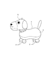
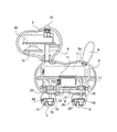
図1は、本発明に係る走行玩具の斜視図、図2は、その走行玩具を側面から見た場合の断面図である。 FIG. 1 is a perspective view of a traveling toy according to the present invention, and FIG. 2 is a cross-sectional view of the traveling toy as viewed from the side.
(全体構成)
この走行玩具1は全体が犬を模した形状に構成されている。この走行玩具1の足部2は球状体で構成されている。そして、この走行玩具1は、床面等に交差する方向に延在する軸心を中心として足部2がその場で偏心回転することで、走行玩具1が走行するように構成されている。
(overall structure)
The traveling toy 1 is configured in a shape imitating a dog as a whole. The
(細部構成)
図2に示すように、胴部3の前側部分にはスプリング4を介して頭部5が支持されている。胴部3にスプリング4を介して頭部5が支持されているため、胴部3が振動すると頭部5は小刻みに揺れることになる。この場合のスプリング4はリーフスプリングでもコイルスプリングであってもよい。一方、胴部3の後側部分には尾部6が付設されている。また、胴部3の下側には前後2つずつの足部2が付設されている。この足部2は球状体で構成されているが、その他の形状でもよい。特に限定はされないが、足部2の下側部分が面で接地しないように湾曲していることが好ましい。また、足部2は、床面等を平面とした場合に、足部2における床面等に接地する部分と後述の軸23,25の軸心との距離が回転軸の回転に伴って変化するように構成されている。
胴部3の内部には上側に電池7が設置されている。電池7は、胴部3の背部3aを取り外すことで交換ができるようになっている。また、胴部3の内部には下側にモータ8が設置されている。モータ8は横置きされ、モータ軸が本体から前方へ向けて突出するように設置されている。このモータ8は、胴部3及び足部2の内部に設けた駆動手段10を介して足部2に連結されている。
(Detailed configuration)
As shown in FIG. 2, a
A
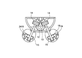
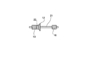
駆動手段10は歯車11,12,13,14,15,16,17,18及びキー19,20を含んで構成されている。このうち歯車11はモータ軸に付設されている。歯車12は,モータ軸と平行に延在する軸21に付設されており、歯車11に噛合している。歯車13(図4)はクラッチ22を介して歯車12に連結されている。すなわち、歯車12は軸21の前部に空転可能に取り付けられ、歯車13は軸21に固定されている。そして、歯車12と歯車13とはマグネットを介して連結され、常態では、歯車12及び歯車13はマグネットで連結されて一体的に回転するが、歯車12及び歯車13の間に過負荷が作用すると、歯車12及び歯車13の連結がマグネットの磁力に打ち勝って解除されるようになっている。歯車13はウォーム歯車である。歯車14は、走行玩具1が設置される床面等に対して交差する方向に延在する軸23(回転軸)に固定されている。この歯車14は歯車13に噛合している。歯車15は前側の足部2内にまで延びる軸23の下端部に固定されている。キー19は足部2内に設置され、スプリング24の付勢力によって歯車15に向けて付勢されている。そして、キー18はスプリング24の付勢力で歯車15の歯に噛合している。
図4に示すように、歯車16は軸21の後部に固定されている。この歯車16はウォーム歯車である。歯車17は、走行玩具1が設置される床面等に対して交差する方向に延在する軸(回転軸)25に固定されている。歯車18は前側の足部2内にまで延びる軸25の下端部に固定されている。キー20は足部2内に設置され、スプリング26の付勢力によって歯車18に向けて付勢されている。そして、キー20はスプリング26の付勢力で歯車18の歯に噛合している。
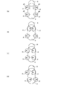
なお、図2では走行玩具1の左側の駆動手段10を説明したが、走行玩具1の右側にも同様の駆動手段10が左右対称に設けられている。ただし、モータ8、歯車11、及び軸21の付設要素は左右共通である。この場合、それぞれの足部2の回転方向は、特に制限はされないが、図5(A)に示す方向である。勿論、それに限定はされない。
また、図2において符号30はIC(半導体集積回路)チップが付設された基板を、符号31はスピーカを、符号32はスイッチを示し、スイッチ32を押圧することによってモータ8がON,OFFされるようになっていると共にスピーカ31から音が出力されるようになっている。
The driving means 10 includes
As shown in FIG. 4, the
In FIG. 2, the driving means 10 on the left side of the traveling toy 1 has been described. However, similar driving means 10 are provided symmetrically on the right side of the traveling toy 1. However, the attached elements of the
In FIG. 2,
(使用方法)
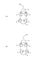
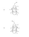
図5から図7は走行玩具1を下側から見た場合の概念図であり、足部2の初期の初期角度位置を示している。この初期角度位置は遊戯者が足部2を回転させることによって変えることができる。足部2を回転させる場合には、キー19,20がスプリング24,26の付勢力に抗して歯車15,18の歯から一旦外れることになる。
(how to use)
5 to 7 are conceptual diagrams when the traveling toy 1 is viewed from the lower side, and shows an initial initial angular position of the
図5(A)は第1モードの初期角度位置を示している。この初期角度位置が標準位置である。この位置では、4つの足部2の全てが軸23,25に対して横方向且つ外方に偏心している。この場合には、軸23,25の回転に伴う足部2における床面等に接地する部分と軸23,25の軸心との距離(動径)が左右前後で等しくなるので、左右及び前後の揺れが少ない。この場合には走行玩具1は前進する。
FIG. 5A shows the initial angular position in the first mode. This initial angular position is the standard position. In this position, all of the four
図5(B)は第2モードの初期角度位置を示している。この位置では、前側の足部2が軸23に対して横方向且つ内方に偏心する一方で、後側の足部2が軸25に対して横方向且つ外方に偏心している。この場合には、前側の足部2の動径の増減と、後側の足部2の動径の増減とが互いに逆となるので、縦揺れが生じることになる。この場合にも走行玩具1は前進する。
FIG. 5B shows the initial angular position in the second mode. In this position, the
図5(C)は第3モードの初期角度位置を示している。この位置では、4つの足部2の全てが軸23,25に対して(下側から見て)左方向に偏心している。この場合には、左側の足部2の動径の増減と、右側の足部2の動径の増減とが互いに逆となるので、横揺れが生じることになる。この場合にも走行玩具1は前進する。
FIG. 5C shows the initial angle position in the third mode. In this position, all of the four
図5(D)は第4モードの初期角度位置を示している。この位置では、前側の足部2が軸23に対して(下側から見て)左方向に偏心する一方で、後側の足部2が軸25に対して(下側から見て)右方向に偏心している。この場合には、激しく横揺れすることになる。この場合にも走行玩具1は前進する。
FIG. 5D shows the initial angular position in the fourth mode. In this position, the
図6(A),(B)は第5モード,第6モードの初期角度位置を示している。図6(A)の位置では、前側の足部2が軸23に対して前方向に偏心する一方で、後側の足部2が軸25に対して(下側から見て)左方向に偏心している。図6(B)の位置では、前側の足部2が軸23に対して前方に偏心する一方で、後側の足部2が軸25に対して(下側から見て)右方向に偏心している。これらの場合には、後側の足部2が偏心している方向に曲がることになる。
6A and 6B show initial angle positions in the fifth mode and the sixth mode. 6A, the
図7(A),(B)は第7モード,第8モードの初期角度位置を示している。図7(A)の位置では、前側の足部2が軸23に対して(下側から見て)左方向に偏心する一方で、後側の足部2が軸25に対して前方向に偏心している。図7(B)の位置では、前側の足部2が軸23に対して(下側から見て)右方向に偏心する一方で、後側の足部2が軸25に対して前方に偏心している。これらの場合には、前側の足部2が偏心している方向とは逆の方向に曲がることになる。
7A and 7B show the initial angular positions of the seventh mode and the eighth mode. 7A, the
(発明の変形)
以上、本発明について説明したが、本発明は、かかる実施形態に限定されるものではなく、その要旨を逸脱しない範囲で種々の変形が可能である。
(Modification of the invention)
As mentioned above, although this invention was demonstrated, this invention is not limited to this embodiment, A various deformation | transformation is possible in the range which does not deviate from the summary.
たとえば、着座用リングに走行玩具1を着座させて、たとえば尻部分が着座用リングに乗るように走行玩具1を着座させ、走行玩具1を着座させたままで後側の足部2の回転だけで着座用リング40の上で走行玩具1をその場回転させることもできる。 For example, the traveling toy 1 is seated on the seating ring, and the traveling toy 1 is seated so that, for example, the butt portion rides on the seating ring. The traveling toy 1 can also be rotated in place on the seating ring 40.
また、2足歩行の動物玩具にも適用できる。この場合、左右に足部2を設けて、その他の部分にキャスタや、あらゆる方向に移動自在となるようにボールを設けてもよい。さらに、自動車玩具やロボットの車輪の代わりに足部2を設けてもよい。
It can also be applied to bipedal animal toys. In this case, the
さらに、軸23,25の床面等との交差角度を変更できるようにしてもよい。
Furthermore, you may enable it to change the intersection angle with the floor surface etc. of the
また、歯車15,18、キー19,20及びスプリング24,26の代わりにワンウェイクラッチを設けて足部2と軸23,25の連結、連結解除をさせるようにしていもよい。
Further, a one-way clutch may be provided in place of the
さらに、上記実施形態の走行玩具1では、足部2の回転速度について触れなかったが、前後の足部2の間で回転速度をかえてもよい。また、足部2の回転方向も上記実施形態の走行玩具1に限定されるものではなく、前後又は左右で変更してもよい。この場合、適宜に足部2の回転方向を切り替えられるような構成としてもよい。
Furthermore, in the traveling toy 1 of the above embodiment, the rotational speed of the
1 走行玩具
2 足部
3 胴部
5 頭部
8 モータ
23,25 回転軸
1 traveling
Claims (4)
Priority Applications (1)
| Application Number | Priority Date | Filing Date | Title |
|---|---|---|---|
| JP2004119121A JP2005296443A (en) | 2004-04-14 | 2004-04-14 | Traveling toy |
Applications Claiming Priority (1)
| Application Number | Priority Date | Filing Date | Title |
|---|---|---|---|
| JP2004119121A JP2005296443A (en) | 2004-04-14 | 2004-04-14 | Traveling toy |
Publications (1)
| Publication Number | Publication Date |
|---|---|
| JP2005296443A true JP2005296443A (en) | 2005-10-27 |
Family
ID=35328697
Family Applications (1)
| Application Number | Title | Priority Date | Filing Date |
|---|---|---|---|
| JP2004119121A Abandoned JP2005296443A (en) | 2004-04-14 | 2004-04-14 | Traveling toy |
Country Status (1)
| Country | Link |
|---|---|
| JP (1) | JP2005296443A (en) |
-
2004
- 2004-04-14 JP JP2004119121A patent/JP2005296443A/en not_active Abandoned
Similar Documents
| Publication | Publication Date | Title |
|---|---|---|
| JPH0325826Y2 (en) | ||
| EP1251916B1 (en) | Remotely controlled skateboard having motion-responsive doll riding thereon | |
| US7258591B2 (en) | Mobile roly-poly-type apparatus and method | |
| US6398618B1 (en) | Motorized transmission for imparting motion to a display | |
| JP2002200368A (en) | Radio-controlled bicycle | |
| JPH11104362A (en) | Independent traveling toys | |
| US3940879A (en) | Walking doll | |
| JP2005296443A (en) | Traveling toy | |
| CN203196313U (en) | Music rocking toy car | |
| CN213131907U (en) | Deformable toy car capable of being controlled to unfold | |
| CN210356013U (en) | Remote control toy car | |
| JP3140175U (en) | Motor robot | |
| JP3111394U (en) | Battery car with an eccentric mechanism | |
| JPH11188186A (en) | Rolling toy | |
| JP4252357B2 (en) | Front wheel side suspension device for automobile toys | |
| JP2881673B2 (en) | Arm swing device for robot toys, etc. | |
| JPS642797Y2 (en) | ||
| JPH03233Y2 (en) | ||
| CN219983896U (en) | Improved crawling toy | |
| CN108686381A (en) | a climbing toy | |
| JP4981655B2 (en) | Motor robot | |
| JP4198457B2 (en) | A toy that rotates by moving the center of gravity within the toy body | |
| JP3136336U (en) | Anomalous traveling toy | |
| JPH0112858Y2 (en) | ||
| KR20010089835A (en) | A toy car in the shape of ball |
Legal Events
| Date | Code | Title | Description |
|---|---|---|---|
| A621 | Written request for application examination |
Free format text: JAPANESE INTERMEDIATE CODE: A621 Effective date: 20070301 |
|
| A762 | Written abandonment of application |
Free format text: JAPANESE INTERMEDIATE CODE: A762 Effective date: 20081209 |