JP2005296350A - Endoscope system - Google Patents
Endoscope system Download PDFInfo
- Publication number
- JP2005296350A JP2005296350A JP2004117108A JP2004117108A JP2005296350A JP 2005296350 A JP2005296350 A JP 2005296350A JP 2004117108 A JP2004117108 A JP 2004117108A JP 2004117108 A JP2004117108 A JP 2004117108A JP 2005296350 A JP2005296350 A JP 2005296350A
- Authority
- JP
- Japan
- Prior art keywords
- rigid
- sterilization bag
- endoscope
- peripheral surface
- imaging device
- Prior art date
- Legal status (The legal status is an assumption and is not a legal conclusion. Google has not performed a legal analysis and makes no representation as to the accuracy of the status listed.)
- Withdrawn
Links
Images


Landscapes
- Endoscopes (AREA)
Abstract
【課題】 硬性鏡を露出させつつ撮像装置を滅菌袋で覆う内視鏡システムを、提供する。
【解決手段】
硬性鏡10の接眼部13外周面には、複数のバイヨネット扇部13cが周方向に等角度間隔で突出形成されている。架台2に装着された撮像装置14の一側面には、接眼部13が挿入される開口である硬性鏡挿入部14aが穿たれている。また、この硬性鏡挿入部14aの縁には、この構成鏡挿入部14aに接眼部13が挿入された硬性鏡10の各バイヨネット扇部13cに係合するバイヨネットがその内周面に形成された円筒状のマウント口金22が突出形成されている。このマウント口金22の外周面には、円環状の外溝部22dが形成されている。滅菌袋アダプタ4は、マウント口金22の外周面に嵌る内周面形状を有する筒状部材であり、撮像装置14及び架台2を覆う滅菌袋3の先端に貫通した状態で、この滅菌袋3に対して液密且つ気密に接着されている。
【選択図】 図14PROBLEM TO BE SOLVED: To provide an endoscope system for covering an imaging device with a sterilization bag while exposing a rigid endoscope.
[Solution]
On the outer peripheral surface of the eyepiece 13 of the rigid endoscope 10, a plurality of bayonet fan portions 13c are formed protruding at equal angular intervals in the circumferential direction. A rigid endoscope insertion portion 14a that is an opening into which the eyepiece 13 is inserted is bored on one side surface of the imaging device 14 mounted on the gantry 2. In addition, a bayonet that engages with each bayonet fan portion 13c of the rigid endoscope 10 in which the eyepiece 13 is inserted into the constituent mirror insertion portion 14a is formed on the inner peripheral surface of the edge of the rigid endoscope insertion portion 14a. A cylindrical mount base 22 is formed so as to protrude. An annular outer groove 22 d is formed on the outer peripheral surface of the mount base 22. The sterilization bag adapter 4 is a cylindrical member having an inner peripheral surface shape that fits on the outer peripheral surface of the mount base 22. The sterilization bag adapter 4 is inserted into the sterilization bag 3 so as to penetrate the distal end of the sterilization bag 3 that covers the imaging device 14 and the gantry 2. On the other hand, it is liquid-tight and air-tight.
[Selection] FIG.
Description
本発明は、硬性鏡の基端に撮像装置を固定してなるビデオ式硬性鏡装置を滅菌袋で覆う内視鏡システムに関する。 The present invention relates to an endoscope system in which a video rigid endoscope apparatus in which an imaging apparatus is fixed to a proximal end of a rigid endoscope is covered with a sterilization bag.
例えば内臓や関節の患部の手術を体壁を切開することなく内視鏡観察下で行うために用いられる内視鏡装置の一つとして、体壁に開けられた小さな孔を通して患者の体内に挿入される硬性鏡と、この硬性鏡によって得られる患部の像を術者やその他の医療スタッフにモニタ表示させるための撮影を行う撮像装置とから構成されているビデオ式硬性鏡装置が、実用されている。 For example, as an endoscopic device used to perform surgery on affected parts of internal organs and joints under endoscopic observation without incising the body wall, it is inserted into the patient's body through a small hole drilled in the body wall A video rigid endoscope apparatus comprising a rigid endoscope and an imaging device that performs imaging for causing an operator and other medical staff to display an image of an affected area obtained by the rigid endoscope has been put into practical use. Yes.
このようなビデオ式硬性鏡装置は、従来手術助手が手で持つことによって保持されていたが、手術が長時間に亘る場合には手術助手に多大な負荷が掛かるとともに、安定して保持することが不可能であるので、例えばビデオ式顕微鏡を保持するために用いられている既存のフリーアーム付きの架台を流用し、そのフリーアームの先端にビデオ式硬性鏡装置を装着することが、考えられている。 Such a video-type rigid endoscope apparatus is conventionally held by a surgical assistant holding it by hand. However, when the operation takes a long time, the surgical assistant is heavily loaded and stably held. For example, it is possible to divert an existing pedestal with a free arm used to hold a video microscope and attach a video rigid endoscope device to the tip of the free arm. ing.
この場合、ビデオ式硬性鏡装置を構成する硬性鏡はオートクレーブによって滅菌可能であるが、架台は非常に大型なものであるためにこれを収容して滅菌処理できる装置が存在しないので、手術前後に架台を滅菌処理することができない。そのため、架台は常に汚染されている状態であるので、患者から架台を隔離するために、架台の形状に沿って形成された滅菌袋をこの架台に被せる必要がある。 In this case, the rigid endoscope that constitutes the video rigid endoscope apparatus can be sterilized by an autoclave. However, since the gantry is very large, there is no apparatus that can accommodate and sterilize it. The mount cannot be sterilized. Therefore, since the gantry is always contaminated, in order to isolate the gantry from the patient, it is necessary to cover the sterilization bag formed along the shape of the gantry.
そこで、本出願人は、先に、特開2004−000506号(特許文献1参照)において、滅菌袋によって架台全体を覆うことができる内視鏡システムを、提案した。
上記した内視鏡システムでは、硬性鏡と撮像装置とから構成されるビデオ式硬性鏡装置全体が滅菌袋外にて手術中の患者の身体に翳されることになる。しかしながら、硬性鏡はともかくとして、撮像装置は高度な電子機器等を内蔵しているので、高熱の腐食ガス雰囲気にこれら電子機器が晒されるオートクレーブを実施することは、腐食ガスによる電気接点等の腐食や、熱や圧力による変形・変質の危険性のために、困難である。そのため、実際には、十分な滅菌処理がなされないままに撮像装置が使用されることが多かった。 In the above-described endoscope system, the entire video rigid endoscope apparatus composed of the rigid endoscope and the imaging device is worn by the patient's body during surgery outside the sterile bag. However, aside from rigid endoscopes, the imaging device incorporates sophisticated electronic equipment, so autoclave in which these electronic equipment is exposed to a high-temperature corrosive gas atmosphere will corrode electrical contacts etc. due to corrosive gas. It is difficult because of the danger of deformation and alteration due to heat and pressure. Therefore, in practice, the imaging device is often used without being sufficiently sterilized.
そこで、本発明は、硬性鏡の基端に撮像装置を接続してなるビデオ式硬性鏡装置において、前記硬性鏡を露出させつつ撮像装置を滅菌袋で覆うことができる内視鏡システムの提供を、課題とする。 Accordingly, the present invention provides an endoscope system capable of covering an imaging apparatus with a sterilization bag while exposing the rigid endoscope in a video rigid endoscope apparatus in which an imaging apparatus is connected to the proximal end of the rigid endoscope. Let's take a challenge.
上記の課題を解決するために案出された本発明の内視鏡システムは、その先端から入射した被写体からの光に基づいてその像を形成する対物光学系を内蔵するとともに当該像を結んだ光をその基端から射出する硬性鏡と、この硬性鏡の基端に接続されるとともに前記像を撮像する撮像装置と、この撮像装置を覆うことによって当該撮像装置に付着した汚染物質を遮蔽する滅菌袋とを備えた内視鏡システムであって、前記硬性鏡の後端近傍の外周面形状は、軸方向及び周方向に不連続な形状の係合部を一部に含む略円柱面形状であり、前記撮像装置外面には、前記硬性鏡の後端が挿入される開口であるとともに、略円筒状に突出した円筒状突出部がその縁に形成され、また、前記硬性鏡の後端が挿入された状態で回転されることによって前記係合部と係合する被係合部がその内周面に形成された硬性鏡挿入部が形成されており、前記滅菌袋の先端には、前記円筒状突出部の外周面に嵌る略円筒形状を有する滅菌袋アダプタが、貫通した状態で液密且つ気密に接着されていることを、特徴とする。 The endoscope system of the present invention devised to solve the above problems incorporates an objective optical system that forms an image based on light from a subject incident from the tip of the endoscope system and connects the images. A rigid mirror that emits light from its proximal end, an imaging device that is connected to the proximal end of the rigid mirror and that captures the image, and covers the imaging device to shield contaminants attached to the imaging device An endoscope system including a sterilization bag, wherein an outer peripheral surface shape in the vicinity of a rear end of the rigid endoscope is a substantially cylindrical surface shape including an engagement portion having a discontinuous shape in an axial direction and a circumferential direction. The outer surface of the imaging device is an opening into which the rear end of the rigid endoscope is inserted, and a cylindrical protrusion that protrudes in a substantially cylindrical shape is formed at the edge thereof, and the rear end of the rigid endoscope Is rotated by being inserted. A rigid endoscope insertion portion is formed in which an engaged portion that engages with a portion is formed on an inner peripheral surface thereof, and a substantially cylindrical shape that fits on an outer peripheral surface of the cylindrical protruding portion is formed at the tip of the sterilization bag. The sterilization bag adapter has a liquid-tight and air-tight adhesion in a penetrating state.
このように構成されると、撮像装置は、その円筒状突起部の外周面に填められた滅菌袋アダプタに接着された滅菌袋により、その全体が覆われる。従って、この撮像装置は、滅菌袋アダプタの開口内に露出する部分(即ち、円筒状突起部の先端面における滅菌袋アダプタによって覆われなかった部分及び硬性鏡挿入部の内部)を除いて、この滅菌袋によって覆われている。しかもこの硬性鏡挿入部内は、オートクレーブ等の滅菌処理の施された清潔な硬性鏡が挿入されることによって封鎖されるので、結局、撮像装置は、円筒状突起部の先端面における滅菌袋アダプタによって覆われなかった部分においてのみ、外部に露出することになる。従って、仮にこの撮像装置に雑菌等の汚染物質が付着していたとしても、この汚染物質が外部に漏れる危険は最小限に抑えられる。特に、滅菌袋アダプタの先端が硬性鏡の表面と接するようにすれば、円筒状突起部の先端面における外部に露出する部分が無くなるので、汚染物質が外部に漏れる可能性を限りなくゼロに近づけることができる。しかも、このようにして撮像装置を滅菌袋及び滅菌袋アダプタで覆うことによって汚染物質を封じ込めたとしても、硬性鏡における後端以外の部分は、何物にも覆われることなく外部に露出しているので、この硬性鏡の操作上には何らの支障もない。 If comprised in this way, the whole imaging device will be covered with the sterilization bag adhere | attached on the sterilization bag adapter with which the outer peripheral surface of the cylindrical protrusion part was stuck. Therefore, this imaging apparatus is the same except for the portion exposed in the opening of the sterilization bag adapter (that is, the portion not covered by the sterilization bag adapter and the inside of the rigid endoscope insertion portion). Covered by a sterile bag. In addition, since the inside of the rigid endoscope insertion portion is sealed by inserting a sterilized clean rigid endoscope such as an autoclave, the imaging device is eventually inserted by a sterilization bag adapter on the distal end surface of the cylindrical projection. Only the uncovered portion is exposed to the outside. Therefore, even if contaminants such as various germs adhere to the imaging apparatus, the risk of the contaminants leaking to the outside is minimized. In particular, if the tip of the sterilization bag adapter is in contact with the surface of the rigid mirror, the exposed portion of the tip of the cylindrical projection is not exposed to the outside, so that the possibility of contaminants leaking to the outside is reduced to zero as much as possible. be able to. Moreover, even if the imaging apparatus is covered with the sterilization bag and the sterilization bag adapter in this manner to contain the contaminants, the other part of the rigid endoscope is exposed to the outside without being covered with anything. Therefore, there is no obstacle to the operation of this rigid endoscope.
以上のように構成された本発明の内視鏡システムによると、硬性鏡の基端に撮像装置を固定してなるビデオ式硬性鏡装置において、前記硬性鏡を露出させつつ撮像装置を滅菌袋で覆うことができるので、オートクレーブによる滅菌が可能であるが故に清潔な硬性鏡を滅菌袋外にて手術中の患者の身体に接触させても、オートクレーブが困難であるあるが故に汚染され易い撮像装置を、滅菌袋によって患者の身体から遮断することができる。その結果、院内感染の危険なく、ビデオ式硬性鏡装置を駆使した手術を実施することができるのである。 According to the endoscope system of the present invention configured as described above, in the video type rigid endoscope apparatus in which the imaging apparatus is fixed to the proximal end of the rigid endoscope, the imaging apparatus is a sterilization bag while exposing the rigid endoscope. Since it can be covered, it can be sterilized by autoclaving, so even if a clean rigid endoscope is brought into contact with the patient's body during surgery outside the sterilization bag, it is difficult to autoclave and is easily contaminated. Can be blocked from the patient's body by a sterile bag. As a result, surgery using a video rigid endoscope apparatus can be carried out without risk of nosocomial infection.
以下、図面を参照して、本発明の実施の形態を説明する。 Embodiments of the present invention will be described below with reference to the drawings.
(構成)
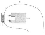
図1に示されるように、本実施形態による内視鏡システムは、ビデオ式硬性鏡装置1と、これを支持する架台2と、滅菌袋3とから、構成されている。
(Constitution)
As shown in FIG. 1, the endoscope system according to the present embodiment includes a video
この架台2は、従来公知のものであり、図示せぬ台座に固定されるクランプ2aと、このクランプ2aに接続された多関節のフリーアーム2bとから、構成されている。
This
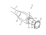
一方、ビデオ式硬性鏡装置1は、患者の腹壁に嵌め込まれたトラカールを介して患者の体腔内に挿入される硬性鏡10と、この硬性鏡10の基端(図示せぬ接眼部13)に接続された撮像装置14とから、構成されている。
On the other hand, the video
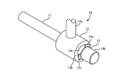
図2は、ビデオ式硬性鏡装置1を構成する硬性鏡10の斜視図であり、図3は、この硬性鏡10の側面図であり、図4は、図3における矢印IV方向からこの硬性鏡1を見たときの背面図である。
2 is a perspective view of the
硬性鏡10は、患者の体腔内に挿入される長尺の円筒形状を有する挿入管11と、この挿入管の基端に同軸に連続する円筒形状を有する円筒部12と、この円筒部12の基端に同軸に連続する円筒形状を有する接眼部13とから、構成されている。
The
挿入管11及び円筒部12内には、その先端から入射した被写体からの光に基づいてその像を形成するための対物レンズと、この像をリレーするための多数のリレーレンズが保持されている。この円筒部12の外径は、挿入管11の外径よりも大きく、その外周面の一カ所から、挿入管11の先端面から照射される照明光を外部の光源装置(図示略)から導入するための可撓性を有するライトガイド12aが、垂直に延びている。
In the
接眼部13内には、最後端のリレーレンズによってリレーされた像を結んだ光をその後端から射出するアイピースレンズが、保持されている。この接眼部13の外径は、円筒部12の外径よりも細く、その後側約3/4(以下、「挿入部13b」という)は、前側約1/4(以下、「マウント部13a」という)よりも更に細い(但し、挿入管11よりは太い)。
In the
このマウント部13aの後端縁には、その径方向に向かって突出する三つのバイヨネット扇部13c,13c,13cが、形成されている。これら三つのバイヨネット扇部13c,13c,13cの形状は、具体的には、マウント部13aの外径よりも大きい半径で頂角がおよそ45°の扇形から、マウント部13aの外径と同じ大きさの半径で頂角が同じ角度の扇形を切り取ったのと等価な形状である。即ち、これらバイヨネット扇部13c,13c,13cが、軸方向及び周方向に不連続な形状の係合部に相当する。そして、三つのバイヨネット扇部13c,13c,13cが、周方向に沿って120°づつの等角度間隔にて配置されているのである。
Three
なお、円筒部12と接眼部13との境の段差は、その中心軸に直交した段差面(以下、「スラスト方向当付部12b」という)を形成している。
The step at the boundary between the
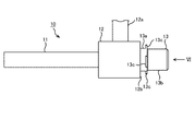
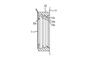
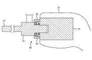
次に、撮像装置14の説明を行う。この撮像装置14は、硬性鏡10によって形成された像を撮像する装置であり、その内部に、図示せぬ結像レンズ及び撮像素子を内蔵している。この撮像装置14の正面図を図5に示し、図5のVI−VI線に沿った縦断面を図6に示す。さらに、硬性鏡10を撮像装置14に装着した状態における縦断面図14に示し、その一部拡大図を図15に示す。但し、各断面図において、その内部構造の図示は省略されている。
Next, the
この撮像装置14は、直方体状の外形を有しており、その先端面には、硬性鏡10の挿入部13bの外径とほぼ同じ内径を有する断面円形の開口である硬性鏡挿入部14aが、形成されている。
The
そして、この先端面における硬性鏡挿入部14aを取り囲むように、その縁から略円筒状に突出した円筒状突出部を硬性するマウント口金22が、取り付けられている。このマウント口金22の形状は、硬性鏡挿入部14aの内径よりも若干大きな内径を有する円筒の内周面に、軸方向の幅が比較的広い断面矩形の円環溝(以下、「内溝部22a」という)を切るとともに、その外周面に、軸方向の幅が比較的狭い断面矩形の円環溝(以下、「外溝部22d」という)を切り、その先端面と内溝部22aとの間に形成された内方フランジ22bに等角度間隔(120度づつの角度間隔)で3つの扇形の切欠き(以下、「バイヨネット雌部22c,22c,22c」という)を形成したのと、ほぼ等価となっている。
A
これら3つのバイヨネット雌部22c,22c,22cは、上記硬性鏡1の三つのバイヨネット扇部13c,13c,13cとほぼ同じ形状に形成されており、これらバイヨネット扇部13cとほぼ同じ大きさか若干大きい大きさを有している。そして、内方フランジ22bにおけるこれら三つのバイヨネット雌部22c,22c,22cによって残された部分が、いわゆるバイヨネット内爪(被係合部)として機能する。
These three bayonet
なお、このマウント口金22の先端面は、硬性鏡挿入部14aの中心軸に直交した方向を向いた円環面(以下、「硬性鏡当付部22e」という)を形成している。この硬性鏡当付部22eから内溝部22aの前端までの距離は、硬性鏡10におけるスラスト方向当付部12bからバイヨネット扇部13cの前端までの距離よりも短く、硬性鏡当付部22eから内溝部22aの後端までの距離は、硬性鏡10におけるスラスト方向当付部12bからバイヨネット扇部13cの後端までの距離よりも長い。
The front end surface of the
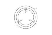
マウント口金22における内溝部22aの内部には、図7の正面図及び図8の斜視図に示すようなリング状のバネリング23が内蔵されている。このバネリング23は、軸方向に視線を向けて見たときの内方フランジ22bと同じような形状に、形成されている。具体的には、輪帯状の金属板の内周縁に、上記バイヨネット雌部22cと同じ形状且つ同じ大きさの三つの切欠き23a,23a,23aが、形成されており、これら切欠き23aが、周方向に沿って120°づつの等角度間隔にて形成されている。
A ring-shaped
また、バネリング23における各切欠き23a,23aに挟まれた部分(上記バヨネット内爪に相当する部分)には、略L字状の切り込み(軸側の縁辺のほぼ中心から径方向に沿った切り込まれるとともに、外周縁に達する前に図7の時計回り方向に沿って切り込まれてできる切り込み)23b,23b,23bが形成されており、これら切り込み23bにて囲まれる片23c,23c,23cが、「く」の字状に折り曲げられることによって、板バネとして構成されている。
In addition, a portion of the
また、バネリング23における各切欠き23a,23aに挟まれた部分における片23c,23c,23cの無い領域には、円形の孔23d,23d,23dが形成されている。そして、マウント口金22の内溝部22aにおける内方フランジ22b側の壁面(軸に直交する面)には、バネリング23の各孔23d,23d,23dに夫々係合する3個の突起が形成されている。各孔23d,23d,23dが夫々突起に係合した状態では、各片23c,23c,23cの先端が内溝部22aにおける後端側の壁面に接して、バネリング23が内方フランジ22bに押し当てられることにより、バネリング23の位置決めがなされる。このようにして位置決めがなされると、バネリング23の各切欠き23aが、被嵌合部22の各バイヨネット雌部22cと重なる。
In addition,
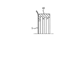
滅菌袋3は、図1に示したような筒状の透明材料(ビニール等)からなる袋であり、その基端(図1における下端)が開放しているとともに、その先端(図1における左上端)が閉じている。この滅菌袋における先端の中央には、略パイプ形状を有する滅菌袋アダプタ4が貫通しており、両者の間が溶着等の手段によって強固に液密且つ気密に接着されている。
The
この滅菌袋アダプタ4は、シリコンゴム等の弾性部材から製造されており、図9及び図10に示す縦断面形状を有している。これら各図に示すように、滅菌袋アダプタ4の内面形状は、マウント口金22の外面形状(即ち、外溝部22dの存在に因って軸方向に不連続な形状)に対応して、このマウント口金22に外側から嵌り合う形状となっている。即ち、この滅菌袋アダプタ4の内面における最大径部の内径は、マウント口金22の外径よりも若干小径となっている。そして、その後端近傍には、マウント口金22の外溝部22dに嵌合する幅及び高さを有する円環状の第1凸部4aが突出形成されている。さらに、マウント口金22における外溝部22dから硬性鏡当付面12bまでの距離に相当する幅の穴部4bを第1凸部4aとの間に開けて、第1凸部4aとほぼ同じ内径(且つ硬性鏡10の円筒部12の外径よりも若干大径)の内方フランジ形状の第2凸部4cが、突出形成されている。なお、この滅菌袋アダプタ4の先端面(第2凸部4cの先端面)は、その中心軸に直交する円環面となっており、出荷時においては、耐候性の高いシートから形成された円形の蓋5が、低強度で液密且つ気密に接合されている。この接合の方法としては、例えば、超音波融着等の手段を用いることができる。
The sterilization bag adapter 4 is manufactured from an elastic member such as silicon rubber and has a vertical cross-sectional shape shown in FIGS. 9 and 10. As shown in these drawings, the inner surface shape of the sterilization bag adapter 4 corresponds to the outer surface shape of the mount base 22 (that is, the shape discontinuous in the axial direction due to the presence of the
(組付手順)
以下、上述した構成を有する各構成部を組み付けて、本実施形態による内視鏡システムをセットアップするための手順について、説明する。なお、説明の前提として、硬性鏡10はオートクレーブによる滅菌処理がなされた状態で、事前に、手術室に運び込まれているものとする。
(Assembly procedure)
Hereinafter, a procedure for setting up the endoscope system according to the present embodiment by assembling the components having the above-described configuration will be described. As a premise for explanation, it is assumed that the
作業者は、手術準備室等、手術室外において、撮像装置14を架台2に取り付ける。そして、一旦手を消毒してから、滅菌袋3を、その外面が撮像装置14及び架台2に接触しないように気をつけながら、その基端から撮像装置14及び架台2に被せてゆき、その基端を基台の下端に縛り付ける。また、作業者は、滅菌袋アダプタ4を、その弾性に抗して押し広げつつ、その基端から撮像装置14のマウント口金22に被せて、その第1凸部4aをマウント口金22の外溝部11dに嵌め込む。但し、この段階では、未だ蓋5を閉じたままであるので、滅菌袋3内に封じ込められた汚染物質が袋外に噴出することがない。
An operator attaches the
以上の作業を行った後に、作業者は、手術着に着替えて、滅菌袋3を被せた撮像装置14及び架台2を手術室に運び込む。手術室内では、作業者は、図10に示すように、滅菌袋アダプタ4から蓋5を除去する。これにより、撮像装置14が手術室内の雰囲気に晒されることになるが、滅菌袋アダプタ4の第1凸部4aがマウント口金22の外溝部22dに嵌り込むとともに穴部4b及び第2凸部4cがマウント口金22の先端面外縁に覆い被さるというように、マウント口金22の外面と滅菌袋アダプタ4の内面との間が複雑な形状の接合面を介して面接触することによって一種のトラップを形成し、しかも、弾性部材からなる滅菌袋アダプタ4がその復元力によってマウント口金22の外周面に密着しているので、滅菌袋3内部の空間は、外部に対して液密且つ気密に保たれている。従って、仮に撮像装置14や架台2の表面に雑菌等の汚染物質が存在していたとしても、かかる汚染物質は、滅菌袋3及び滅菌袋アダプタ4によって封じ込められているので、袋外に噴出して手術室内を汚染することがない。
After performing the above operations, the operator changes into a surgical gown and carries the
次に作業者は、図11乃至図13に示すように、硬性鏡10を撮像装置14に装着する。なお、図11乃至13では、図示の都合上、撮像装置14側の部材としてはバネリング23のみを示す。
Next, the worker attaches the
作業者は、先ず、図11示すように、硬性鏡10の各バイヨネット扇部13c,13c,13cの向きがマウント口金22の各バイヨネット雌部22c,22c,22cの向きと一致するように硬性鏡10の角度を合わせた状態で、その挿入部13bを撮像装置14の硬性鏡挿入部14a内に挿入する。そして、図12に示すように、各バイヨネット扇部13c,13c,13cが各バイヨネット雌部22c,22c,22cを通過して、硬性鏡10のスラスト方向当付部12bがマウント口金22の硬性鏡当付部22eに当接した後に、作業者は、図13に示すように、硬性鏡10全体を反時計方向に捻る。すると、各バイヨネット扇部13c,13c,13cが、バネリング23の各片23c,23c,23cを弾性変形させつつ、これら各片23c,23c,23cと内溝部22aにおける後端側の内壁との間に入り込む。
First, as shown in FIG. 11, the operator sets the rigid mirror so that the orientation of each
各バイヨネット扇部13c,13c,13cが各バイヨネット雌部22c,22c,22c同士の間のバイヨネット内爪と完全に重なった状態で硬性鏡10から力を抜くと、図14及び図15に示すように、各バネリング23の各片23c,23c,23cの弾発力により、各バイヨネット扇部13c,13c,13cが後方に付勢され、それにより、硬性鏡10のスラスト方向当付部12bがマウント口金22の硬性鏡当付部22eに密着させられ、これにより、硬性鏡10の回転と硬性鏡のマウント口金22からの脱落が防止されるとともに、硬性鏡挿入部14aの内部空間が密閉される。従って、汚染物質がこの硬性鏡挿入部14a内に存在していたとしても、以後、かかる汚染物質が外部に噴出して手術室内を汚染することがない。
When the
なお、図14及び図15に示すように、硬性鏡10の円筒部12の外径は、滅菌袋アダプタ4の第2凸部4cの内径よりも若干細いので、両者の間には隙間が生じ、この隙間から、マウント口金22の硬性鏡当付部22eが一部露出している。しかしながら、硬性鏡10を装着する前に硬性鏡当付部22eを消毒液により消毒すれば、衛生上問題はない。
As shown in FIGS. 14 and 15, the outer diameter of the
(作用効果)
以上に説明したように、本実施形態によれば、撮像装置14に対する滅菌処理が不十分であったとしても、この撮像装置14は滅菌袋3によってほぼ完全に覆われるので、手術中の患者の身体に直接翳されることがない。従って、滅菌袋3外に露出する撮像装置14の面積は極小となるので、撮像装置14に付着した汚染物質が漏れる危険が最小限で済む。にも拘わらず、オートクレーブによる完全な滅菌が可能である硬性鏡10は、そのほぼ全体が滅菌袋3の外部に露出しているので、患部の検査及び手術を支障なく行うことができる。また、手術中において、滅菌袋3を交換することなく、硬性鏡10のみを交換して用いることが可能となる。
(Function and effect)
As described above, according to the present embodiment, even if the sterilization process for the
(変形例)
図16及び図17は、本第1実施形態における滅菌袋アダプタ4の変形例を示し、図16はその縦断面図、図17は図16における矢印XVI方向から見た背面図である。即ち、これら図16及び図17は、滅菌袋アダプタ4の第1凸部4aを、互いに分断されて周方向に当角度間隔で配置された3個の扇形の凸部4a’,4a’,4a’に置き換えた例である。
(Modification)
16 and 17 show a modification of the sterilization bag adapter 4 in the first embodiment, FIG. 16 is a longitudinal sectional view thereof, and FIG. 17 is a rear view as seen from the direction of arrow XVI in FIG. That is, FIG. 16 and FIG. 17 show that the first
図18は、本発明の第2の実施形態による内視鏡システムに用いられるビデオ式硬性鏡装置30及び滅菌袋31の縦断面図であり、図19は、その一部拡大図である。これら図18及び図19に示されたように、本第2実施形態は、マウント口金32及び滅菌袋アダプタ33の形状のみが上述した第1実施形態のものと異なり、それ以外の構成を共通にしている。
FIG. 18 is a longitudinal sectional view of the video rigid endoscope device 30 and the
具体的には、本第2実施形態におけるマウント口金32は、第1実施形態のマウント口金22における外周面の先端近傍部分を段差を付けて細くしたのと、等価な形状を有している。これによってマウント口金32の先端に形成された小径部32fの外径は、硬性鏡10の円筒部12の外径よりも小径となっている。また、この小径部22fの後端の段差面は、内溝部32aの前端よりも前方に位置している。
Specifically, the
一方、本第2実施形態における滅菌袋アダプタ33は、図20にその装着前の断面を示すように、第1実施形態の滅菌袋アダプタ4と同様に、第1凸33a,穴部33b及び凸部33cを、有している。但し、この穴部33bの軸方向における幅は、マウント口金32における小径部32fの後端から外溝部32dの前端までの距離と同じとなっており、第2凸33cの厚さ(滅菌袋アダプタ33の前端から穴部33bまでの距離)は、小径部32fの長さ(マウント口金32の前端[硬性鏡当付部32e]から小径部32dの後端までの距離)よりも若干大きい。従って、この滅菌袋アダプタ33をマウント口金32の外周に装着しただけで硬性鏡10を装着していない状態では、図21に示すように、滅菌袋アダプタ33の前端面は、マウント口金32の前端(硬性鏡当付部32e)よりも前方に若干量だけ突出している。さらに、この第2凸部33cの内径は、マウント口金32における小径部32fの外径よりも僅かだけ大径且つ硬性鏡10の円筒部12の外径よりも小径となっている。
On the other hand, the
図21に示す状態下において硬性鏡10を撮像装置14に装着するために、作業者が第1実施形態の場合と同様にして各バイヨネット扇部13c,13c,13cを各バイヨネット雌部32c,32c,32cを通過させると、硬性鏡10のスラスト方向当付部12bがマウント口金32の硬性鏡当付部32eに当接する前に、硬性鏡10のスラスト方向当付部12bが滅菌袋アダプタ33の前端面に当接する。作業者が、この状態から更に硬性鏡10を撮像装置14に押し込むと、滅菌袋アダプタ33の第2凸33cが弾性変形により潰れることにより、硬性鏡10のスラスト方向当付部12bがマウント口金32の硬性鏡当付部32eに当接する。そこで、作業者は、硬性鏡10を捻って、各各バイヨネット扇部13c,13c,13cを各バイヨネット雌部22c,22c,22c同士の間のバイヨネット内爪に係合させる。
In order to attach the
このように、本第2実施形態によると、滅菌袋31外に露出しているマウント口金32と滅菌袋アダプタ33との接合部は、このマウント口金32の硬性鏡当付部32e全域とともに、硬性鏡10のスラスト方向当付部12bによって覆われ、このスラスト方向当付部12bに対する滅菌袋アダプタ33の前端面の密着により、外部に対して密封されている。
As described above, according to the second embodiment, the joint between the
従って、本第2実施形態によると、上述した第1実施形態と比較して、撮像装置14を完全に外部から隔離することができるので、この撮像装置14に付着した汚染物質の漏れを完全に防止することができる。しかも、滅菌袋アダプタ33の前端面は、弾性変形によってスラスト方向当付部12bに密着しているので、仮に撮像装置14に対する操作や架台2の動きに起因して滅菌袋3内の圧力が高まったとしても、滅菌袋3内に存在する汚染物質が外部に噴出ことはない。
Therefore, according to the second embodiment, as compared with the first embodiment described above, the
本第2実施形態におけるその他の構成及び作用効果は、上述した第1実施形態のものと全く同じであるので、その説明を省略する。 Other configurations and operational effects in the second embodiment are exactly the same as those in the first embodiment described above, and a description thereof will be omitted.
図22は、本発明の第3の実施形態による内視鏡システムに用いられるビデオ式硬性鏡装置40及び滅菌袋41の縦断面図であり、図23は、その一部拡大図である。これら図22及び図23に示されたように、本第3実施形態は、マウント口金32及び滅菌袋アダプタ43の形状のみが上述した第1実施形態のものと異なり、それ以外の構成を共通にしている。
FIG. 22 is a longitudinal sectional view of the video
具体的には、本第3実施形態におけるマウント口金32は、上述した第2実施形態のものと全く同じである。一方、本第3実施形態における滅菌袋アダプタ43は、図24にその装着前の断面を示すように、第2実施形態の滅菌袋アダプタ33と比較して、滅菌袋アダプタ43の前端から穴部43bまでの距離がマウント口金32の小径部32fの長さ(マウント口金32の前端[硬性鏡当付部32e]から小径部32dの後端までの距離)と同じである点,穴部43bと第2凸部43cとの間が環状溝状の第2穴部43eとして抉られている点,第2凸部43cの内端に略Oリング形状の密閉部43dが前方へ突出するように一体形成されている点のみが異なり、それ以外の形状が同じである。従って、この滅菌袋アダプタ43をマウント口金32の外周に装着しただけで硬性鏡10を装着していない状態では、滅菌袋アダプタ43の密閉部43dは、マウント口金32の前端(硬性鏡当付部32e)よりも前方に若干量だけ突出する。また、第2凸部43cと小径部22f後端の段差面との間に、空間が形成される。
Specifically, the
この状態下において硬性鏡10を撮像装置14に装着するために、作業者が第1実施形態の場合と同様にして各バイヨネット扇部13c,13c,13cを各バイヨネット雌部32c,32c,32cを通過させると、硬性鏡10のスラスト方向当付部12bがマウント口金32の硬性鏡当付部32eに当接する前に、硬性鏡10のスラスト方向当付部12bが滅菌袋アダプタ43の密閉部43dに当接する。作業者が、この状態から更に硬性鏡10を撮像装置14に押し込むと、滅菌袋アダプタ43の密閉部43dが第2凸部43cの弾性変形により後方に押し出されることにより、硬性鏡10のスラスト方向当付部12bがマウント口金32の硬性鏡当付部32eに当接する。そこで、作業者は、硬性鏡10を捻って、各各バイヨネット扇部13c,13c,13cを各バイヨネット雌部22c,22c,22c同士の間のバイヨネット内爪に係合させる。
In this state, in order to attach the
このように、本第3実施形態によると、滅菌袋41外に露出しているマウント口金32と滅菌袋アダプタ43との接合部は、このマウント口金32の硬性鏡当付部32e全域とともに、硬性鏡10のスラスト方向当付部12bによって覆われ、このスラスト方向当付部12bに対する滅菌袋アダプタ43の密閉部43dの密着により、外部に対して密封されている。
As described above, according to the third embodiment, the joint between the
従って、本第3実施形態によると、上述した第2実施形態と比較しても、滅菌袋アダプタ43の密閉部43dが硬性鏡10のスラスト方向当付部12bに対して線接触するので、接触部における圧力が大きくなるので、より確実に、硬性鏡10のスラスト方向当付部12bと滅菌袋アダプタ43との間を密封することができる。
Therefore, according to the third embodiment, the sealing
本第3実施形態におけるその他の構成及び作用効果は、上述した第1実施形態のものと全く同じであるので、その説明を省略する。 Other configurations and operational effects in the third embodiment are exactly the same as those in the first embodiment described above, and thus the description thereof is omitted.
図25は、本発明の第4の実施形態による内視鏡システムに用いられるビデオ式硬性鏡装置50及び滅菌袋51の縦断面図であり、図26は、その一部拡大図である。これら図25及び図26に示されたように、本第4実施形態は、マウント口金32及び滅菌袋アダプタ53の形状のみが上述した第1実施形態のものと異なり、それ以外の構成を共通にしている。
FIG. 25 is a longitudinal sectional view of a video
具体的には、本第4実施形態におけるマウント口金32は、上述した第2実施形態のものと全く同じである。一方、本第4実施形態における滅菌袋アダプタ43は、図27にその装着前の断面を示すように、第1実施形態の滅菌袋アダプタ4と比較して、滅菌袋アダプタ53の前端から穴部53bまでの距離がマウント口金32の小径部32fの長さ(マウント口金32の前端[硬性鏡当付部32e]から小径部32dの後端までの距離)よりも十分に長い点,穴部53bと第2凸部53cとの間が環状溝状の第2穴部53eとして抉られている点,第2凸部53cの内径が硬性鏡10の円筒部12の外径よりも小径となっている点、第2凸部53cの内端の面形状が縦断面半円形のトロイダル面となっている点のみが異なり、それ以外の形状が同じである。従って、この滅菌袋アダプタ53をマウント口金32の外周に装着しただけで硬性鏡10を装着していない状態では、滅菌袋アダプタ53の第2凸部53cの内径は、硬性鏡10の円筒部12の外径よりも小さい。
Specifically, the
この状態下において硬性鏡10を撮像装置14に装着するためには、作業者は、第1実施形態の場合と同様にして硬性経10の挿入部13bを撮像装置14の硬性鏡挿入部14に挿入すると、各バイヨネット扇部13c,13c,13cが各バイヨネット雌部32c,32c,32cを通過するかしないかのタイミングで、硬性鏡10のスラスト方向当付部12bが滅菌袋アダプタ53の第2凸部53cの内端に当たる。作業者が、この状態から更に硬性鏡10を撮像装置14に押し込むと、スラスト方向当付部12bの縁が第2凸部53cによって形成される孔をその弾性に抗して後方へ押し拡げ、最終的に、硬性鏡10の円筒部12がこの第2凸部53cによって形成される孔を貫通し、硬性鏡10のスラスト方向当付部12bがマウント口金32の硬性鏡当付部32eに当接する。そこで、作業者は、硬性鏡10を捻って、各各バイヨネット扇部13c,13c,13cを各バイヨネット雌部22c,22c,22c同士の間のバイヨネット内爪に係合させる。
In order to attach the
このように、本第4実施形態によると、上述した第1実施形態と比較して、撮像装置14を完全に外部から隔離することができるので、この撮像装置14に付着した汚染物質の漏れを完全に防止することができる。しかも、滅菌袋アダプタ53の第2凸部53cは、弾性変形によって円筒部12にラジアル方向に密着しているので、仮に撮像装置14に対する操作や架台2の動きに起因して滅菌袋51内の圧力が高まったとしても、滅菌袋51内に存在する汚染物質が外部に噴出ことはない。さらに、本第4実施形態によると、上述した第2実施形態及び第3実施形態の場合と異なり、滅菌袋アダプタ53の弾性変形に因る弾発力は、硬性鏡10に対して主としてラジアル方向に作用し、スラスト方向(光軸方向)にはあまり作用しない。従って、第2実施形態及び第3実施形態に比べて、光軸方向における硬性鏡10の位置再現性が向上する。
As described above, according to the fourth embodiment, the
本第4実施形態におけるその他の構成及び作用効果は、上述した第1実施形態のものと全く同じであるので、その説明を省略する。 Other configurations and operational effects in the fourth embodiment are exactly the same as those in the first embodiment described above, and a description thereof will be omitted.
(変形例)
図28乃至図30は、本第4実施形態の滅菌袋アダプタ53における第2凸部53cの先端形状の変形例を示す縦断面図である。即ち、図28は、第2凸部53cの先端の縦断面形状を矩形にした例であり、図29は、第2凸部53cの先端の縦断面形状を各角に夫々Rが付いた矩形にした例であり、図30は、第2凸部53cの先端の縦断面形状をOリング状にした例である。
(Modification)
FIG. 28 thru | or FIG. 30 is a longitudinal cross-sectional view which shows the modification of the front-end | tip shape of the 2nd
図31は、本発明の第5の実施形態による内視鏡システムに用いられるビデオ式硬性鏡装置60及び滅菌袋61の縦断面図であり、図32は、その一部拡大図である。これら図31及び図32に示されたように、本第5実施形態は、マウント口金62及び滅菌袋アダプタ63の形状のみが上述した第1実施形態のものと異なり、それ以外の構成を共通にしている。そして、これらマウント口金62及び滅菌袋アダプタ63は、上述した第2実施形態のマウント口金32及び滅菌袋アダプタ33と比較して、前者の小径部62fと後者の第2凸部63cとを除いた両者の接合面の形状が、図33に示すように多条ねじ形状(両者が相互に半回転するだけで着脱するリードを有した多数のねじ溝/山)である点のみが異なり、それ以外の形状が同じである。
FIG. 31 is a longitudinal sectional view of a video rigid endoscope device 60 and a
本第5実施形態によると、上述した第2実施形態と比較して、マウント口金62及び滅菌袋アダプタ63の接合面が多条ネジ形状であるが故に、その接合面の面積がより大きくなっている。従って、両者間の液密性及び機密性がより向上する。但し、減菌袋3を予め逆方向に捻った状態で装着することが徹底されるならば、上記接合面の形状は一条ネジ形状であっても良い。
According to the fifth embodiment, compared to the second embodiment described above, since the joint surfaces of the
(変形例)
本第5実施形態のような多条ネジ形状を第1実施形態のマウント口金22及び滅菌袋アダプタ4に適用しても良い。その場合、滅菌袋アダプタ4を弾性部材から構成する必要は無くなる。同様に、本第5実施形態のような多条ネジ形状を第2実施形態乃至第4実施形態のマウント口金32及び滅菌袋アダプタ33,43,53に適用しても良い。
(Modification)
The multi-threaded shape as in the fifth embodiment may be applied to the
図34は、本発明の第6の実施形態による内視鏡システムに用いられるビデオ式硬性鏡装置70及び滅菌袋71の縦断面図であり、図35は、ビデオ式硬性鏡装置70’の側面図である。これら図34及び図35に示されたように、本第6実施形態は、第2実施形態と比較して、マウント口金32の内部構造に相当する構成を有さず、マウント口金32の内面に相当する箇所は、平滑な円筒面形状となっている。その代わり、本第6実施形態においては、撮像装置14’に対する硬性鏡10’の固定が、撮像装置14’の硬性鏡挿入部14a’内面に形成された雌ねじと硬性鏡10’の挿入部13b’外面に形成された雄ねじとの螺合(所謂ネジマウント)によってなされている。本第6実施形態におけるその他の構成及び効果は、上述した第2実施形態のものと全く同じであるので、その説明を省略する。
FIG. 34 is a longitudinal sectional view of a video
(変形例)
本第6実施形態において、撮像装置14’に対する硬性鏡10’の固定を、ネジマウントではなくてバイヨネットマウントによって行っても良い。また、本第6実施形態において採用された撮像装置14’に対する硬性鏡10’の固定構造を、第1実施形態,第3実施形態乃至第5実施形態に適用しても良い。
(Modification)
In the sixth embodiment, the
図36は、本発明の第7の実施形態による内視鏡システムに用いられるビデオ式硬性鏡装置80及び滅菌袋85の一部断面側面図である。このビデオ式硬性鏡装置80は、従来一般に用いられている形状を有する硬性鏡81を組み込んだものである。即ち、この内視鏡81は、その接眼部81aが円錐台形状を有しており、上述した第1実施形態における硬性鏡10のようなバイヨネット扇部13cを有していない。また、撮像装置82も従来から用いられているものであり、その内部に図示せぬ結像光学系及び撮像素子を内蔵している。さらに、従来硬性鏡81及び撮像装置82を結合するためのアダプタ83も、その外周面に外溝部83aが形成されている点を除き、従来用いられてたものと同じ構造を有している。
FIG. 36 is a partial cross-sectional side view of the video
即ち、このアダプタ83は、硬性鏡81の図示せぬアイピースレンズから射出された被写体光を撮像装置82に導入するための貫通孔がその中心に穿たれているとともに硬性鏡81の接眼部81aの外径とほぼ同じ内径を有する有底円筒形状の部材と、その内部空間に挿入された接眼部81aのテーパー面を上記有底筒状部材の底面に向けて付勢するバネ部材85とから、硬性されている。そして、その外周面に、縦断面矩形の円環溝(外溝部83a)が形成されている。
That is, the adapter 83 has a through-hole for introducing subject light emitted from an eyepiece lens (not shown) of the
また、滅菌袋83の先端に取り付けられた滅菌袋アダプタ84は、シリコンゴム等の弾性部材から製造されており、図36に示すように、その内面形状は、アダプタ83の外面形状に対応して、このアダプタ83に外側から嵌り合う形状となっている。即ち、この滅菌袋アダプタ84の内面における最大径部の内径は、アダプタ83の外径よりも若干小径となっている。そして、その後端近傍には、アダプタ83の外溝部83aに嵌合する幅及び高さを有する円環状の第1凸部84aが突出形成されている。さらに、アダプタ83における外溝部83aから先端縁までの距離に相当する幅を第1凸部84aとの間に開けて、アダプタ83の内径とほぼ同じ内径の第2凸部84bが突出形成されている。
Moreover, the
本第7実施形態によるその他の構成及び作用効果は、上述した第1実施形態のものと全く同じであるので、その説明を省略する。 Other configurations and operational effects according to the seventh embodiment are exactly the same as those of the first embodiment described above, and thus the description thereof is omitted.
1 ビデオ式硬性鏡装置
3 滅菌袋
4 滅菌袋アダプタ
4a 第1凸部
4b 穴部
4c 第2凸部
10 硬性鏡
12 筒状部
12b スラスト方向当付部
13b 挿入部
13c バイヨネット扇部
14 撮像装置
14a 硬性鏡挿入部
22 マウント口金
22b 内方フランジ
DESCRIPTION OF
Claims (8)
前記硬性鏡の後端近傍の外周面形状は、軸方向及び周方向に不連続な形状の係合部を一部に含む略円柱面形状であり、
前記撮像装置外面には、前記硬性鏡の後端が挿入される開口であるとともに、略円筒状に突出した円筒状突出部がその縁に形成され、また、前記硬性鏡の後端が挿入された状態で回転されることによって前記係合部と係合する被係合部がその内周面に形成された硬性鏡挿入部が形成されており、
前記滅菌袋の先端には、前記円筒状突出部の外周面に嵌る略円筒形状を有する滅菌袋アダプタが、貫通した状態で液密且つ気密に接着されている
ことを特徴とする内視鏡システム。 Built-in objective optical system that forms the image based on the light from the subject incident from the tip, and a rigid mirror that emits the light connecting the image from the base end, and the base end of the rigid mirror In addition, an endoscope system including an imaging device that captures the image and a sterilization bag that covers the imaging device to shield contaminants attached to the imaging device,
The outer peripheral surface shape in the vicinity of the rear end of the rigid endoscope is a substantially cylindrical surface shape including an engagement portion having a discontinuous shape in the axial direction and the circumferential direction.
The outer surface of the imaging device is an opening into which the rear end of the rigid endoscope is inserted, and a cylindrical protruding portion protruding in a substantially cylindrical shape is formed at the edge thereof, and the rear end of the rigid endoscope is inserted. A rigid endoscope insertion portion is formed in which an engaged portion that engages with the engaging portion is formed on the inner peripheral surface thereof by being rotated in a state of being
An endoscope system characterized in that a sterilization bag adapter having a substantially cylindrical shape that fits on an outer peripheral surface of the cylindrical protrusion is bonded to the tip of the sterilization bag in a liquid-tight and air-tight manner in a penetrating state. .
前記滅菌袋アダプタの内周面の形状は、当該円筒状突起部の外周面の形状に係合する形状である
ことを特徴とする請求項1記載の内視鏡システム。 The shape of the outer peripheral surface of the cylindrical protrusion is a discontinuous shape in the axial direction,
The endoscope system according to claim 1, wherein the shape of the inner peripheral surface of the sterilization bag adapter is a shape that engages with the shape of the outer peripheral surface of the cylindrical protrusion.
前記滅菌袋アダプタの内周面には、前記円筒状突起部の外周面に形成された円環状の溝に係合する円環状の突起が形成されていることを特徴とする請求項2記載の内視鏡システム。 An annular groove is formed on the outer peripheral surface of the cylindrical protrusion, and
The annular protrusion that engages with an annular groove formed on the outer peripheral surface of the cylindrical protrusion is formed on the inner peripheral surface of the sterilization bag adapter. Endoscope system.
ことを特徴とする請求項2又は3記載の内視鏡システム。 The endoscope system according to claim 2 or 3, wherein an inner flange that covers the vicinity of the outer edge of the distal end surface of the cylindrical protrusion is formed on the inner peripheral surface of the sterilization bag adapter.
前記円筒状突起部の外周面における先端には、前記フランジ部が嵌る小内径部が形成されているとともに、
前記内方フランジの先端面は、前記係合部が前記被係合部に係合した状態において前記段差面に接触する
ことを特徴とする請求項4記載の内視鏡システム。 The intermediate portion of the rigid endoscope is provided with a cylindrical portion in which a step surface that contacts the distal end surface of the cylindrical protruding portion is formed on the rear end side in a state where the engaging portion is engaged with the engaged portion. And
At the tip of the outer peripheral surface of the cylindrical protrusion, a small inner diameter portion is formed to fit the flange portion,
The endoscope system according to claim 4, wherein the distal end surface of the inner flange is in contact with the stepped surface in a state where the engaging portion is engaged with the engaged portion.
ことを特徴とする請求項5記載の内視鏡システム。 The sterilization bag adapter is made of an elastic member, and the distal end surface of the inner flange projects forward from the distal end surface of the cylindrical protrusion in a state before the rigid mirror is attached, and is inserted into the rigid mirror insertion portion. 6. In a state where the rigid mirror is attached to the imaging device by inserting a rear end thereof, the rigid mirror is deformed in close contact with the step surface of the rigid mirror in a thrust direction. Endoscope system.
前記減菌袋アダプタは弾性部材からなり、前記内方フランジの内端は、前記硬性鏡の取り付け前の状態においては、前記円筒状突起部の先端面よりも前方に突出し、前記硬性鏡挿入部にその後端が挿入されることによって前記硬性鏡が前記撮像装置に取り付けられた状態においては、前記硬性鏡の前記段差面に対してスラスト方向に変形して密着する
ことを特徴とする請求項5記載の内視鏡システム。 A space is formed between the step surface formed at the rear end of the small inner diameter portion and the inner flange,
The sterilization bag adapter is made of an elastic member, and the inner end of the inner flange protrudes forward from the distal end surface of the cylindrical projection in a state before the rigid mirror is attached, 6. In a state where the rigid mirror is attached to the imaging device by inserting a rear end of the rigid mirror, the rigid mirror is deformed in close contact with the step surface of the rigid mirror in a thrust direction. The endoscope system described.
ことを特徴とする請求項4記載の内視鏡システム。 The sterilization bag adapter is made of an elastic member, and the inner end of the inner flange is inserted in the rigid endoscope insertion portion so that the rigid endoscope is attached to the imaging device. The inner surface of the rigid endoscope is deformed and brought into close contact with the outer peripheral surface in a radial direction, and has a smaller inner diameter than the outer diameter of the outer peripheral surface of the rigid endoscope in a state before the rigid endoscope is attached. Item 5. The endoscope system according to Item 4.
Priority Applications (1)
| Application Number | Priority Date | Filing Date | Title |
|---|---|---|---|
| JP2004117108A JP2005296350A (en) | 2004-04-12 | 2004-04-12 | Endoscope system |
Applications Claiming Priority (1)
| Application Number | Priority Date | Filing Date | Title |
|---|---|---|---|
| JP2004117108A JP2005296350A (en) | 2004-04-12 | 2004-04-12 | Endoscope system |
Publications (1)
| Publication Number | Publication Date |
|---|---|
| JP2005296350A true JP2005296350A (en) | 2005-10-27 |
Family
ID=35328610
Family Applications (1)
| Application Number | Title | Priority Date | Filing Date |
|---|---|---|---|
| JP2004117108A Withdrawn JP2005296350A (en) | 2004-04-12 | 2004-04-12 | Endoscope system |
Country Status (1)
| Country | Link |
|---|---|
| JP (1) | JP2005296350A (en) |
Cited By (1)
| Publication number | Priority date | Publication date | Assignee | Title |
|---|---|---|---|---|
| KR20220116387A (en) * | 2021-02-10 | 2022-08-23 | 가부시키가이샤 메이유우 | camera drape |
-
2004
- 2004-04-12 JP JP2004117108A patent/JP2005296350A/en not_active Withdrawn
Cited By (2)
| Publication number | Priority date | Publication date | Assignee | Title |
|---|---|---|---|---|
| KR20220116387A (en) * | 2021-02-10 | 2022-08-23 | 가부시키가이샤 메이유우 | camera drape |
| KR102448681B1 (en) | 2021-02-10 | 2022-09-28 | 가부시키가이샤 메이유우 | camera drape |
Similar Documents
| Publication | Publication Date | Title |
|---|---|---|
| US11986152B2 (en) | Endoscope cap, endoscope and method of manufacturing endoscope cap | |
| JP6640159B2 (en) | Endoscope cap and method of sterilizing endoscope cap | |
| JP3297033B2 (en) | Endoscope | |
| US20170231477A1 (en) | Instrument port with integrated imaging system | |
| JP2019030645A (en) | Cap for endoscope | |
| JP7535727B2 (en) | Rigid endoscope cover and endoscope unit | |
| JPWO2004075740A1 (en) | Tissue excision collection tool | |
| JP6430644B2 (en) | In-vivo imaging device, in-body surveillance camera system | |
| JP2020062436A (en) | Endoscope cap and method for sterilizing endoscopic cap | |
| CN101652093A (en) | Drape for medical equipment, drape for endoscope, and medical device | |
| TWI375549B (en) | Bending instrument for an endoscope and endoscope set | |
| JP5404862B2 (en) | Plug and endoscope | |
| TWI766822B (en) | Camera Protection Bag | |
| JP2005296350A (en) | Endoscope system | |
| JPH07148104A (en) | Endoscope | |
| EP0923350B1 (en) | Sterile surgical coupler and drape | |
| JP3781857B2 (en) | Endoscope | |
| JP3903737B2 (en) | Endoscope insertion part | |
| JPH08182647A (en) | Covered type endoscope | |
| JP4398189B2 (en) | Endoscope | |
| JP3262912B2 (en) | Endoscope with endoscope cover method | |
| KR102818313B1 (en) | A disposable endoscopy tips for rigid endoscope | |
| JPH0661201U (en) | Endoscope cover type endoscope device | |
| JP5289524B2 (en) | Ventilation adapter, endoscope storage device, and endoscope sterilization method | |
| JPH0664606U (en) | Endoscope with endoscope cover method |
Legal Events
| Date | Code | Title | Description |
|---|---|---|---|
| A621 | Written request for application examination |
Free format text: JAPANESE INTERMEDIATE CODE: A621 Effective date: 20070315 |
|
| A711 | Notification of change in applicant |
Free format text: JAPANESE INTERMEDIATE CODE: A712 Effective date: 20080501 |
|
| A977 | Report on retrieval |
Free format text: JAPANESE INTERMEDIATE CODE: A971007 Effective date: 20100217 |
|
| A131 | Notification of reasons for refusal |
Free format text: JAPANESE INTERMEDIATE CODE: A131 Effective date: 20100223 |
|
| A761 | Written withdrawal of application |
Free format text: JAPANESE INTERMEDIATE CODE: A761 Effective date: 20100512 |