JP2005296323A - Guiding tool for reconstructive surgery of anterior cruciate ligaments - Google Patents
Guiding tool for reconstructive surgery of anterior cruciate ligaments Download PDFInfo
- Publication number
- JP2005296323A JP2005296323A JP2004116659A JP2004116659A JP2005296323A JP 2005296323 A JP2005296323 A JP 2005296323A JP 2004116659 A JP2004116659 A JP 2004116659A JP 2004116659 A JP2004116659 A JP 2004116659A JP 2005296323 A JP2005296323 A JP 2005296323A
- Authority
- JP
- Japan
- Prior art keywords
- guide pin
- guide
- femur
- fiber bundle
- bone hole
- Prior art date
- Legal status (The legal status is an assumption and is not a legal conclusion. Google has not performed a legal analysis and makes no representation as to the accuracy of the status listed.)
- Granted
Links
- 210000001264 anterior cruciate ligament Anatomy 0.000 title claims abstract description 30
- 238000002278 reconstructive surgery Methods 0.000 title 1
- 238000003780 insertion Methods 0.000 claims abstract description 49
- 230000037431 insertion Effects 0.000 claims abstract description 49
- 210000000689 upper leg Anatomy 0.000 claims abstract description 32
- 210000003127 knee Anatomy 0.000 claims abstract description 17
- 238000001356 surgical procedure Methods 0.000 claims abstract description 3
- 210000000988 bone and bone Anatomy 0.000 claims description 66
- 239000000835 fiber Substances 0.000 claims description 21
- 238000000034 method Methods 0.000 claims description 15
- 210000003041 ligament Anatomy 0.000 claims 1
- 230000002093 peripheral effect Effects 0.000 abstract 1
- 210000002435 tendon Anatomy 0.000 description 14
- 210000002303 tibia Anatomy 0.000 description 9
- 210000000845 cartilage Anatomy 0.000 description 5
- 230000000694 effects Effects 0.000 description 5
- 210000003205 muscle Anatomy 0.000 description 4
- 238000005553 drilling Methods 0.000 description 3
- 210000002967 posterior cruciate ligament Anatomy 0.000 description 3
- 0 CCC*(C)(C*)C1*(CCCC=**)CCC1 Chemical compound CCC*(C)(C*)C1*(CCCC=**)CCC1 0.000 description 2
- 210000000281 joint capsule Anatomy 0.000 description 2
- 230000000149 penetrating effect Effects 0.000 description 2
- 210000001519 tissue Anatomy 0.000 description 2
- IFTRQJLVEBNKJK-UHFFFAOYSA-N CCC1CCCC1 Chemical compound CCC1CCCC1 IFTRQJLVEBNKJK-UHFFFAOYSA-N 0.000 description 1
- 230000015572 biosynthetic process Effects 0.000 description 1
- 230000037237 body shape Effects 0.000 description 1
- 238000007796 conventional method Methods 0.000 description 1
- 230000006378 damage Effects 0.000 description 1
- 229940079593 drug Drugs 0.000 description 1
- 239000003814 drug Substances 0.000 description 1
- 210000003414 extremity Anatomy 0.000 description 1
- 210000000629 knee joint Anatomy 0.000 description 1
Images


Classifications
-
- A—HUMAN NECESSITIES
- A61—MEDICAL OR VETERINARY SCIENCE; HYGIENE
- A61B—DIAGNOSIS; SURGERY; IDENTIFICATION
- A61B17/00—Surgical instruments, devices or methods
- A61B17/16—Instruments for performing osteoclasis; Drills or chisels for bones; Trepans
- A61B17/17—Guides or aligning means for drills, mills, pins or wires
- A61B17/1714—Guides or aligning means for drills, mills, pins or wires for applying tendons or ligaments
-
- A—HUMAN NECESSITIES
- A61—MEDICAL OR VETERINARY SCIENCE; HYGIENE
- A61B—DIAGNOSIS; SURGERY; IDENTIFICATION
- A61B17/00—Surgical instruments, devices or methods
- A61B17/16—Instruments for performing osteoclasis; Drills or chisels for bones; Trepans
- A61B17/1662—Instruments for performing osteoclasis; Drills or chisels for bones; Trepans for particular parts of the body
- A61B17/1675—Instruments for performing osteoclasis; Drills or chisels for bones; Trepans for particular parts of the body for the knee
-
- A—HUMAN NECESSITIES
- A61—MEDICAL OR VETERINARY SCIENCE; HYGIENE
- A61B—DIAGNOSIS; SURGERY; IDENTIFICATION
- A61B17/00—Surgical instruments, devices or methods
- A61B17/16—Instruments for performing osteoclasis; Drills or chisels for bones; Trepans
- A61B17/17—Guides or aligning means for drills, mills, pins or wires
- A61B17/1739—Guides or aligning means for drills, mills, pins or wires specially adapted for particular parts of the body
- A61B17/1764—Guides or aligning means for drills, mills, pins or wires specially adapted for particular parts of the body for the knee
-
- A—HUMAN NECESSITIES
- A61—MEDICAL OR VETERINARY SCIENCE; HYGIENE
- A61B—DIAGNOSIS; SURGERY; IDENTIFICATION
- A61B17/00—Surgical instruments, devices or methods
- A61B17/56—Surgical instruments or methods for treatment of bones or joints; Devices specially adapted therefor
- A61B17/58—Surgical instruments or methods for treatment of bones or joints; Devices specially adapted therefor for osteosynthesis, e.g. bone plates, screws or setting implements
- A61B17/88—Osteosynthesis instruments; Methods or means for implanting or extracting internal or external fixation devices
- A61B17/8897—Guide wires or guide pins
Landscapes
- Health & Medical Sciences (AREA)
- Surgery (AREA)
- Orthopedic Medicine & Surgery (AREA)
- Life Sciences & Earth Sciences (AREA)
- Engineering & Computer Science (AREA)
- Medical Informatics (AREA)
- Oral & Maxillofacial Surgery (AREA)
- Dentistry (AREA)
- Rheumatology (AREA)
- Biomedical Technology (AREA)
- Heart & Thoracic Surgery (AREA)
- Nuclear Medicine, Radiotherapy & Molecular Imaging (AREA)
- Molecular Biology (AREA)
- Animal Behavior & Ethology (AREA)
- General Health & Medical Sciences (AREA)
- Public Health (AREA)
- Veterinary Medicine (AREA)
- Surgical Instruments (AREA)
Abstract
Description
この発明は膝前十字靭帯を前内側繊維束と後外側繊維束とに分けて再建する術式において後外側繊維束のための大腿骨の骨孔作成時のガイドピンのための誘導具に関するものである。 The present invention relates to a guide for a guide pin when creating a femoral bone hole for a posterior-lateral fiber bundle in a method of reconstruction by dividing the anterior cruciate ligament into an anterior medial fiber bundle and a posterior lateral fiber bundle. It is.
膝前十字靭帯(ACL)は膝関節の内部前面にあり大腿骨と脛骨とを接続することにより膝の屈曲運動の制限を行っている。膝前十字靭帯はスポーツなどの激しい運動によって損傷されやすく断裂に至ることもある。膝前十字靭帯が断裂した場合において行われる膝前十字靭帯再建手術においては、体の適当な部位から代わりになる腱を本人の体の適当な部位から採取し、採取された腱を移植する。従来は患者の体の適当な部位から採取される腱は一本であり、採取された一本の腱を通常の術式に従ってその一端は大腿骨の骨孔に他端は脛骨の骨孔に接合していた(例えば、特許文献1及び特許文献2参照)。 The anterior cruciate ligament (ACL) is located inside the knee joint and restricts the flexion movement of the knee by connecting the femur and tibia. The anterior cruciate ligament is easily damaged by intense exercise such as sports and may lead to tearing. In an anterior cruciate ligament reconstruction operation performed when the anterior cruciate ligament is torn, an alternative tendon is collected from an appropriate part of the body from an appropriate part of the person's body, and the collected tendon is transplanted. Conventionally, there is only one tendon taken from an appropriate part of the patient's body, and one tendon is taken into the femoral bone hole and the other into the tibial bone hole according to the usual procedure. It joined (for example, refer patent document 1 and patent document 2).
従来の術式では一本の腱を移植していたが一本の腱の移植のみでは膝前十字靭帯としての完全な機能を果たしえないことが分かってきた。即ち、膝前十字靭帯は前内側繊維束(AMB)と後外側繊維束(PLB)との二つのバンドからなり、この2本のバンドは膝の角度により相互に機能を分担しており、一本の腱のみを移植するだけでは完全な機能代替を実現し得ない。そこで、膝前十字靭帯の再建に関してもAMBとPLBとで別々に再建するものが提案されている(非特許文献1参照)。
従来におけるAMBとPLBとを分けた膝前十字靭帯の再建においては大腿骨におけるAMBのための骨孔およびPLBのための骨孔はいずれもが屈曲状態に固定された膝の前方より作成されていた。AMBのための骨孔は顆間窩のアイソメトリックポイントに位置しており、前方よりの適正部位への骨孔の作成の作業が容易であった。しかしながら、PLBのための骨孔は膝の伸展位において緊張が強くなるような本来の機能上の必要から大腿骨後顆関節軟骨縁付近が好適であるが、前方からの穿孔は困難であり、AMBのための骨孔と重複して形成されてしまいやすく、大腿骨外顆後方皮質の破壊の可能性もあった。 In the conventional reconstruction of the anterior cruciate ligament which separated AMB and PLB, both the bone hole for AMB and the bone hole for PLB in the femur were created from the front of the knee fixed in the bent state. It was. The bone hole for AMB was located at the isometric point of the intercondylar fossa, and it was easy to create the bone hole at the appropriate site from the front. However, the bone hole for PLB is suitable in the vicinity of the posterior femoral condylar joint cartilage margin because of the original functional necessity that tension becomes strong in the extended position of the knee, but drilling from the front is difficult, It was likely to be formed overlapping with the bone hole for AMB, and there was a possibility of destruction of the femoral epicondyle posterior cortex.
本発明者らは以上述べたいわば前方アプローチによる大腿骨におけるPLBのための骨孔の作成の問題点について鋭意検討したが、膝の内側から大腿骨後顆関節軟骨縁付近をめがけて、いわば、後内側アプローチとも称すべき手法で穿孔することにより好結果を得ることができることがわかった。しかしながら、この場合に目標となる大腿骨後顆関節軟骨縁付近における適正な位置の設定のため医師に相当の熟練を要した。この発明ではこの点に着目し、それほどの熟練を要することなく後内側アプローチにおける大腿骨におけるPLBのための骨孔の作成を可能とすることにある。 The present inventors have intensively studied the problem of creating a bone hole for PLB in the femur by the anterior approach, as described above, but aiming at the vicinity of the posterior condylar joint cartilage margin from the inside of the knee, so to speak, It was found that good results can be obtained by drilling with a technique that should also be called the posterior medial approach. However, considerable skill is required for the doctor in order to set an appropriate position in the vicinity of the femoral posterior condylar joint cartilage margin in this case. The present invention focuses on this point and is intended to enable creation of a bone hole for PLB in the femur in the posterior medial approach without requiring much skill.
請求項1に記載の発明によれば、膝前十字靭帯をAMBとPLBとに分けて再建する術式においてPLBのための大腿骨の骨孔作成時のガイドピンのための誘導具であって、細長本体の端部にAMBのための大腿骨に作成済の骨孔に挿入するための挿入部が形成され、前記挿入部より外側において前記細長本体に、PLBのため大腿骨に骨孔を作成するためのガイドピンを刺入するための外側に開放したガイドピン誘導孔(又は通路)が形成されたことを特徴とする膝前十字靭帯再建手術におけるガイドピン用誘導具が提供される。 According to the first aspect of the present invention, there is provided a guide pin for a guide pin at the time of creating a femoral bone hole for PLB in an operation method in which an anterior cruciate ligament is divided into AMB and PLB for reconstruction. An insertion part for inserting into the bone hole already created in the femur for AMB is formed at the end of the elongated body, and the bone hole is formed in the elongated body outside the insertion part and in the femur for PLB. There is provided a guide pin guide tool in an anterior cruciate ligament reconstruction operation characterized in that a guide pin guide hole (or passage) opened to the outside for inserting a guide pin for making is formed.
請求項2に記載の発明によれば、請求項1に記載の発明において、前記ガイドピン誘導孔はガイドピン挿入部と前記ガイドピン挿入部から前記細長本体の側縁部まで延びるスロット部とから構成されることを特徴とする膝前十字靭帯再建手術におけるガイドピン用誘導具が提供される。 According to a second aspect of the present invention, in the first aspect of the present invention, the guide pin guide hole includes a guide pin insertion portion and a slot portion extending from the guide pin insertion portion to a side edge portion of the elongated body. A guide pin guide for use in reconstruction of the anterior cruciate ligament is provided.
請求項3に記載の発明によれば、請求項1もしくは2に記載の発明において、前記ガイドピン誘導孔は複数設けられていることを特徴とする膝前十字靭帯再建手術におけるガイドピン用誘導具が提供される。 According to a third aspect of the present invention, in the first or second aspect of the present invention, a plurality of guide pin guiding holes are provided, and the guide pin guiding tool in anterior cruciate ligament reconstruction surgery is provided. Is provided.
請求項4に記載の発明によれば、膝前十字靭帯をAMBとPLBとに分けて再建する術式においてPLBのための大腿骨の骨孔作成リーマ誘導具であって、PLBのため大腿骨に刺入されたガイドピン及び必要な補助挿入具が挿入される両端までの貫通孔を形成した外筒本体と、前記外筒本体の一端のハンドル部とからなるリーマ誘導具が提供される。 According to the fourth aspect of the present invention, there is provided a reamer guide tool for creating a femoral bone hole for PLB in an operation method in which the anterior cruciate ligament is divided into AMB and PLB, and the femur for PLB. There is provided a reamer guide comprising an outer cylinder main body having a through hole extending to both ends into which a guide pin and a necessary auxiliary insertion tool inserted are inserted, and a handle portion at one end of the outer cylinder main body.
請求項5に記載の発明によれば、膝前十字靭帯をAMBとPLBとに分けて再建する術式においてPLBのための大腿骨の骨孔作成を行う組合せ道具であって、ガイドピン用誘導具とリーマ用誘導具とから成り、ガイドピン用誘導具は細長本体の端部にAMBのための大腿骨に作成済の骨孔に挿入するための挿入部が形成され、前記挿入部より外側において前記本体に、PLBのため大腿骨に骨孔を作成するためのガイドピンを挿通するための外側に開放したガイドピン誘導孔が形成された、リーマ用誘導具はPLBのため大腿骨に刺入されたガイドピン及び必要な補助挿入具が挿入される両端までの貫通孔を形成した外筒本体と、前記外筒本体の一端のハンドル部とからなることを特徴とする組合せ道具が提供される。 According to the fifth aspect of the present invention, there is provided a combination tool for creating a femoral bone hole for PLB in an operation method in which an anterior cruciate ligament is divided into AMB and PLB and reconstructed. The guide pin guide tool is formed with an insertion portion for inserting a bone hole prepared in the femur for the AMB at the end of the elongated main body, and outside the insertion portion. In the body, a guide pin guide hole opened to the outside for inserting a guide pin for creating a bone hole in the femur for PLB is formed in the main body. There is provided a combination tool comprising an outer cylinder main body having through holes extending to both ends into which inserted guide pins and necessary auxiliary insertion tools are inserted, and a handle portion at one end of the outer cylinder main body. The
請求項1の発明の作用・効果を説明すると、患者の膝は90度屈曲とされ、脛骨の骨孔はAMBとPLBとで共用され、通常の術式に前方より脛骨に移植腱の固定用の骨孔が作成される。即ち、設定された目標点に向けてガイドピン(Kワイヤ)が刺入され、リーマによって所定径まで拡径され、AMBとPLBとで共用の骨孔とされる。他方大腿骨のための骨孔はAMBとPLBとで別個に作成される。AMBのための大腿骨の骨孔の作成位置は顆間窩のアイソメトリックポイントであり、大腿骨の骨孔の作成と同様な通常の術式によって膝の前方よりガイドピン(Kワイヤ)を刺入し、リーマによって所定径とされる。そして、AMBのための骨孔を基準にしてPLBのための大腿骨の骨孔の作成が行われる。即ち、この発明のガイドピン用誘導具を利用してガイドピンの刺入が膝の後内側より行われ、ガイドピンを補助にリーマにより所定径の骨孔とされる。即ち、ガイドピン用誘導具の先端の挿入部はAMBのため既に作成済みの大腿骨の骨孔に前方より挿入される。そして、ガイドピン用誘導具にはPLBのための骨孔作成のガイドピンのための誘導孔が形成されている。ガイドピン誘導具の誘導孔は、ガイドピン誘導具の適正装着状態では、そこに挿入されたガイドピンが大腿骨後顆関節軟骨縁付近を指向するように形成されている。この場合のガイドピン誘導具の誘導孔へのガイドピンの刺入方向は膝の幾分後ろから内向きとなる。ガイドピン誘導具を使用することにより後内側アプローチによる、PLBのための大腿骨の骨孔の作成が比較的経験の少ない医師でも容易確実とすることができる。 The operation and effect of the invention of claim 1 will be explained. The patient's knee is bent 90 degrees, the bone hole of the tibia is shared by AMB and PLB, and is used for fixing the graft tendon to the tibia from the front in the normal operation method. A bone hole is created. That is, a guide pin (K wire) is inserted toward the set target point, and is expanded to a predetermined diameter by a reamer, so that a bone hole is shared by AMB and PLB. On the other hand, the bone hole for the femur is created separately for AMB and PLB. The position of the femoral bone hole for AMB is the isometric point of the intercondylar fossa, and a guide pin (K wire) is inserted from the front of the knee by the same technique as the creation of the femoral bone hole. And it is made a predetermined diameter by the reamer. Then, the femoral bone hole for PLB is created based on the bone hole for AMB. That is, the guide pin is inserted from the back inner side of the knee using the guide pin guide tool of the present invention, and a bone hole having a predetermined diameter is formed by a reamer with the guide pin as an assist. That is, the insertion portion at the distal end of the guide pin guide tool is inserted from the front into the femoral bone hole already created for the AMB. A guide hole for a guide pin for creating a bone hole for PLB is formed in the guide pin guide tool. The guide hole of the guide pin guide is formed so that the guide pin inserted therein is directed near the posterior femoral condylar joint cartilage margin when the guide pin guide is properly attached. In this case, the direction of insertion of the guide pin into the guide hole of the guide pin guide is slightly inward from behind the knee. By using the guide pin guide, creation of a femoral bone hole for PLB by a posterior medial approach can be easily and reliably performed by a relatively inexperienced physician.
請求項2の発明の作用・効果を説明すると、スロット部を設けることによりガイドピン誘導孔にガイドピンを挿入した状態でガイドピン用誘導具を外すことができる。 The operation and effect of the invention of claim 2 will be described. By providing the slot portion, the guide pin guide tool can be removed with the guide pin inserted into the guide pin guide hole.
請求項3の発明の作用・効果を説明すると、複数のガイドピン誘導孔を設けておくことにより患者の体格などによってガイドピン誘導孔を選択することでその患者に最適なPLBのための大腿骨の骨孔位置をより容易に決定することができる。 The operation and effect of the invention of claim 3 will be described. By providing a plurality of guide pin guide holes and selecting the guide pin guide hole according to the patient's physique, etc., the femur for the PLB optimum for the patient The position of the bone hole can be determined more easily.
請求項4の発明の作用・効果を説明すると、ガイドピン用誘導具によって誘電刺入されたガイドピンにリーマ誘導具の本体を挿入し、本リーマ誘導具をハンドル部にて保持した状態でリーマをリーマ誘導具の本体に挿入しリーミングすることで、関節包組織を傷つける恐れなくPLBのための大腿骨の骨孔の作成が可能となる。 The operation and effect of the invention of claim 4 will be described. The reamer guide tool is inserted into the guide pin dielectrically inserted by the guide pin guide tool, and the reamer guide tool is held by the handle portion. Is inserted into the main body of the reamer guide and reamed, thereby making it possible to create a femoral bone hole for PLB without fear of damaging the joint capsule tissue.
請求項5の発明の作用・効果を説明すると、ガイドピン用誘導具とリーマ用誘導具との併用によりPLBのための大腿骨の骨孔の位置設定から実際の骨孔作成までを後内側アプローチにより容易かつ確実に行うことができる。 The operation and effect of the invention of claim 5 will be described. The posterior medial approach from the positioning of the femoral bone hole for PLB to the actual bone hole making by using the guide pin guide tool and the reamer guide tool together. Can be carried out easily and reliably.
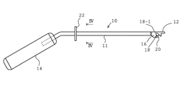
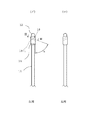
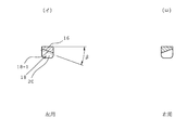
図1はこの発明の膝前十字靭帯(ACL)を前内側繊維束(AMB)と後外側繊維束とに分けて再建する術式においてPLBのための大腿骨の骨孔作成時のガイドピンのための誘導具を示す。ガイドピン誘導具10は細長本体11を備える。細長本体11の一端にAMBのための大腿骨に作成済の骨孔に挿入するための突起部(挿入部)12が形成され、他端に把持用のハンドル14が形成される。突起部12に近接した細長本体11の部分は図1の上下に(ガイドピンの挿入方向に)貫通したガイドピン挿入部16を形成しており、ガイドピン挿入部16にガイドピン挿入孔又は通路18が形成される。ガイドピン挿入孔18はガイドピンの案内部(又はガイドピン案内面)18-1を備え、案内部18-1は所期の挿入方向が得られるように本体軸線に対し水平面で角度α(図2)傾斜しており、直立面で角度β(図3)傾斜している。案内部18-1はガイドピン挿入方向と直交する断面が実質的に半円(図2及び図3では断面で半円形のこの案内部18-1の半径中心を一点鎖線にて示している。)で、この半円の径はガイドピンの径に対応し、案内部18-1に沿ってガイドピンをスムースにガタなく案内(挿入)することができる。案内部のこのガイドピン挿入孔18は図1に示すように斜め下向きに案内部18-1の外径に一致した幅で底面に開口しており、案内部18-1から延びる同一幅開口部分が本発明のスロット20を形成しており、スロット20はガイドピン挿入孔18よりガイドピンを挿入し大腿骨に刺入後にガイドピン誘導具10の抜去を可能とするものである。ガイドピン挿入孔18の位置及び方向(特に角度α及びβ)は、AMBの位置を基準に後述のように決められている。ガイドピン挿入孔18に加えもう一組のガイドピン挿入孔及びスロットを所定距離の部位に設けることができ、体形などによってガイドピン挿入孔の適当な一つを使用するようにし得る。また、ハンドル14の付近において円板状の角度計22(図1及び図4)が設けられ、角度計22上の目盛によりガイドピン誘導具10の角度を即座に把握しながら作業を進めることができるようになっている。ガイドピン誘導具10は左用(図2及び図3の(イ))と右用(図2及び図3の(ロ))とがあり、左用と右用とでガイドピン挿入孔18は対称配置となっている。
FIG. 1 shows a guide pin used when creating a femoral bone hole for PLB in an operation method in which the anterior cruciate ligament (ACL) of the present invention is divided into an anterior medial fiber bundle (AMB) and a posterior lateral fiber bundle. A guiding tool is shown. The
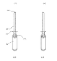
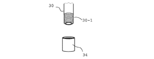
図5にはリーマ誘導具24が示され、リーマ誘導具24は外筒本体26と、外筒本体26の一端のハンドル28とから構成される。外筒本体26には両端まで貫通したのリーマ導入孔29が形成される。そして、外筒本体26の幾分傾斜した前端面26´(図6)は顆間窩壁面に当てられ、この状態でこのリーマ導入孔29にリーマが外端29Aの側から導入され、大腿骨の骨孔の形成が行われる。リーマ誘導具24は左用(図6(イ))と右用(図6(ロ))とで別個に設けられ、左用と右用とで前端面26´の角度は対称となっている。リーマ誘導具24は内筒30と併用して骨孔の形成を行うもので、内筒30の外径はリーマ誘導具24の外筒本体26のリーマ導入孔29(図8)の内径にガタなく挿入される。外筒本体26のため蓋31を設けることができる。他方、内筒30は中心孔32を貫通形成し、この中心孔32にガイドピン(Kワイヤ)がガタなく挿入される寸法となっている。図7に示すように内筒30の外端部はねじ部30-1を形成しており、このねじ部30-1にキャップ34が螺合装着される(図9も参照)。キャップ34は通常時は内筒30に装着されているが、骨孔の作成時は内筒30から離脱される。ハンドル28に近接して角度計36(図5及び図10)が設けられ、角度計36には目盛が刻印されており、目盛の指示を読み取ることによりリーマ誘導具24の角度を即座に把握することができる。
FIG. 5 shows a
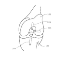
次に、AMBとPLBとを分けた膝前十字靭帯の再建のためのこの発明による骨孔の作成手順について説明するが、この作業は膝関節鏡視下にて行われる。先ず、患者の膝はアルバラード固定器により屈曲90度とし、脛骨に回旋しない肢位に固定される。脛骨の骨孔及び大腿骨のAMBのための骨孔作成に当たっては米国リンバテック社のACLガイドシステムを用いてガイドピンの刺入を行った。目標点としては第1に脛骨付着部の前後中央(具体的には栄養血管、窩間隆起の頂点)、第2の膝後十字靭帯(PCL)の外側縁、第3に顆間窩の最後縁(オーバーザトップ)から3〜6mm前方の3点を結んだ方向とされた。そして、Cリーマを用いて直径10mmの骨孔が作成された。図11には屈曲90度の左側の脛骨100及び大腿骨102を前方より見たところを模式的に示しており、上述のようにして、屈曲した膝前方作成された脛骨100の骨孔を104にて示し、大腿骨102の骨孔を106にて示す。脛骨の骨孔100はAMBとPLBとの双方で共通に使用され、大腿骨の骨孔106はAMBのみに使用される。
Next, a procedure for creating a bone hole according to the present invention for the reconstruction of the anterior cruciate ligament divided into AMB and PLB will be described. This operation is performed under the knee arthroscopy. First, the patient's knee is bent at 90 degrees by an Alvarado fixator and fixed in a limb position that does not rotate around the tibia. When creating a bone hole for the tibial bone hole and femur AMB, a guide pin was inserted using an ACL guide system manufactured by Limbatech, USA. The target points are firstly the front and back of the tibial attachment (specifically, the feeding vessels, the apex of the interproximal ridge), the outer edge of the second posterior cruciate ligament (PCL), and the third end of the intercondylar fossa It was set as the direction which connected three points of 3-6 mm ahead from the edge (over the top). And the bone hole of diameter 10mm was created using C reamer. FIG. 11 schematically shows the
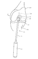
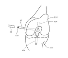
次に、PLBのための大腿骨の骨孔の作成手順について説明すると、ガイドピン誘導具10が膝前方に位置され、突起部12が脛骨100に先のように作成されたAMBのための骨孔104に挿入される。図12は挿入した状態を示す。このとき、角度計22を利用してガイドピン誘導具10の位置を正しく調整する。次に、ガイドピン挿入部16のガイドピン挿入孔18に後内側(矢印a方向)からガイドピン(径2.4mm)の刺入が行われる。ガイドピンの挿入はガイドピン挿入孔18のガイド面18-1に添付けるように行われ、ガイド面18-1(半円形断面)の曲率半径をガイドピンの径に応じて適宜設定することでガタのない円滑な案内を行うことができる。ガイドピンの刺入方向は大腿骨外顆関節軟骨縁から5〜6mm前方で、AMB骨孔104の下縁に接する位置(PCLを基準とした角度では80〜90度)であり、この位置関係が得られるようにガイドピン挿入孔18が決められている。このような後内側からのガイドピンの刺入は関節包組織の保護のため極度に慎重を要し、しかも熟練を要する作業であるが、この発明ではガイドピン誘導具10にガイドピン挿入孔18が上述所定方向に穿設されているため、ガイドピン誘導具10さえ正しく位置していれば、ガイドピン挿入孔18(特にガイド面18-1(角度α及びβ))の助けによりそれほどの熟練を要することなく正確な作業が可能となる。図13にはこのようにして大腿骨の顆間窩の側壁面に後内側方向より刺入されたガイドピン108が示される。ガイドピン108の刺入後にガイドピン108の刺入状態を維持したまま、ガイドピン誘導具10の除去が行われるが、ガイド面18-1に連なり底面まで開口したスロット部20によって干渉を受けることなく作業を行うことができる。
Next, a procedure for creating a femoral bone hole for PLB will be described. A bone for an AMB in which the
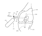
次に、内筒30が端部にキャップ34を螺合した状態でガイドピン108に挿入される。そして、図14のように内筒30の端部のキャップ34が外され、内筒30にリーマ誘導具24がその外筒本体26において挿入される。ガイドピン径とリーマ径とに食い違いがあるが、中間の径の内筒30を使用することによりリーマ誘導具24を大腿骨の骨孔の被作成部に正しく位置させることができる。そして、リーマ誘導具24の外筒本体26をその傾斜前端面26´(図6参照)を大腿骨顆間窩壁面に係合留置した状態で内筒30及びガイドワイヤ108が引き抜かれる。このときのこのとき、リーマ誘導具24の状態を図15にて示し、リーマ誘導具24は“後内側”位置している。そして、図15に示すように内筒30及びガイドワイヤ108を引き抜いた状態でリーマ誘導具24の外筒本体26のリーマ導入孔29にリーマ110の切削先端が導入され、リーマ110によって大腿骨の顆間窩の側壁面に骨孔が作成され、図16はリーマ110による穿孔作業(オーバーリーミング)が完了した状態を示し、PLBのための大腿骨の骨孔114が形成される。
Next, the
このようにして脛骨及び大腿骨の骨孔の作成完了後に膝前十字靭帯(ACL)の機能再建が行われる。即ち、この発明の実施形態においては、AMBの機能再建のためには半腱様筋腱(ST)が、PLB の機能再建のためには薄筋腱(Gr)が用いられ、AMBとなる半腱様筋腱(ST)は4重折のループを用い、一端は脛骨の骨孔104に他端は大腿骨の骨孔106に挿入され、PLBとなる薄筋腱(Gr)は2若しくは3重折のループが用いられ、一端はAMBと共に脛骨の骨孔104に他端は大腿骨の骨孔114に挿入される。このように、関節内に挿入した2本の繊維束の固定は、先ず、膝屈曲角度=20度でAMBとなる半腱様筋腱(ST)の固定を行い、膝屈曲角度=90度でPLB となる薄筋腱(Gr)の行われる。即ち、こられのST, Grはマニュアルマックスの緊張をかけつつ通常の術式に準じてポストスクリュにて固定する。
In this way, the functional reconstruction of the anterior cruciate ligament (ACL) is performed after the creation of the bone holes of the tibia and femur. That is, in the embodiment of the present invention, the semi-tendon-like muscle tendon (ST) is used for AMB function reconstruction, and the thin tendon (Gr) is used for PLB function reconstruction. The tendon-like muscle tendon (ST) uses a fourfold loop, one end is inserted into the
10…ガイドピン誘導具
11…細長本体
12…突起部(挿入部)
16…ガイドピン挿入部
18…ガイドピン挿入孔
18-1…ガイドピン案内面
20…スロット
22…角度計
24…リーマ誘導具
26…外筒本体
28…ハンドル
29…リーマ導入孔
30…内筒
36…角度計
100…脛骨
102…大腿骨
108…ガイドピン
DESCRIPTION OF
16 ... Guide
18-1 ... guide
Claims (5)
A combination tool for creating a femoral bone hole for a posterior lateral fiber bundle in a method of reconstructing an anterior cruciate ligament by dividing it into an anterior medial fiber bundle and a posterior lateral fiber bundle, The guide pin guide tool is formed with an insertion portion for inserting a bone hole prepared in the femur for the anterior inner fiber bundle at the end of the elongated body. A guide pin guide hole that is open to the outside for inserting a guide pin for creating a bone hole in the femur for the posterior-lateral fiber bundle is formed in the main body on the outside. It comprises a guide pin inserted into the femur for bundling and an outer cylinder main body formed with through holes to both ends into which necessary auxiliary insertion tools are inserted, and a handle portion at one end of the outer cylinder main body. A combination tool.
Priority Applications (2)
| Application Number | Priority Date | Filing Date | Title |
|---|---|---|---|
| JP2004116659A JP4245505B2 (en) | 2004-04-12 | 2004-04-12 | Guide for reconstruction of the anterior cruciate ligament |
| US11/061,598 US20050228399A1 (en) | 2004-04-12 | 2005-02-22 | Guiding device for use in anterior cruciate knee ligament reconstruction |
Applications Claiming Priority (1)
| Application Number | Priority Date | Filing Date | Title |
|---|---|---|---|
| JP2004116659A JP4245505B2 (en) | 2004-04-12 | 2004-04-12 | Guide for reconstruction of the anterior cruciate ligament |
Publications (2)
| Publication Number | Publication Date |
|---|---|
| JP2005296323A true JP2005296323A (en) | 2005-10-27 |
| JP4245505B2 JP4245505B2 (en) | 2009-03-25 |
Family
ID=35061561
Family Applications (1)
| Application Number | Title | Priority Date | Filing Date |
|---|---|---|---|
| JP2004116659A Expired - Fee Related JP4245505B2 (en) | 2004-04-12 | 2004-04-12 | Guide for reconstruction of the anterior cruciate ligament |
Country Status (2)
| Country | Link |
|---|---|
| US (1) | US20050228399A1 (en) |
| JP (1) | JP4245505B2 (en) |
Families Citing this family (31)
| Publication number | Priority date | Publication date | Assignee | Title |
|---|---|---|---|---|
| US7736364B2 (en) * | 2006-02-02 | 2010-06-15 | Biomet Sports Medicine, Llc | Method and apparatus for performing ACL reconstruction |
| US20070270962A1 (en) * | 2006-04-26 | 2007-11-22 | Impliant Ltd. | Tools for spinal prostheses |
| US20090149858A1 (en) * | 2007-12-05 | 2009-06-11 | Biomet Sports Medicine, Inc. | Method And Apparatus For Forming A Bone Tunnel |
| WO2009082497A1 (en) | 2007-12-21 | 2009-07-02 | Smith & Nephew, Inc. | Multiple portal guide |
| US9826992B2 (en) | 2007-12-21 | 2017-11-28 | Smith & Nephew, Inc. | Multiple portal guide |
| US8430883B2 (en) * | 2008-02-21 | 2013-04-30 | Covidien Lp | Femoral guide for ACL repair having reduced profile for left/right knee configurations |
| US8343161B2 (en) * | 2008-02-21 | 2013-01-01 | Covidien Lp | Femoral guide for ACL repair having multiple lumen |
| US8282647B2 (en) * | 2008-02-21 | 2012-10-09 | Tyco Healthcare Group Lp | Femoral guide for ACL repair having adjustable offset |
| US8430884B2 (en) * | 2008-02-21 | 2013-04-30 | Covidien Lp | Femoral guide for ACL repair having selectively deployable femoral surface engagement member |
| US8323292B2 (en) * | 2008-12-15 | 2012-12-04 | Spinecore, Inc. | Adjustable pin drill guide and methods therefor |
| US8911474B2 (en) | 2009-07-16 | 2014-12-16 | Howmedica Osteonics Corp. | Suture anchor implantation instrumentation system |
| US9232954B2 (en) | 2009-08-20 | 2016-01-12 | Howmedica Osteonics Corp. | Flexible ACL instrumentation, kit and method |
| WO2012044633A1 (en) | 2010-09-27 | 2012-04-05 | Smith & Nephew, Inc. | Device and methods for use during arthroscopic surgery |
| US10219812B2 (en) | 2010-11-03 | 2019-03-05 | Smith & Nephew, Inc. | Drill guide |
| US9125707B2 (en) | 2011-01-06 | 2015-09-08 | Smith & Nephew, Inc. | Cannulated guide tools |
| US9795398B2 (en) | 2011-04-13 | 2017-10-24 | Howmedica Osteonics Corp. | Flexible ACL instrumentation, kit and method |
| US9918723B2 (en) * | 2011-09-23 | 2018-03-20 | Depuy Mitek, Llc | Glenoid anchor guide |
| US9445803B2 (en) | 2011-11-23 | 2016-09-20 | Howmedica Osteonics Corp. | Filamentary suture anchor |
| US20140039552A1 (en) | 2012-08-03 | 2014-02-06 | Howmedica Osteonics Corp. | Soft tissue fixation devices and methods |
| US8821509B2 (en) * | 2012-10-27 | 2014-09-02 | Danamed, Inc. | Surgical instrument and method of using same |
| US9078740B2 (en) | 2013-01-21 | 2015-07-14 | Howmedica Osteonics Corp. | Instrumentation and method for positioning and securing a graft |
| US9402620B2 (en) | 2013-03-04 | 2016-08-02 | Howmedica Osteonics Corp. | Knotless filamentary fixation devices, assemblies and systems and methods of assembly and use |
| US9788826B2 (en) | 2013-03-11 | 2017-10-17 | Howmedica Osteonics Corp. | Filamentary fixation device and assembly and method of assembly, manufacture and use |
| US9463013B2 (en) | 2013-03-13 | 2016-10-11 | Stryker Corporation | Adjustable continuous filament structure and method of manufacture and use |
| WO2014176270A1 (en) | 2013-04-22 | 2014-10-30 | Pivot Medical, Inc. | Method and apparatus for attaching tissue to bone |
| US10610211B2 (en) | 2013-12-12 | 2020-04-07 | Howmedica Osteonics Corp. | Filament engagement system and methods of use |
| US9986992B2 (en) | 2014-10-28 | 2018-06-05 | Stryker Corporation | Suture anchor and associated methods of use |
| US10568616B2 (en) | 2014-12-17 | 2020-02-25 | Howmedica Osteonics Corp. | Instruments and methods of soft tissue fixation |
| CN106073839B (en) * | 2016-07-25 | 2018-07-03 | 张晓南 | A kind of gate nail for Cruciate ligament reconstruction is oriented to and impactor |
| KR101997827B1 (en) | 2016-10-06 | 2019-07-08 | 사회복지법인 삼성생명공익재단 | Femoral tunnel guide |
| USD902405S1 (en) | 2018-02-22 | 2020-11-17 | Stryker Corporation | Self-punching bone anchor inserter |
Family Cites Families (6)
| Publication number | Priority date | Publication date | Assignee | Title |
|---|---|---|---|---|
| US5320115A (en) * | 1991-01-16 | 1994-06-14 | Applied Biological Concepts | Method and apparatus for arthroscopic knee surgery |
| US5520693A (en) * | 1992-02-19 | 1996-05-28 | Mcguire; David A. | Femoral guide and methods of precisely forming bone tunnels in cruciate ligament reconstruction of the knee |
| US5624446A (en) * | 1992-09-11 | 1997-04-29 | University Of Washington | System for repair of capsulo-labral separations |
| US6902566B2 (en) * | 1997-01-02 | 2005-06-07 | St. Francis Medical Technologies, Inc. | Spinal implants, insertion instruments, and methods of use |
| US6117139A (en) * | 1998-12-25 | 2000-09-12 | Nagoya Screw Mfg., Co., Ltd. | Ligament graft-securing device |
| US6666866B2 (en) * | 2000-11-07 | 2003-12-23 | Osteotech, Inc. | Spinal intervertebral implant insertion tool |
-
2004
- 2004-04-12 JP JP2004116659A patent/JP4245505B2/en not_active Expired - Fee Related
-
2005
- 2005-02-22 US US11/061,598 patent/US20050228399A1/en not_active Abandoned
Also Published As
| Publication number | Publication date |
|---|---|
| JP4245505B2 (en) | 2009-03-25 |
| US20050228399A1 (en) | 2005-10-13 |
Similar Documents
| Publication | Publication Date | Title |
|---|---|---|
| JP4245505B2 (en) | Guide for reconstruction of the anterior cruciate ligament | |
| US7025770B2 (en) | Femoral guide and methods of precisely forming bone tunnels in cruciate ligament reconstruction of the knee | |
| US6022356A (en) | Cruciate ligament reconstruction template | |
| JP4054291B2 (en) | Ligament reconstruction tool and ligament reconstruction method | |
| US8182488B2 (en) | Apparatus and method for implementing patella resection guide during minimally invasive surgery | |
| EP2292162B1 (en) | Tunnel notcher and guidewire delivery device | |
| US8292894B2 (en) | Device for orienting the tibial tunnel position during an ACL reconstruction | |
| US9089433B2 (en) | Canine elbow repair and instrumentation | |
| JP5964545B2 (en) | Apparatus and method for use in ligament regenerative surgery | |
| CN102448394B (en) | Patient-specific joint arthroplasty devices for ligament repair | |
| US20090216243A1 (en) | Guide for creating femoral tunnel during acl reconstruction | |
| US20080306483A1 (en) | Retrograde cutting instrument | |
| US20150133941A1 (en) | Drill pin for fixation of ligaments using button/loop construct | |
| US20070233151A1 (en) | Universal anterior cruciate ligament repair and reconstruction system | |
| US20130289574A1 (en) | Drilling guide for drilling combihole | |
| US8430883B2 (en) | Femoral guide for ACL repair having reduced profile for left/right knee configurations | |
| US7972341B2 (en) | Device for forming a drill hole in bone | |
| US20100049198A1 (en) | Tibial guide for acl repair having off-axis guide wire arrangement | |
| JP5877508B2 (en) | Ligament reconstruction tool, cone and reamer | |
| KR101890150B1 (en) | Guide for reconstruction of cruciate ligaments | |
| JP2008264155A (en) | Ligament reconstruction instrument | |
| Raviraj et al. | Tibial Blowout"-A Complication of Arthroscopic Anterior Cruciate Ligament Reconstruction | |
| Melby III et al. | Over-the-Top Techniques |
Legal Events
| Date | Code | Title | Description |
|---|---|---|---|
| A621 | Written request for application examination |
Free format text: JAPANESE INTERMEDIATE CODE: A621 Effective date: 20070406 |
|
| A977 | Report on retrieval |
Free format text: JAPANESE INTERMEDIATE CODE: A971007 Effective date: 20080918 |
|
| A131 | Notification of reasons for refusal |
Free format text: JAPANESE INTERMEDIATE CODE: A131 Effective date: 20081002 |
|
| A521 | Written amendment |
Free format text: JAPANESE INTERMEDIATE CODE: A523 Effective date: 20081126 |
|
| TRDD | Decision of grant or rejection written | ||
| A01 | Written decision to grant a patent or to grant a registration (utility model) |
Free format text: JAPANESE INTERMEDIATE CODE: A01 Effective date: 20081219 |
|
| A01 | Written decision to grant a patent or to grant a registration (utility model) |
Free format text: JAPANESE INTERMEDIATE CODE: A01 |
|
| A61 | First payment of annual fees (during grant procedure) |
Free format text: JAPANESE INTERMEDIATE CODE: A61 Effective date: 20090106 |
|
| R150 | Certificate of patent or registration of utility model |
Ref document number: 4245505 Country of ref document: JP Free format text: JAPANESE INTERMEDIATE CODE: R150 Free format text: JAPANESE INTERMEDIATE CODE: R150 |
|
| FPAY | Renewal fee payment (event date is renewal date of database) |
Free format text: PAYMENT UNTIL: 20120116 Year of fee payment: 3 |
|
| FPAY | Renewal fee payment (event date is renewal date of database) |
Free format text: PAYMENT UNTIL: 20180116 Year of fee payment: 9 |
|
| R250 | Receipt of annual fees |
Free format text: JAPANESE INTERMEDIATE CODE: R250 |
|
| R250 | Receipt of annual fees |
Free format text: JAPANESE INTERMEDIATE CODE: R250 |
|
| LAPS | Cancellation because of no payment of annual fees |