JP2005296215A - Front-part unit structure for corner of furniture - Google Patents
Front-part unit structure for corner of furniture Download PDFInfo
- Publication number
- JP2005296215A JP2005296215A JP2004115170A JP2004115170A JP2005296215A JP 2005296215 A JP2005296215 A JP 2005296215A JP 2004115170 A JP2004115170 A JP 2004115170A JP 2004115170 A JP2004115170 A JP 2004115170A JP 2005296215 A JP2005296215 A JP 2005296215A
- Authority
- JP
- Japan
- Prior art keywords
- plate
- members
- furniture
- unit structure
- front unit
- Prior art date
- Legal status (The legal status is an assumption and is not a legal conclusion. Google has not performed a legal analysis and makes no representation as to the accuracy of the status listed.)
- Pending
Links
Images


Landscapes
- Drawers Of Furniture (AREA)
- Combinations Of Kitchen Furniture (AREA)
- Cabinets, Racks, Or The Like Of Rigid Construction (AREA)
Abstract
Description
本発明は、家具のコーナー前部ユニット構造に係り、更に詳しくは、相互に交わる方向に配置された板状部材の連結精度や連結強度を高めることができる家具のコーナー前部ユニット構造に関する。 The present invention relates to a corner front unit structure of furniture, and more particularly to a corner front unit structure of furniture that can increase the connection accuracy and connection strength of plate-like members arranged in directions intersecting each other.
従来より、キッチン等において、平面視で略L字状をなすキャビネット等の家具が広く利用されている(特許文献1,2参照)。このような家具のコーナー部に引き出しを設ける場合、その前板は、キャビネットの形状に沿って平面視で略直交するように二枚の板状部材を連結することにより構成される。ここで、二枚の板状部材を連結する構造として、例えば、図8(A)〜(C)に示されるタイプのものが知られている。 Conventionally, furniture such as a cabinet having a substantially L shape in a plan view has been widely used in kitchens or the like (see Patent Documents 1 and 2). When providing drawers at the corners of such furniture, the front plate is configured by connecting two plate-like members so as to be substantially orthogonal in plan view along the shape of the cabinet. Here, as a structure for connecting two plate-like members, for example, the types shown in FIGS. 8A to 8C are known.
図8(A)において、各板状部材80,80の内側木口面81,81には留め加工がそれぞれ施されている。各内側木口面81,81間には、だぼ82が設けられ、当該だぼ82及び接着剤を介して各板状部材80,80が連結されている。
図8(B)では、同図中左側の板状部材80の内側木口面81と、右側の板状部材80の表面83とが当接しており、これらの当接面間にだぼ82及び接着剤を設けて各板状部材80,80が連結されている。
図8(C)では、同図(B)に対し、各板状部材80,80における連結部分の出隅側に沿って、L字状金具85がねじ止め固定されている。
図8(A)〜(C)の各板状部材80,80の後側には、引き出しを構成する底板86が配置され、当該底板86の端面86Aは、各板状部材80,80の後面に沿うように入隅加工が施されている(図8(D)参照)。
In FIG. 8 (A), the
In FIG. 8B, the
In FIG. 8C, an L-
8A to 8C, a
しかしながら、図8(A)及び(B)の構造では、だぼ82の長さが比較的短くなる他、当接面となる内側木口面81の面積が狭いため、各板状部材80,80の交差角度θを直角とする精度が低くなる。しかも、板状部材80,80の連結強度が不十分となり、引き出しの出し入れを繰り返し行うと、板状部材80,80に位置ずれが生じて前記交差角度θを維持し難くなる。このため、板状部材80,80と底板86の端面86Aとの間に隙間が生じ、当該隙間から埃や虫が侵入し易くなるという不都合を生じる。特に、この種の板状部材は、合板を用いることが通常であるため、隙間に水等が入り込むことで腐食を招来することとなる。
また、接着剤を用いて板状部材80,80を連結するため、当該接着剤を塗布する工程の他、接着剤が硬化するまでの待ち時間が必要となり、生産性が低下するという不都合を招来する。
更に、底板86の端面86Aに入隅加工を施す作業に手間や労力を要するという不都合もある。これは、図8(D)に示されるように、直交する二平面により端面86Aを形成するため、同図中矢印X1,X2の二方向から切断刃をそれぞれ進入させる作業と、切断刃が入隅まで達した後に後退させる作業が必要となることに起因する。
However, in the structure shown in FIGS. 8A and 8B, the length of the
In addition, since the plate-
Furthermore, there is a disadvantage that labor and labor are required for the work of performing the corner processing on the
ここで、図8(C)の構造では、L字状金具85を用いているものの、当該L字状金具85が板状部材80,80のコーナー後面だけに接するため、板状部材80,80の連結強度が十分に得られず、引き出しの経時的な使用に伴う板状部材80,80の位置ずれを回避することが困難となる。
しかも、板状部材80,80の後面にL字状金具85が突出するので、当該後面をクロス等によって清掃する際にL字状金具85が邪魔になる他、板状部材80,80と底板86の端面86Aとの間にL字状金具85の厚み分の隙間(図8(C)参照)が生じるという不都合も招来する。
Here, in the structure of FIG. 8C, although the L-
In addition, since the L-shaped metal fitting 85 protrudes from the rear surface of the plate-
[発明の目的]
本発明は、このような不都合に着目して案出されたものであり、その目的は、各板状部材を精度良く配置することができ、各板状部材の連結強度を高めることができる家具のコーナー前部ユニット構造を提供することにある。
[Object of invention]
The present invention has been devised by paying attention to such inconveniences, and the object thereof is furniture in which each plate-like member can be arranged with high accuracy and the connection strength of each plate-like member can be increased. It is to provide a corner front unit structure.
本発明の他の目的は、前部ユニットの生産性を向上させることができる家具のコーナー前部ユニット構造を提供することにある。 Another object of the present invention is to provide a furniture corner front unit structure capable of improving the productivity of the front unit.
前記目的を達成するため、本発明は、平面視で略L字状に設けられた家具本体と、当該家具本体のコーナーに設けられた収納領域とを備えた家具のコーナー前部ユニット構造であって、
前記前部ユニットは、相互に交わる方向に配置された第1及び第2の板状部材と、これら板状部材の内側端部間に配置される連結部材とを含み、
前記連結部材は、各板状部材の内側木口面に当接する第1及び第2の当接部と、前記板状部材の面に沿って位置して当該板状部材に連結される連結部とを備える、という構成を採っている。
In order to achieve the above object, the present invention is a furniture corner front unit structure including a furniture body provided in a substantially L shape in plan view, and a storage area provided in a corner of the furniture body. And
The front unit includes first and second plate-like members arranged in directions intersecting each other, and a connecting member arranged between inner end portions of these plate-like members,
The connecting member includes first and second abutting portions that abut on the inner end face of each plate-like member, and a connecting portion that is located along the surface of the plate-like member and is connected to the plate-like member. It has a configuration that comprises.
本発明において、前記連結部は、片状若しくは板状に形成されている一方、前記第1及び第2の板状部材は、前記連結部を受容する受容部を含み、当該受容部は、連結部の両面を挟み込む溝状に設けられる、という構成を採ることが好ましい。 In the present invention, the connecting portion is formed in a piece or plate shape, while the first and second plate-like members include a receiving portion that receives the connecting portion, and the receiving portion is connected to the connecting portion. It is preferable to adopt a configuration in which a groove is provided to sandwich both sides of the part.
また、連結部材は、第1及び第2の当接部の外方端部間を相互に連結して略筒状体を形成する補強部を更に含む、という構成を採用することができる。 Moreover, the connection member can further employ a configuration in which the outer end portions of the first and second contact portions are connected to each other to further include a reinforcing portion that forms a substantially cylindrical body.
更に、第1及び第2の当接部は、平面視で略L字状に相互に連設されているとともに、前記補強部は平面視略円弧状に形成される、という構成も好ましくは採用される。 Further, the first and second contact portions are preferably connected to each other in a substantially L shape in plan view, and the reinforcing portion is preferably formed in a substantially arc shape in plan view. Is done.
また、前記前部ユニットは、引き出しとされ、前記第1及び第2の板状部材は、前記引き出しの前板を構成するとよい。 The front unit may be a drawer, and the first and second plate-like members may constitute a front plate of the drawer.
更に、前記第1及び第2の板状部材は、前記収納領域の前方を開閉する扉により構成されることが好ましい。 Furthermore, it is preferable that the first and second plate-like members are constituted by doors that open and close the front of the storage area.
本発明によれば、第1及び第2の板状部材において、内側木口面に当接部が当接し、内側木口面と異なる方向に向けられた板状部材の形成面に連結部が連結されるようになる。換言すれば、当接部及び連結部が相互に異なる方向に配置されるので、これらを板状部材の内側端部側に沿わせるだけで、板状部材の向きを簡単且つ精度良く設定することができる。しかも、当接部及び連結部によって連結部材と板状部材との接触面積を広く確保でき、それらの連結強度を良好に維持することが可能となる。これにより、前部ユニットを引き出しとし、当該引き出しの前板を第1及び第2の板状部材により構成した場合、前板の加工精度を高めて、前板の後面及びこれに対向する底板との間に隙間が生じることを防止でき、当該隙間から水、埃や虫が侵入することを回避することが可能となる。一方、第1及び第2の板状部材により開閉可能な扉を構成した場合、当該扉の後面に当接する棧や天板等との密着性を高めて、扉による閉塞性を安定して保つことができる。更に、ねじ等によって板状部材に連結部を連結できるので、従来のように接着剤を用いた場合に比べて製造時間の短縮化が図られ、生産性を向上することができる。 According to the present invention, in the first and second plate-like members, the abutting portion comes into contact with the inner side face, and the connecting portion is connected to the forming surface of the plate-like member oriented in a different direction from the inner side face. Become so. In other words, since the abutting portion and the connecting portion are arranged in different directions, the orientation of the plate-like member can be set easily and accurately simply by placing them along the inner end side of the plate-like member. Can do. In addition, a wide contact area between the connecting member and the plate-like member can be secured by the contact portion and the connecting portion, and the connection strength thereof can be maintained well. Thus, when the front unit is a drawer and the front plate of the drawer is constituted by the first and second plate-like members, the processing accuracy of the front plate is increased, and the rear surface of the front plate and the bottom plate opposed thereto It is possible to prevent a gap from being generated between them, and to prevent water, dust and insects from entering through the gap. On the other hand, when a door that can be opened and closed is constituted by the first and second plate-like members, the closeness of the door is stably maintained by improving the adhesion with a ridge or top plate that contacts the rear surface of the door. be able to. Furthermore, since the connecting portion can be connected to the plate-like member by a screw or the like, the manufacturing time can be shortened and productivity can be improved as compared with the case where an adhesive is used as in the prior art.
また、板状部材に形成された溝状の受容部によって連結部が挟み込まれるので、当該連結部と板状部材との連結強度をより高めることができるばかりでなく、板状部材の前方及び後方から連結部を見えないようにすることができる。これにより、連結部材が板状部材の面から突出しなくなり、拭き掃除等の手入れを容易に行うことが可能となる。 Further, since the connecting portion is sandwiched between the groove-shaped receiving portions formed in the plate-like member, not only can the connection strength between the connecting portion and the plate-like member be increased, but also the front and rear of the plate-like member. It is possible to prevent the connecting portion from being visible. Thereby, a connection member stops protruding from the surface of a plate-shaped member, and it becomes possible to perform care, such as wiping cleaning, easily.
更に、連結部材が略筒状体を形成するので、連結部材自体の強度を高めて、前部ユニットの加工精度を良好に維持することができる他、第1及び第2の板状部材の内側木口面間を連結部材によって塞ぐことが可能となる。 Furthermore, since the connecting member forms a substantially cylindrical body, the strength of the connecting member itself can be increased and the processing accuracy of the front unit can be maintained well, and the inside of the first and second plate-like members It becomes possible to block between the end surfaces by the connecting member.
また、補強部を平面視略円弧状としたから、前部ユニットを引き出しとした場合、各板状部材に接合される底板の端面の入隅も円弧状とすることができる。これにより、底板の端面を切断加工するときに、一連の軌跡に沿って切断刃を移動させることにより前記端面を形成でき、切断加工の簡略化を通じて引き出しの生産性をより高めることができる。 Further, since the reinforcing portion has a substantially arc shape in plan view, when the front unit is a drawer, the corners of the end faces of the bottom plate joined to the plate-like members can also have an arc shape. Thereby, when cutting the end surface of the bottom plate, the end surface can be formed by moving the cutting blade along a series of trajectories, and the productivity of the drawer can be further improved through simplification of the cutting processing.
以下、本発明の好ましい実施の形態について図面を参照しながら説明する。 Hereinafter, preferred embodiments of the present invention will be described with reference to the drawings.
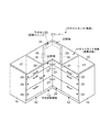
図1には、本実施形態に係るキャビネットの概略斜視図が示されている。この図において、家具としてのキャビネット10は、特に限定されるものでないが、本実施形態では、キッチン用キャビネットとして構成されている。このキャビネット10は、平面視略L字状に設けられた家具本体としてのキャビネット本体11と、このキャビネット本体11の図1中左右両側に設けられた一対のサイド収納領域12,12と、キャビネット本体11のコーナーCに設けられた中央収納領域13とを備えて構成されている。
FIG. 1 is a schematic perspective view of a cabinet according to the present embodiment. In this figure, the cabinet 10 as furniture is not particularly limited, but is configured as a kitchen cabinet in this embodiment. The cabinet 10 includes a cabinet body 11 as a furniture body provided in a substantially L shape in plan view, a pair of
前記家具本体11は、略L字状の平面形状の天板15と、この天板15の図1中左右両側から垂下する一対の外部側板16,16と、各サイド収納領域12,12と中央収納領域13との間に配置された一対の内部側板17,17と、各内部側板17,17の内側に配置されるとともに、同図中上下方向に向けられた一対の中央側板18,18とを備えて構成されている。
The furniture body 11 has a substantially L-shaped
前記各サイド収納領域12,12及び中央収納領域13には、本実施形態では上下三段の引き出し20がそれぞれ配置されている。ここにおいて、中央収納領域13に配置される引き出し20により前部ユニットが構成される。
In each of the
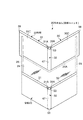
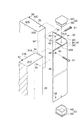
前記中央収納領域13に配置された引き出し20は、図1及び図2に示されるように、天板15のコーナーCにおける前端に沿って平面視略L字状をなす前板22と、この前板22と略平行に配置されて当該前板22と同様に平面視略L字状に形成された背板23と、前板22及び背板23の下部間に配置された底板24と、この底板24の左右両側から起立する一対の側板25,25と、前板22の前面に取り付けられた把手27とを備えて構成されている。図3に示されるように、側板25,25と前記中央側板18,18との間には、スライダ28,28が設けられ、当該スライダ28,28を介して引き出し20を図中二点鎖線で示す方向に引き出せるようになっている。
As shown in FIGS. 1 and 2, the
前記前板22は、図3中左右方向に向けられた第1の板状部材30と、この第1の板状部材30と相互に交わる方向すなわち同図中上下方向に向けられた第2の板状部材31とを含み、各板状部材30,31は、それらの内側端部30A,31A間に配置されて上下方向(図3中紙面直交方向)に延びる連結部材32により相互に連結されている。
The
前記第1及び第2の板状部材30,31は、それらの前面30B,31Bの交差角度θが略90°となるように配置されるとともに、交差角度θに対する二等分線L1を挟んで対称となる構造が採用されている。従って、以下の説明では、第1の板状部材30についてのみ説明し、第1及び第2の板状部材30,31の同一若しくは同等の構成部分については同一符号を用い、説明を省略する。
The first and second plate-
第1の板状部材30は、その内側木口面34に形成された溝状の受容部35を備えている。この受容部35は、図4にも示されるように、第1の板状部材30の板厚方向略中間部において、当該第1の板状部材30の上端から下端に亘って形成されている。また、受容部35は、内側木口面34と略直交する面すなわち第1の板状部材30Bの前面30Bに沿って位置し、後述する連結部を受容するようになっている。第1の板状部材30における前面30Bと内側木口面34とのコーナー部は、平面視で略円弧状に形成されている。図3に示されるように、第1の板状部材30の外側木口面は、テーパ面38とされており、当該テーパ面38に接触するゴム製の緩衝部材39が前記中央側板18の前端面側に取り付けられている。
The first plate-
前記連結部材32は、本実施形態では、アルミニウム製の押し出し形材とされ、前記二等分線L1を挟んで対称形状に形成されている。連結部材32は、第1の板状部材30の内側木口面34に当接する第1の当接部41と、この第1の当接部41に中間部42を介して相互に連設されるとともに、第2の板状部材31の内側木口面34に当接する第2の当接部43と、第1の当接部41に連なるとともに、第1の板状部材30の受容部35に受容される板状の第1の連結部45と、第2の当接部43に連なるとともに、第2の板状部材31の受容部35に受容される板状の第2の連結部46と、第1及び第2の当接部41,43の外方端部41A,43A間を相互に連結する補強部47とを備えて構成されている。
In the present embodiment, the connecting
前記第1及び第2の当接部41,43は、平面視で略直交する方向に向けられて略L字状に形成されている。第1の当接部41は、第2の板状部材31の前面31Bと略同一面上に位置する一方、第2の当接部43は、第1の板状部材30の前面30Bと略同一面上に位置する。
The first and
前記第1の連結部45は、第1の当接部41における内側木口面34との当接面(図3中左面)から略直交する方向に突出し、第2の連結部46は、第2の当接部43における内側木口面34との当接面(図3中下面)から略直交する方向に突出する。従って、第1及び第2の連結部45,46は、相互に略直交する方向に向けられ、第1及び第2の板状部材30,31の前面30B,31Bに沿って位置することとなる。第1及び第2の連結部45,46の前記当接面からの突出高さは、各板状部材30,31の板厚より若干大きく設定されている。第1及び第2の連結部45,46は、その厚さが前記受容部35の溝幅と略同一に設定され、当該受容部35によって両面から挟み込まれる。また、図4に示されるように、各連結部45,46には、上下方向に所定間隔を隔てて複数の穴49が設けられるとともに、それらの穴49に対応する第1及び第2の板状部材30,31の後面30C,31C側にも穴50が設けられ、各穴49,50にねじ51を挿通させることで、第1及び第2の連結部45,46が対応する板状部材30,31に連結されるようになっている。
The first connecting
前記補強部47は、第1及び第2の当接部41,43と中間部42とにより、上下方向に延びる略筒状体Sを形成する。この筒状体Sの上下両側には、キャップ53,53がそれぞれ取り付けられている。各キャップ53,53は、筒状体Sの内周面に圧接する挿入部55と、この挿入部55に連なって筒状体Sの端部に接するとともに、筒状体Sと略同一の平面形状をなす蓋部56とを備え、筒状体Sの上下両端部側を閉塞及び隠蔽するようになっている。
The reinforcing
補強部47は、第1の当接部41の外方端部41Aに連なる第1の後面部58と、第2の当接部43の外方端部43Aに連なる第2の後面部59と、第1及び第2の後面部58,59を連結して後方に向かって膨出するとともに、平面視約1/4円弧状に形成された円弧状部60とを備えている。第1の後面部58は、第1の板状部材30の後面30Cと略同一面上に位置する一方、第2の後面部59は、第2の板状部材31の後面31Cと略同一面上に位置し、これにより、補強部47が各板状部材30,31の後面30C,31Cから、はみ出さないように位置することとなる。
The reinforcing
前記背板23は、前板22に対して左右幅及び上下幅を変更した点を除き、略同一の構造が採用されており、前板22で用いた符号と同一の符号を付し、説明を省略する。
The back plate 23 has substantially the same structure except that the left and right widths and the vertical width are changed with respect to the
前記底板24の前端面24Aは、前板22の後面に沿う平面形状を備え、その入隅が前記円弧状部60に略面接触する円弧状面とされる。
The
以上の構成において、引き出し20を製造するにあたって、底板24の前端面24Aの切断加工は、当該前端面24Aの入隅が円弧状面とされるので、前端面24Aの平面形状に沿う一連の軌跡で切断用の刃を移動させることにより行われる。一方、前板22の組み立ては、第1及び第2の板状部材30,31の内側端部30A,31Aを連結部材32により連結することにより行われる。具体的には、先ず、第1及び第2の連結部45,46を対応する板状部材30,31の受容部35に挿入し、内側木口面34を第1及び第2の当接部41,43に当接させる。このとき、第1及び第2の連結部45,46が受容部35によって挟み込まれるとともに、第1及び第2の板状部材30,31の向き及び位置が決定され、これらの前面30B,31Bの交差角度θが略90°に保たれる。その後、各穴49,50にねじをねじ込むことにより、連結部材32が固定され、当該連結部材32を介して第1及び第2の板状部材30,31が連結されることとなる。そして、背板23も前板22と同様の手順によって組み立てた後、引き出し20を構成する各部材を接合して組み合わせることにより当該引き出し20が完成する。
In the above configuration, when the
従って、このような実施形態によれば、連結部材32の第1及び第2の当接部41,43が内側木口面34に当接し、且つ、第1及び第2の連結部45,46が両面から受容部35に挟み込まれるので、第1及び第2の板状部材30,31と連結部材32との接触面積を広く確保ですることができる。これにより、前板22の形状を安定して保つことができ、引き出し20の出し入れ等の外力により、第1及び第2の板状部材30,31の交差角度θが変化することを防止することが可能となる。
Therefore, according to such an embodiment, the first and second abutting
本発明を実施するための最良の構成、方法などは、以上の記載で開示されているが、本発明は、これに限定されるものではない。
すなわち、本発明は、特定の実施の形態に関して特に図示し、且つ、説明されているが、本発明の技術的思想及び目的の範囲から逸脱することなく、以上に述べた実施例に対し、形状、位置若しくは方向、その他の詳細な構成において、当業者が様々な変形を加えることができるものである。
従って、上記に開示した形状などを限定した記載は、本発明の理解を容易にするために例示的に記載したものであり、本発明を限定するものではないから、それらの形状などの限定の一部若しくは全部の限定を外した部材の名称での記載は、本発明に含まれるものである。
Although the best configuration, method and the like for carrying out the present invention have been disclosed in the above description, the present invention is not limited to this.
That is, the present invention has been particularly shown and described with respect to particular embodiments, but is not limited to the embodiments described above without departing from the scope and spirit of the present invention. Various modifications may be made by those skilled in the art in terms of position, orientation, and other detailed configurations.
Therefore, the description limited to the shape disclosed above is an example for easy understanding of the present invention, and does not limit the present invention. The description by the name of the member which remove | excluded one part or all part is included in this invention.
例えば、前記第1及び第2の板状部材30,31の交差角度θは、90°より大きくしたり小さくしたりすることが可能であり、例えば、図5に示されるように、120°程度に設定してもよい。この際、連結部材32の各当接部41,43及び各連結部45,46の向きは、第1及び第2の板状部材30,31の内側木口面34及び受容部35の向きに対応して変更すればよい。
For example, the crossing angle θ of the first and second plate-
また、第1及び第2の連結部45,46は、図示構成例に限られず、例えば、図6に示されるように、第1及び第2の当接部41,43の外方端部41A,43Aから突出させてもよい。この際、第1及び第2の板状部材30,31の後面30C,31Cに平面視L字形の切欠状の受容部35をそれぞれ形成することにより、後面30C,31Cから第1及び第2の連結部45,46が突出することなく第1及び第2の板状部材30,31に連結できる。
Further, the first and second connecting
更に、図7に示されるように、前記第1及び第2の板状部材30,31と連結部材32とにより、中央収納領域13の前方を開閉する扉62を構成してもよい。この扉62は、第1の板状部材30の外方端部側でヒンジ63を介して中央側板18に連結される。これによれば、中央収納領域13内の底板64や棧(図示省略)において、扉62の後面に当接する端面の入隅加工を前述の底板24の前端面24Aと同様に加工することができる。
Further, as shown in FIG. 7, the first and second plate-
また、前記背板23は、平面視で各側板25,25と略直交するように略フラットな形状としてもよい。
The back plate 23 may have a substantially flat shape so as to be substantially orthogonal to the
更に、前記第1及び第2の連結部45,46は、片状に形成して前記筒状体Sより短くしたり、上下方向に所定間隔を隔てて複数箇所に配置したりしてもよい。
Further, the first and second connecting
また、前記補強部47における第1及び第2の後面部58,59を省略し、第1及び第2の当接部41,43の外方端部41A,43Aを円弧状部60だけで相互に連結する構成としてもよい。
Further, the first and second
更に、本発明は、キッチンに配置されるキャビネット10に限られず、リビングに配置されるコーナー家具等、平面視で略L字状をなす種々の家具に適用することができる。 Furthermore, the present invention is not limited to the cabinet 10 disposed in the kitchen, but can be applied to various furniture having a substantially L shape in plan view, such as corner furniture disposed in a living room.
本発明は、主に、キッチン等の室内空間におけるコーナー部に配置される家具に利用することができる。 INDUSTRIAL APPLICATION This invention can be mainly utilized for the furniture arrange | positioned in the corner part in indoor space, such as a kitchen.
10・・・キャビネット(家具)、11・・・キャビネット本体(家具本体)、13・・・中央収納領域、20・・・引き出し(前部ユニット)、22・・・前板、23・・・背板、30・・・第1の板状部材、30A・・・内側端部、30B・・・前面、31・・・第2の板状部材、31A・・・内側端部、31B・・・前面、32・・・連結部材、34・・・内側木口面、35・・・受容部、41・・・第1の当接部、41A・・・外方端部、43・・・第2の当接部、43A・・・外方端部、45・・・第1の連結部、46・・・第2の連結部、47・・・補強部、62・・・扉、C・・・コーナー、S・・・筒状体 DESCRIPTION OF SYMBOLS 10 ... Cabinet (furniture), 11 ... Cabinet main body (furniture main body), 13 ... Central storage area, 20 ... Drawer (front unit), 22 ... Front plate, 23 ... Back plate, 30 ... first plate member, 30A ... inner end, 30B ... front surface, 31 ... second plate member, 31A ... inner end, 31B ... -Front surface, 32 ... Connecting member, 34 ... Inner side face, 35 ... Receiving portion, 41 ... First contact portion, 41A ... Outer end portion, 43 ... First 2 contact portions, 43A ... outward end portion, 45 ... first connecting portion, 46 ... second connecting portion, 47 ... reinforcing portion, 62 ... door, C. ..Corner, S ... cylindrical body
Claims (6)
前記前部ユニットは、相互に交わる方向に配置された第1及び第2の板状部材と、これら板状部材の内側端部間に配置される連結部材とを含み、
前記連結部材は、各板状部材の内側木口面に当接する第1及び第2の当接部と、前記板状部材の面に沿って位置して当該板状部材に連結される連結部とを備えていることを特徴とする家具のコーナー前部ユニット構造。 A furniture corner front unit structure comprising a furniture body provided in a substantially L shape in plan view and a storage area provided in a corner of the furniture body,
The front unit includes first and second plate-like members arranged in directions intersecting each other, and a connecting member arranged between inner end portions of these plate-like members,
The connecting member includes first and second abutting portions that abut on the inner end face of each plate-like member, and a connecting portion that is located along the surface of the plate-like member and is connected to the plate-like member. A furniture corner front unit structure characterized by comprising:
Priority Applications (1)
| Application Number | Priority Date | Filing Date | Title |
|---|---|---|---|
| JP2004115170A JP2005296215A (en) | 2004-04-09 | 2004-04-09 | Front-part unit structure for corner of furniture |
Applications Claiming Priority (1)
| Application Number | Priority Date | Filing Date | Title |
|---|---|---|---|
| JP2004115170A JP2005296215A (en) | 2004-04-09 | 2004-04-09 | Front-part unit structure for corner of furniture |
Publications (1)
| Publication Number | Publication Date |
|---|---|
| JP2005296215A true JP2005296215A (en) | 2005-10-27 |
Family
ID=35328488
Family Applications (1)
| Application Number | Title | Priority Date | Filing Date |
|---|---|---|---|
| JP2004115170A Pending JP2005296215A (en) | 2004-04-09 | 2004-04-09 | Front-part unit structure for corner of furniture |
Country Status (1)
| Country | Link |
|---|---|
| JP (1) | JP2005296215A (en) |
Cited By (2)
| Publication number | Priority date | Publication date | Assignee | Title |
|---|---|---|---|---|
| JP2011516106A (en) * | 2008-02-29 | 2011-05-26 | ポール ヘティッヒ ゲーエムベーハー ウント ツェーオー. カーゲー | Electrical connection system for furniture drive unit, corner unit, and method for shutting off furniture drive unit |
| CN104473460A (en) * | 2014-11-24 | 2015-04-01 | 青岛帝森露西娜厨具有限公司 | Kitchen all-purpose adjusting unit cabinet |
-
2004
- 2004-04-09 JP JP2004115170A patent/JP2005296215A/en active Pending
Cited By (2)
| Publication number | Priority date | Publication date | Assignee | Title |
|---|---|---|---|---|
| JP2011516106A (en) * | 2008-02-29 | 2011-05-26 | ポール ヘティッヒ ゲーエムベーハー ウント ツェーオー. カーゲー | Electrical connection system for furniture drive unit, corner unit, and method for shutting off furniture drive unit |
| CN104473460A (en) * | 2014-11-24 | 2015-04-01 | 青岛帝森露西娜厨具有限公司 | Kitchen all-purpose adjusting unit cabinet |
Similar Documents
| Publication | Publication Date | Title |
|---|---|---|
| JP2005296215A (en) | Front-part unit structure for corner of furniture | |
| JP4011043B2 (en) | Door and manufacturing method thereof | |
| JP2000050980A5 (en) | ||
| JP2000050980A (en) | Metallic cabinet | |
| KR101308647B1 (en) | Metal frame for furniture | |
| JP2007262658A (en) | Joint structure of strip-like brace and bearing wall panel | |
| JP2008073283A (en) | Metal cabinet | |
| JP4107229B2 (en) | Frame connection structure, frame, leg, joint and furniture | |
| JP5064022B2 (en) | Shelf board | |
| JP3940347B2 (en) | Frame device | |
| JP3923415B2 (en) | Cabinet door | |
| JP5377929B2 (en) | Wall panel of bathroom wall and bathroom unit in bathroom unit | |
| WO2022137587A1 (en) | Joint structure for hollow panels, assembly house, and method for manufacturing hollow panel | |
| JP3599676B2 (en) | Joint fitting | |
| JPH077515Y2 (en) | Structure of joints between decorative boards | |
| JP3705167B2 (en) | Kitchen board storage structure in the bay window corner | |
| JP2018102468A (en) | Fixation structure of shelf board and construction method of shelf board | |
| JP2003241764A (en) | Connector, and connecting structure of panel using the same | |
| JP4370908B2 (en) | Continuous joist floor joist support structure | |
| JPH0678710B2 (en) | Door panel and manufacturing method thereof | |
| JP2002272579A (en) | Folding screen and hinge | |
| JPH11336441A (en) | Door stop shape of toilet booth | |
| JP2010163803A (en) | Door surface of wooden frame door and method for manufacturing the same | |
| JP2003343160A (en) | Doorframe-shaped member | |
| JP2022070370A (en) | Casing used for fixture, fixing structure of casing, and assembly method of fixture |
Legal Events
| Date | Code | Title | Description |
|---|---|---|---|
| A621 | Written request for application examination |
Free format text: JAPANESE INTERMEDIATE CODE: A621 Effective date: 20061005 |
|
| A977 | Report on retrieval |
Free format text: JAPANESE INTERMEDIATE CODE: A971007 Effective date: 20080430 |
|
| A131 | Notification of reasons for refusal |
Free format text: JAPANESE INTERMEDIATE CODE: A131 Effective date: 20091104 |
|
| A02 | Decision of refusal |
Free format text: JAPANESE INTERMEDIATE CODE: A02 Effective date: 20100302 |